2016 FORD SUPER DUTY ECU
[x] Cancel search: ECUPage 211 of 510
WARNINGS
Check attachment of floor mats on
a regular basis. Always properly
reinstall and secure floor mats that
have been removed for cleaning or
replacement. Always make sure that objects
cannot fall into the driver foot well
while the vehicle is moving. Objects
that are loose can become trapped under
the pedals causing a loss of vehicle control. Failure to properly follow floor mat
installation or attachment
instructions can potentially cause
interference with pedal operation causing
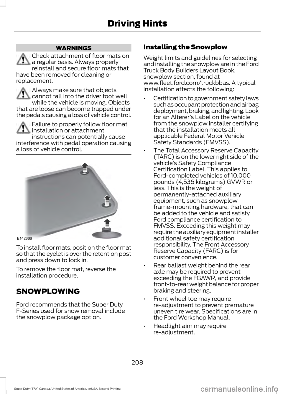
a loss of vehicle control. To install floor mats, position the floor mat
so that the eyelet is over the retention post
and press down to lock in.
To remove the floor mat, reverse the
installation procedure.
SNOWPLOWING
Ford recommends that the Super Duty
F-Series used for snow removal include
the snowplow package option. Installing the Snowplow
Weight limits and guidelines for selecting
and installing the snowplow are in the Ford
Truck Body Builders Layout Book,
snowplow section, found at
www.fleet.ford.com/truckbbas. A typical
installation affects the following:
•
Certification to government safety laws
such as occupant protection and airbag
deployment, braking, and lighting. Look
for an Alterer ’s Label on the vehicle
from the snowplow installer certifying
that the installation meets all
applicable Federal Motor Vehicle
Safety Standards (FMVSS).
• The Total Accessory Reserve Capacity
(TARC) is on the lower right side of the
vehicle ’s Safety Compliance
Certification Label. This applies to
Ford-completed vehicles of 10,000
pounds (4,536 kilograms) GVWR or
less. This is the weight of
permanently-attached auxiliary
equipment, such as snowplow
frame-mounting hardware, that can
be added to the vehicle and satisfy
Ford compliance certification to
FMVSS. Exceeding this weight may
require the auxiliary equipment installer
additional safety certification
responsibility. The Front Accessory
Reserve Capacity (FARC) is for
customer convenience.
• Rear ballast weight behind the rear
axle may be required to prevent
exceeding the FGAWR, and provide
front-to-rear weight balance for proper
braking and steering.
• Front wheel toe may require
re-adjustment to prevent premature
uneven tire wear. Specifications are in
the Ford Workshop Manual.
• Headlight aim may require
re-adjustment.
208
Super Duty (TFA) Canada/United States of America, enUSA, Second Printing Driving HintsE142666
Page 220 of 510
2. If your inquiry or concern remains
unresolved, contact the Sales Manager,
Service Manager or Customer Relations
Manager.
3. If you require assistance or clarification
on Ford Motor Company policies,
please contact the Ford Customer
Relationship Center.
In order to help us serve you better, please
have the following information available
when contacting a Customer Relationship
Center:
• Vehicle Identification Number.
• Your telephone number (home and
business).
• The name of the authorized dealer and
city where located.
• The vehicle ’s current odometer reading.
In some states within the United States,
you must directly notify Ford in writing
before pursuing remedies under your
state's warranty laws, and Ford is also
allowed a final repair attempt.
Additionally, in some states within the
United States, a consumer has the option
of submitting a warranty dispute to the
BBB Auto Line before taking action under
the Magnuson-Moss Warranty Act, or to
the extent allowed by state law, before
pursuing replacement or repurchase
remedies provided by certain state laws.
This dispute handling procedure is not
required prior to enforcing state created
rights or other rights which are independent
of the Magnuson-Moss Warranty Act or
state replacement or repurchase laws. IN CALIFORNIA (U.S. ONLY)
California Civil Code Section 1793.2(d)
requires that, if a manufacturer or its
representative is unable to repair a motor
vehicle to conform to the vehicle
’s
applicable express warranty after a
reasonable number of attempts, the
manufacturer shall be required to either
replace the vehicle with one substantially
identical or repurchase the vehicle and
reimburse the buyer in an amount equal to
the actual price paid or payable by the
consumer (less a reasonable allowance
for consumer use). The consumer has the
right to choose whether to receive a refund
or replacement vehicle.
California Civil Code Section 1793.22(b)
presumes that the manufacturer has had
a reasonable number of attempts to
conform the vehicle to its applicable
express warranties if, within the first 18
months of ownership of a new vehicle or
the first 18000 miles (29 000 km),
whichever occurs first:
1. Two or more repair attempts are made
on the same non-conformity likely to
cause death or serious bodily injury OR
2. Four or more repair attempts are made
on the same nonconformity (a defect
or condition that substantially impairs
the use, value or safety of the vehicle)
OR
3. The vehicle is out of service for repair of nonconformities for a total of more
than 30 calendar days (not necessarily
all at one time).
In the case of 1 or 2 above, the consumer
must also notify the manufacturer of the
need for the repair of the nonconformity
at the following address:
Ford Motor Company
16800 Executive Plaza Drive
Mail Drop 3NE-B
Dearborn, MI 48126
217
Super Duty (TFA) Canada/United States of America, enUSA, Second Printing Customer Assistance
Page 225 of 510
Transport Canada Contact Information
www.tc.gc.ca/eng/motorvehiclesafety/safevehicles-defectinvestigations-
index-76.htm (English)
Website
www.tc.gc.ca/fra/securiteautomobile/VehiculesSecuritaires-Enquetes-
index-76.htm (French)
Website
1–800–333–0510
Phone Ford of Canada Contact Information
www.ford.ca
Website
1–800–565-3673
Phone
222
Super Duty (TFA) Canada/United States of America, enUSA, Second Printing Customer Assistance
Page 258 of 510
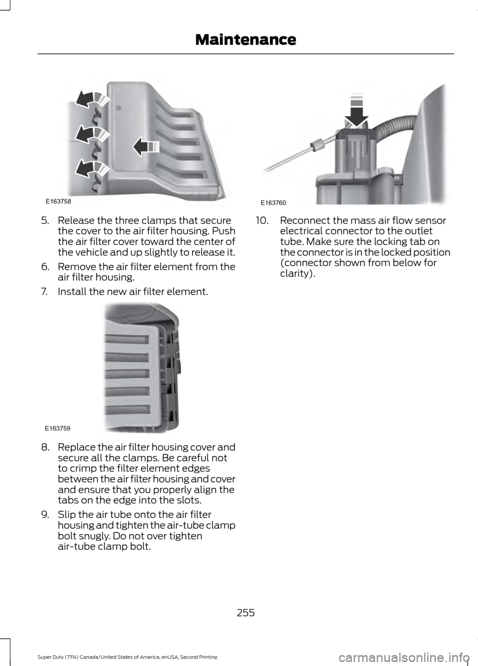
5. Release the three clamps that secure
the cover to the air filter housing. Push
the air filter cover toward the center of
the vehicle and up slightly to release it.
6. Remove the air filter element from the
air filter housing.
7. Install the new air filter element. 8.
Replace the air filter housing cover and
secure all the clamps. Be careful not
to crimp the filter element edges
between the air filter housing and cover
and ensure that you properly align the
tabs on the edge into the slots.
9. Slip the air tube onto the air filter housing and tighten the air-tube clamp
bolt snugly. Do not over tighten
air-tube clamp bolt. 10. Reconnect the mass air flow sensor
electrical connector to the outlet
tube. Make sure the locking tab on
the connector is in the locked position
(connector shown from below for
clarity).
255
Super Duty (TFA) Canada/United States of America, enUSA, Second Printing MaintenanceE163758 E163759 E163760
Page 287 of 510
If your vehicle is equipped with
dual rear wheels it is
recommended that the front and
rear tires (in pairs) be rotated only
side to side. We do not
recommend splitting up the dual
rear wheels. Rotate them side to
side as a set. After tire rotation,
inflation pressures must be
adjusted for the tires new
positions in accordance with
vehicle requirements.
USING SNOW CHAINS
WARNING
Snow tires must be the same size,
load index, speed rating as those
originally provided by Ford. Use of
any tire or wheel not recommended by
Ford can affect the safety and
performance of your vehicle, which could
result in an increased risk of loss of vehicle
control, vehicle rollover, personal injury and
death. Additionally, the use of
non-recommended tires and wheels could
cause steering, suspension, axle, transfer
case or power transfer unit failure. Note:
Do not use snow chains on vehicles
with 20 inch wheels and tires.
The tires on your vehicle have all-weather
treads to provide traction in rain and snow.
However, in some climates, you may need
to use snow tires and cables. If you need
to use cables, it is recommended that steel
wheels (of the same size and
specifications) be used, as cables may chip
aluminum wheels.
Note: The suspension insulation and
bumpers will help prevent vehicle damage.
Do not remove these components from your
vehicle when using snow tires and chains. Follow these guidelines when using snow
tires and chains:
•
If possible, avoid fully loading your
vehicle
• Use only SAE Class S chains.
• Install chains securely, verifying that
the chains do not touch any wiring,
brake lines or fuel lines.
• Drive cautiously. If you hear the chains
rub or bang against your vehicle, stop
and retighten the chains. If this does
not work, remove the chains to prevent
damage to your vehicle.
• Remove the tire chains when they are
no longer needed. Do not use tire
chains on dry roads.
If you have any questions regarding snow
chains or cables, please contact your
authorized dealer.
TIRE PRESSURE MONITORING
SYSTEM WARNING
The tire pressure monitoring system
is not a substitute for manually
checking the tire pressure. The tire
pressure should be checked periodically
(at least monthly) using a tire pressure
gauge. Failure to properly maintain your
tire pressure could increase the risk of tire
failure, loss of control, vehicle rollover and
personal injury. 284
Super Duty (TFA) Canada/United States of America, enUSA, Second Printing Wheels and Tires
Page 299 of 510
7. Stow the jack, jack handle and lug
wrench. Make sure the jack is securely
fastened so it does not rattle when
driving.
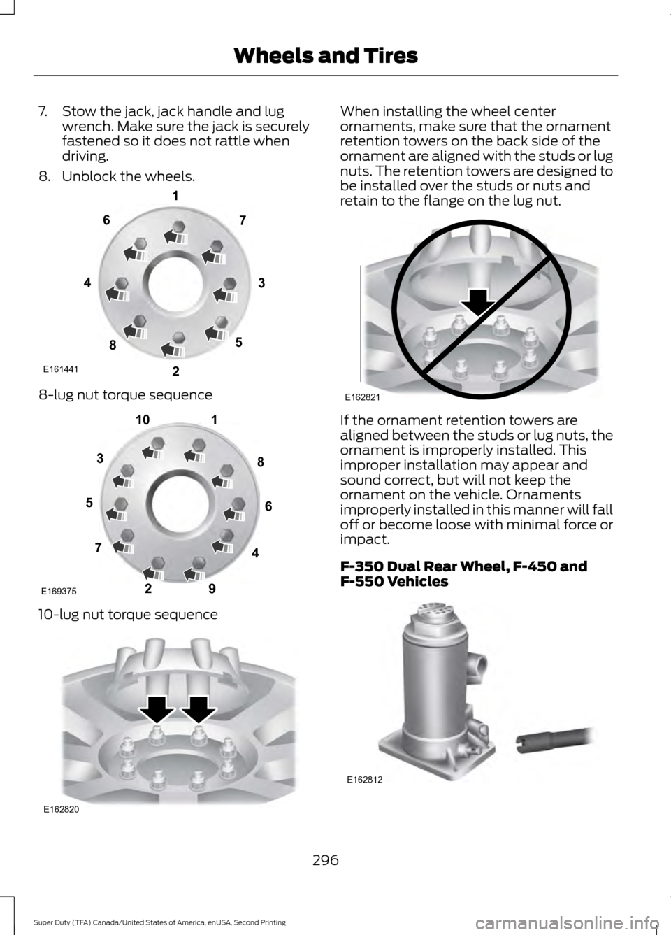
8. Unblock the wheels. 8-lug nut torque sequence
10-lug nut torque sequence When installing the wheel center
ornaments, make sure that the ornament
retention towers on the back side of the
ornament are aligned with the studs or lug
nuts. The retention towers are designed to
be installed over the studs or nuts and
retain to the flange on the lug nut.
If the ornament retention towers are
aligned between the studs or lug nuts, the
ornament is improperly installed. This
improper installation may appear and
sound correct, but will not keep the
ornament on the vehicle. Ornaments
improperly installed in this manner will fall
off or become loose with minimal force or
impact.
F-350 Dual Rear Wheel, F-450 and
F-550 Vehicles
296
Super Duty (TFA) Canada/United States of America, enUSA, Second Printing Wheels and TiresE161441
13
4
27
6
5
8 1
2
3
4
5
6
7 8
9
10
E169375 E162820 E162821 E162812
Page 301 of 510
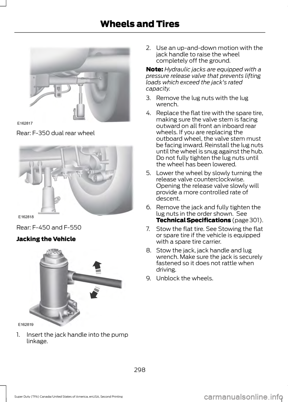
Rear: F-350 dual rear wheel
Rear: F-450 and F-550
Jacking the Vehicle
1. Insert the jack handle into the pump
linkage. 2. Use an up-and-down motion with the
jack handle to raise the wheel
completely off the ground.
Note: Hydraulic jacks are equipped with a
pressure release valve that prevents lifting
loads which exceed the jack's rated
capacity.
3. Remove the lug nuts with the lug wrench.
4. Replace the flat tire with the spare tire,
making sure the valve stem is facing
outward on all front an inboard rear
wheels. If you are replacing the
outboard wheel, the valve stem must
be facing inward. Reinstall the lug nuts
until the wheel is snug against the hub.
Do not fully tighten the lug nuts until
the wheel has been lowered.
5. Lower the wheel by slowly turning the release valve counterclockwise.
Opening the release valve slowly will
provide a more controlled rate of
descent.
6. Remove the jack and fully tighten the lug nuts in the order shown. See
Technical Specifications (page 301).
7. Stow the flat tire. See Stowing the flat or spare tire if the vehicle is equipped
with a spare tire carrier.
8. Stow the jack, jack handle and lug wrench. Make sure the jack is securely
fastened so it does not rattle when
driving.
9. Unblock the wheels.
298
Super Duty (TFA) Canada/United States of America, enUSA, Second Printing Wheels and TiresE162817 E162818 E162819
Page 304 of 510
7.
Repeat this tightness check procedure
when servicing the spare tire pressure
(every six months, per scheduled
maintenance information), or at any
time that the spare tire is disturbed through service of other components.
8. If removed, install the spare tire lock into the bumper drive tube with the
spare tire lock key and jack handle.
TECHNICAL SPECIFICATIONS
Wheel Lug Nut Torque Specifications WARNING
When a wheel is installed, always remove any corrosion, dirt or foreign materials
present on the mounting surfaces of the wheel or the surface of the wheel hub,
brake drum or brake disc that contacts the wheel. Make sure that any fasteners
that attach the rotor to the hub are secured so they do not interfere with the mounting
surfaces of the wheel. Installing wheels without correct metal-to-metal contact at the
wheel mounting surfaces can cause the wheel nuts to loosen and the wheel to come off
while the vehicle is in motion, resulting in loss of control. lb.ft (Nm)
Bolt size
165 lb.ft (224 Nm)
M14 x 1.5
* Torque specifications are for nut and bolt threads free of dirt and rust. Use only Ford
recommended replacement fasteners.
On vehicles equipped with single rear wheels, retighten the lug nuts to the specified torque
at 100 miles (160 kilometers) after any wheel disturbance (such as tire rotation, changing
a flat tire, wheel removal).
On vehicles equipped with dual rear wheels, retighten the wheel lug nuts to the specified
torque at 100 miles (160 kilometers), and again at 500 miles (800 kilometers) of new
vehicle operation and after any wheel disturbance (such as tire rotation, changing a flat
tire, wheel removal).
It is important to follow the proper wheel mounting and lug nut torque procedures.
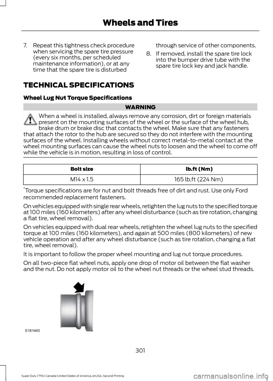
On all two-piece flat wheel nuts, apply one drop of motor oil between the flat washer
and the nut. Do not apply motor oil to the wheel nut threads or the wheel stud threads. 301
Super Duty (TFA) Canada/United States of America, enUSA, Second Printing Wheels and TiresE161443