2016 FORD F450 SUPER DUTY brake
[x] Cancel search: brakePage 180 of 507
PRINCIPLE OF OPERATION
WARNINGS
Hill descent control cannot controldescent in all surface conditions andcircumstances, such as ice orextremely steep grades. Hill descentcontrol is a driver assist system and cannotsubstitute for good judgment by the driver.Failure to do so may result in loss of vehiclecontrol, crash or serious injury.
Hill descent control does not providehill hold at zero miles per hour (0kilometers per hour). When stopped,the parking brake must be applied or thevehicle must be placed in P (Park) or itmay roll away.
Hill descent control allows the driver to setand maintain vehicle speed whiledescending steep grades in various surfaceconditions.
Hill descent control can maintain vehiclespeeds on downhill grades between 2 mph(3 km/h) and 12 mph (20 km/h). Above 20mph (32 km/h), the system remainsarmed, but descent speed cannot be setor maintained.
Hill descent control requires a coolingdown interval after a period of sustaineduse. The amount of time that the featurecan remain active before cooling varieswith conditions. The system will provide awarning in the message center and a chimewill sound when the system is about todisengage for cooling. At this time,manually apply the brakes as needed tomaintain descent speed.
USING HILL DESCENT
CONTROL
Press and release the hilldescent button located on theinstrument panel. A light in thecluster will illuminate and a chime willsound when this feature is activated.
To increase descent speed, press theaccelerator pedal until the desired speedis reached. To decrease descent speed,press the brake pedal until the desiredspeed is reached.
Whether accelerating or decelerating, oncethe desired descent speed is reached,remove your feet from the pedals and thechosen vehicle speed will be maintained.
Note:Noise from the ABS pump motor maybe observed during hill descent controloperation. This is a normal characteristic ofthe ABS and should be no reason forconcern.
Hill descent modes
•At speeds below 20 mph (32 km/h):When the Hill Descent Control switchis pressed and Hill Descent Control isactive, the Hill Descent Control telltalewill flash.
•At speeds below 20 mph (32 km/h):When the Hill Descent Control switchis pressed and conditions are notcorrect for hill descent activation, theHill Descent Control system will beenabled, the Hill Descent Controltelltale will be solid and a message willdisplay in the information display.
•At speeds above 20 mph (32 km/h):When the Hill Descent Control switchis pressed, the Hill Descent Controlsystem will be enabled, the telltale inthe cluster will not be illuminated anda message will be displayed in theinformation display.
177
Super Duty (TFA) Canada/United States of America, enUSA, First Printing
Terrain Response (If Equipped)E163957
Page 186 of 507
PRINCIPLE OF OPERATION
Cruise control lets you maintain a setspeed without keeping your foot on theaccelerator pedal. You can use cruisecontrol when your vehicle speed is greaterthan 20 mph (30 km/h).
USING CRUISE CONTROL
WARNINGS
Do not use cruise control in heavytraffic, on winding roads or when theroad surface is slippery. This couldresult in loss of vehicle control, seriousinjury or death.
When you are going downhill, yourvehicle speed may increase abovethe set speed. The system will notapply the brakes. Change down a gear toassist the system in maintaining the setspeed. Failure to do so could result in lossof vehicle control, serious injury or death.
Note:Cruise control will disengage if thevehicle speed decreases more than 10 mph(16 km/h) below your set speed whiledriving uphill.
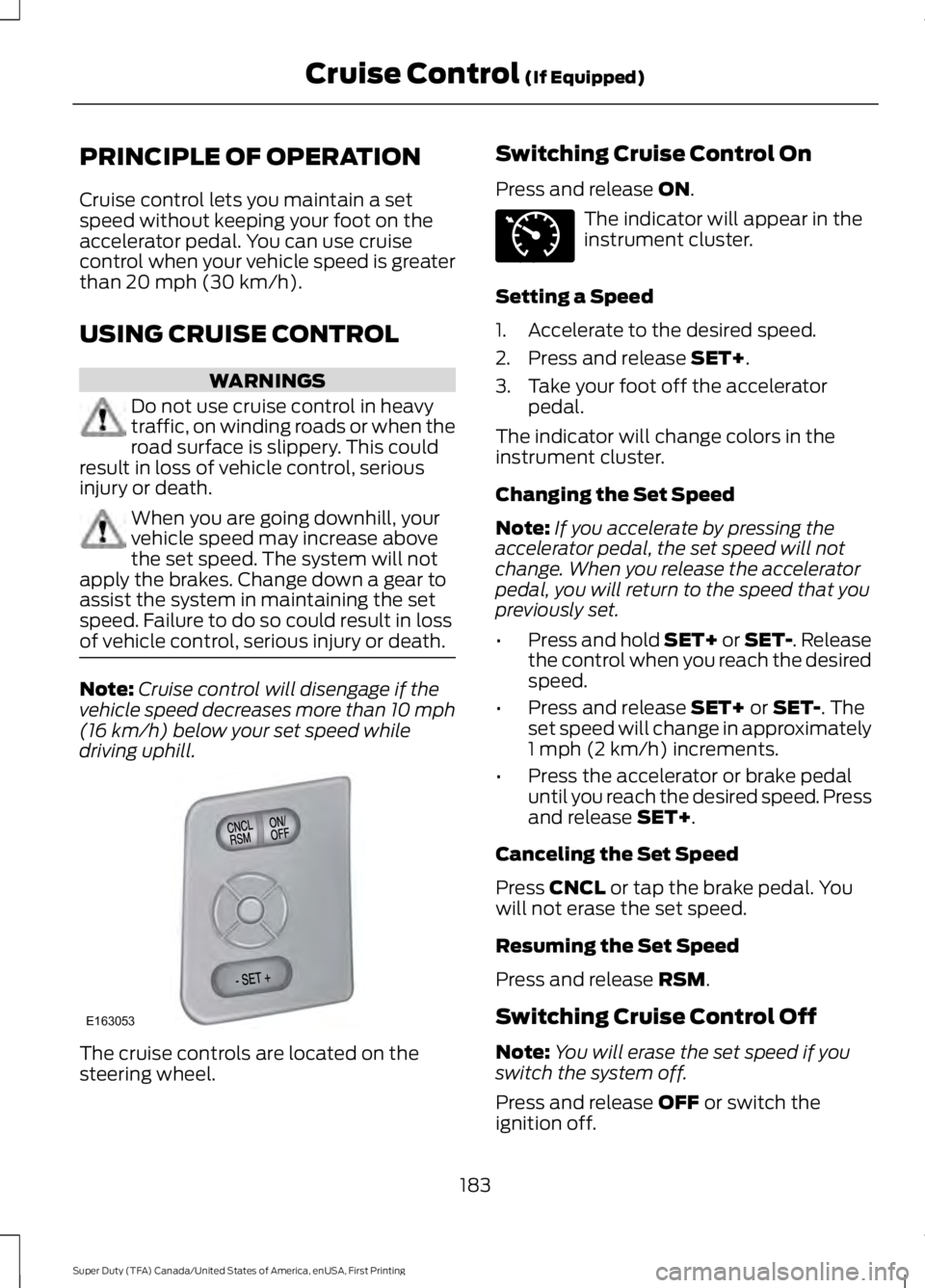
The cruise controls are located on thesteering wheel.
Switching Cruise Control On
Press and release ON.
The indicator will appear in theinstrument cluster.
Setting a Speed
1. Accelerate to the desired speed.
2. Press and release SET+.
3. Take your foot off the acceleratorpedal.
The indicator will change colors in theinstrument cluster.
Changing the Set Speed
Note:If you accelerate by pressing theaccelerator pedal, the set speed will notchange. When you release the acceleratorpedal, you will return to the speed that youpreviously set.
•Press and hold SET+ or SET-. Releasethe control when you reach the desiredspeed.
•Press and release SET+ or SET-. Theset speed will change in approximately1 mph (2 km/h) increments.
•Press the accelerator or brake pedaluntil you reach the desired speed. Pressand release SET+.
Canceling the Set Speed
Press CNCL or tap the brake pedal. Youwill not erase the set speed.
Resuming the Set Speed
Press and release RSM.
Switching Cruise Control Off
Note:You will erase the set speed if youswitch the system off.
Press and release OFF or switch theignition off.
183
Super Duty (TFA) Canada/United States of America, enUSA, First Printing
Cruise Control (If Equipped)E163053 E71340
Page 192 of 507
GCW (Gross Combined Weight)- is the Gross Vehicle Weight plusthe weight of the fully loadedtrailer.
GCWR (Gross CombinedWeight Rating) - is the maximumallowable weight of the vehicleand the loaded trailer, includingall cargo and passengers, that thevehicle can handle without riskingdamage. (Important: The towingvehicle’s braking system is ratedfor operation at Gross VehicleWeight Rating, not at GrossCombined Weight Rating.)Separate functional brakes shouldbe used for safe control of towedvehicles and for trailers where theGross Combined Weight of thetowing vehicle plus the trailerexceed the Gross Vehicle WeightRating of the towing vehicle.TheGross Combined Weight mustnever exceed the GrossCombined Weight Rating.
Maximum Loaded TrailerWeight - is the highest possibleweight of a fully loaded trailer thevehicle can tow. It assumes avehicle with mandatory options,driver and front passenger weight(150 pounds [68 kilograms]each), no cargo weight (internalor external) and a tongue load of10–15% (conventional trailer) orking pin weight of 15–25% (fifthwheel trailer). Consult anauthorized dealer (or the RV andTrailer Towing Guide available at
an authorized dealer) for moredetailed information.
Tongue Load or Fifth WheelKing Pin Weight - refers to theamount of the weight that a trailerpushes down on a trailer hitch.
Examples: For a 5000 pound(2268 kilogram) conventionaltrailer, multiply 5000 by 0.10 and0.15 to obtain a proper tongueload range of 500 to 750 pounds(227 to 340 kilograms). For an11500 pound (5216 kilogram) fifthwheel trailer, multiply by 0.15 and0.25 to obtain a proper king pinload range of 1725 to 2875 pounds(782 to 1304 kilograms).
WARNINGS
Do not exceed the GVWR orthe GAWR specified on theSafety Compliance CertificationLabel.
Do not use replacement tireswith lower load carryingcapacities than the original tiresbecause they may lower thevehicle’s GVWR and GAWRlimitations. Replacement tireswith a higher limit than the originaltires do not increase the GVWRand GAWR limitations.
Exceeding any vehicle weightrating limitation could resultin serious damage to the vehicleand/or personal injury.
Steps for determining thecorrect load limit:
189
Super Duty (TFA) Canada/United States of America, enUSA, First Printing
Load Carrying
Page 195 of 507
TOWING A TRAILER
WARNINGS
Do not exceed the GVWR orthe GAWR specified on thecertification label.
Towing trailers beyond themaximum recommendedgross trailer weight exceeds thelimit of the vehicle and couldresult in engine damage,transmission damage, structuraldamage, loss of vehicle control,vehicle rollover and personalinjury.
Your vehicle may have electricalitems, such as fuses or relays,related to towing. See the Fuseschapter.
Your vehicle's load capacitydesignation is by weight, not byvolume, so you cannot necessarilyuse all available space whenloading a vehicle or trailer.
Towing a trailer places an extraload on your vehicle's engine,transmission, axle, brakes, tiresand suspension. Inspect thesecomponents periodically during,and after, any towing operation.
Load Placement
To help minimize how trailermovement affects your vehiclewhen driving:
•Load the heaviest items closestto the trailer floor.
•Load the heaviest itemscentered between the left andright side trailer tires.
•Load the heaviest items abovethe trailer axles or just slightlyforward toward the trailertongue. Do not allow the finaltrailer tongue weight to goabove or below 10-15% of theloaded trailer weight.
•Select a tow bar with thecorrect rise or drop. When boththe loaded vehicle and trailerare connected, the trailer frameshould be level, or slightlyangled down toward yourvehicle, when viewed from theside.
When driving with a trailer orpayload, a slight takeoff vibrationor shudder may be present due tothe increased payload weight.Additional information regardingproper trailer loading and settingyour vehicle up for towing islocated in another chapter of thismanual. See Load Limit (page185).
You can also find information inthe RV & Trailer Towing Guideavailable at your authorizeddealer, or online.
192
Super Duty (TFA) Canada/United States of America, enUSA, First Printing
Towing
Page 196 of 507
RV & Trailer Towing Guide Online
http://www.fleet.ford.com/towing-guides/Website
TRAILER SWAY CONTROL (If
Equipped)
WARNING
Turning off trailer sway controlincreases the risk of loss of vehiclecontrol, serious injury or death. Forddoes not recommend disabling this featureexcept in situations where speed reductionmay be detrimental (such as hill climbing),the driver has significant trailer towingexperience, and can control trailer swayand maintain safe operation.
Note:This feature does not prevent trailersway, but reduces it once it begins.
Note:This feature cannot stop all trailersfrom swaying.
Note:In some cases, if vehicle speed is toohigh, the system may activate multipletimes, gradually reducing vehicle speed.
This feature applies your vehicle brakes atindividual wheels and, if necessary, reducesengine power. If the trailer begins to sway,the stability control light flashes and themessage TRAILER SWAY REDUCESPEED appears in the information display.The first thing to do is slow your vehicledown, then pull safely to the side of theroad and check for proper tongue load andtrailer load distribution. See LoadCarrying (page 185).
RECOMMENDED TOWING
WEIGHTS
Note:Make sure to take intoconsideration trailer frontal area.Do not exceed 60 feet2 (5.6
meters2) trailer frontal area for
conventional trailers. Do notexceed 75 feet2 (6.9 meters2) trailer
frontal area for 5th wheel andgooseneck trailers.
Note:Exceeding this limitationmay significantly reduce theperformance of your towingvehicle. Selecting a trailer with alow aerodynamic drag and roundedfront design helps optimizeperformance and fuel economy.
Note:For high altitude operation,reduce the gross combined weightby 2% per 1000 feet (300 meters)starting at the 1000 foot (300meter) elevation point.
Note:Certain states requireelectric trailer brakes for trailersover a specified weight. Be sure tocheck state regulations for thisspecified weight. The maximumtrailer weights listed may be limitedto this specified weight, as yourvehicle's electrical system may notinclude the wiring connector
needed to use electric trailerbrakes.
193
Super Duty (TFA) Canada/United States of America, enUSA, First Printing
Towing
Page 200 of 507
Remember to account for the trailertongue weight as part of your vehicle loadwhen calculating the total vehicle weight.
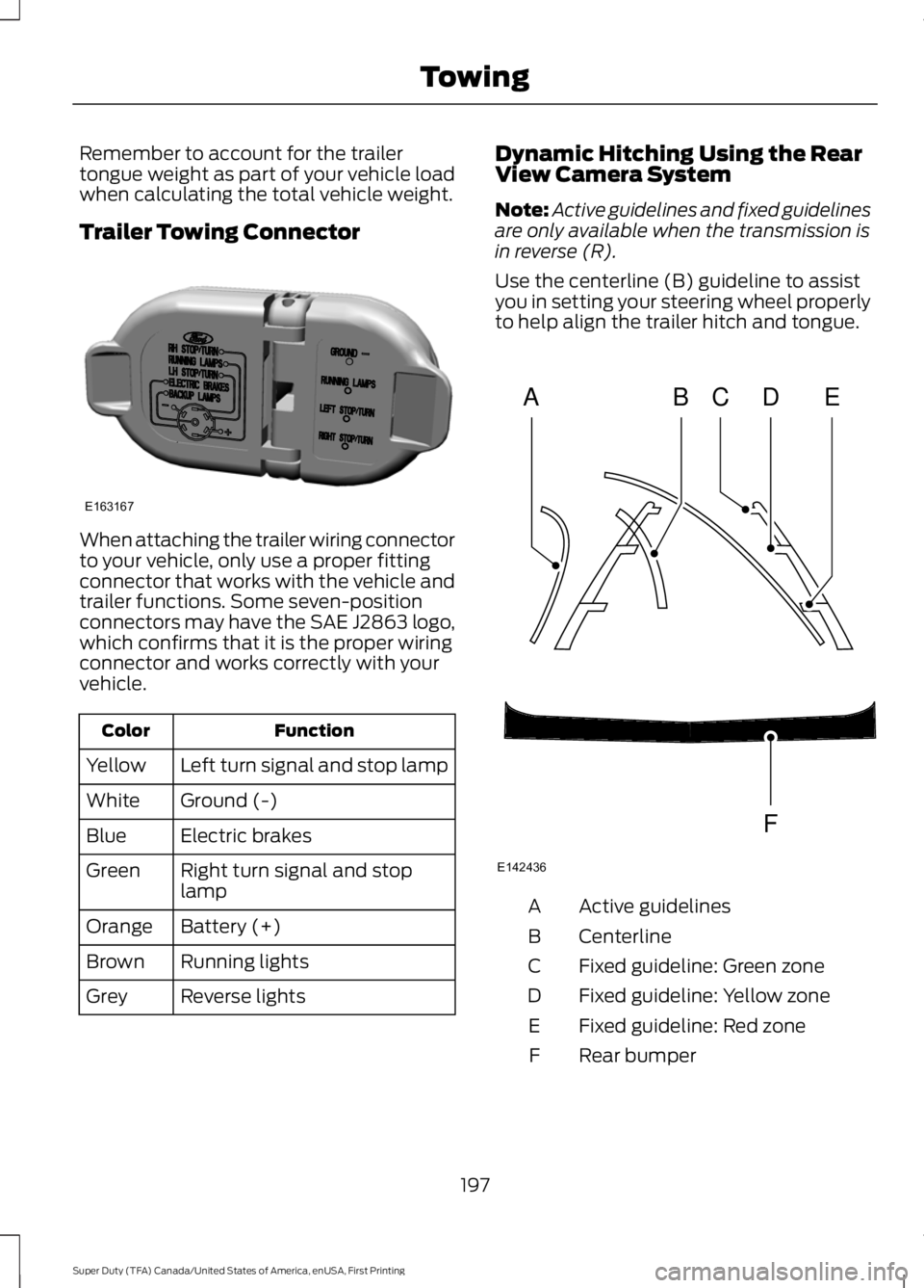
Trailer Towing Connector
When attaching the trailer wiring connectorto your vehicle, only use a proper fittingconnector that works with the vehicle andtrailer functions. Some seven-positionconnectors may have the SAE J2863 logo,which confirms that it is the proper wiringconnector and works correctly with yourvehicle.
FunctionColor
Left turn signal and stop lampYellow
Ground (-)White
Electric brakesBlue
Right turn signal and stoplampGreen
Battery (+)Orange
Running lightsBrown
Reverse lightsGrey
Dynamic Hitching Using the RearView Camera System
Note:Active guidelines and fixed guidelinesare only available when the transmission isin reverse (R).
Use the centerline (B) guideline to assistyou in setting your steering wheel properlyto help align the trailer hitch and tongue.
Active guidelinesA
CenterlineB
Fixed guideline: Green zoneC
Fixed guideline: Yellow zoneD
Fixed guideline: Red zoneE
Rear bumperF
197
Super Duty (TFA) Canada/United States of America, enUSA, First Printing
TowingE163167 ABCD
F
E
E142436
Page 201 of 507
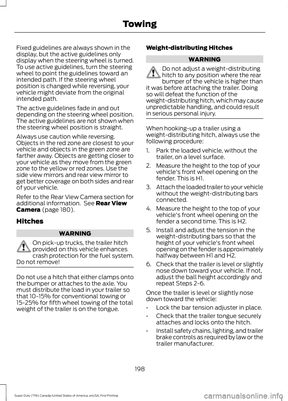
Fixed guidelines are always shown in thedisplay, but the active guidelines onlydisplay when the steering wheel is turned.To use active guidelines, turn the steeringwheel to point the guidelines toward anintended path. If the steering wheelposition is changed while reversing, yourvehicle might deviate from the originalintended path.
The active guidelines fade in and outdepending on the steering wheel position.The active guidelines are not shown whenthe steering wheel position is straight.
Always use caution while reversing.Objects in the red zone are closest to yourvehicle and objects in the green zone arefarther away. Objects are getting closer toyour vehicle as they move from the greenzone to the yellow or red zones. Use theside view mirrors and rear view mirror toget better coverage on both sides and rearof your vehicle.
Refer to the Rear View Camera section foradditional information. See Rear ViewCamera (page 180).
Hitches
WARNING
On pick-up trucks, the trailer hitchprovided on this vehicle enhancescrash protection for the fuel system.Do not remove!
Do not use a hitch that either clamps ontothe bumper or attaches to the axle. Youmust distribute the load in your trailer sothat 10-15% for conventional towing or15-25% for fifth wheel towing of the totalweight of the trailer is on the tongue.
Weight-distributing Hitches
WARNING
Do not adjust a weight-distributinghitch to any position where the rearbumper of the vehicle is higher thanit was before attaching the trailer. Doingso will defeat the function of theweight-distributing hitch, which may causeunpredictable handling, and could resultin serious personal injury.
When hooking-up a trailer using aweight-distributing hitch, always use thefollowing procedure:
1. Park the loaded vehicle, without thetrailer, on a level surface.
2. Measure the height to the top of yourvehicle's front wheel opening on thefender. This is H1.
3.Attach the loaded trailer to your vehiclewithout the weight-distributing barsconnected.
4. Measure the height to the top of yourvehicle's front wheel opening on thefender a second time. This is H2.
5. Install and adjust the tension in theweight-distributing bars so that theheight of your vehicle's front wheelopening on the fender is approximatelyhalfway between H1 and H2.
6.Check that the trailer is level or slightlynose down toward your vehicle. If not,adjust the ball height accordingly andrepeat Steps 2-6.
Once the trailer is level or slightly nosedown toward the vehicle:
•Lock the bar tension adjuster in place.
•Check that the trailer tongue securelyattaches and locks onto the hitch.
•Install safety chains, lighting, and trailerbrake controls as required by law or thetrailer manufacturer.
198
Super Duty (TFA) Canada/United States of America, enUSA, First Printing
Towing
Page 202 of 507
Fifth-wheel Trailer Hitch (If Equipped)
WARNINGS
The mounting pads in the bed arespecifically designed for certainfifth-wheel trailer hitches andgooseneck ball hitches. Do not use thesemounting pads for other purposes. Doingso could result in vehicle structuraldamage, loss of vehicle control, andpersonal injury. Contact an authorizeddealer to purchase gooseneck andfifth-wheel hitches that are compatiblewith your vehicle.
Towing trailers beyond the maximumlimit of the towing system couldresult in vehicle structural damage,loss of vehicle control and personal injury.
The hitch rating listed on the trailerhitch label is the maximum possibletrailer rating. To find the maximumtrailer weight allowed for your specificvehicle, consult an authorized dealer or theRV & Trailer Towing Guide provided by anauthorized dealer.
Your vehicle may be equipped with afifth-wheel prep package. This packageenables your vehicle to accept certainfifth-wheel trailer hitches and gooseneckball hitches. The fifth-wheel trailer hitchattaches to the four mounting pads in thepick-up bed. An optional 7-pin trailer wiringconnector may be in the bed as well. Thegooseneck ball hitch is a separatemounting pad from the fifth-wheel hitch,located in the center of the bed.
Shorter pick-up boxes, such as the 6½-footbox on the F-250 and F-350, provide lessclearance between the cab and thefifth-wheel and gooseneck trailercompared to longer box pick-ups, such asan 8-foot box on the F-250 or F-350. Whenselecting a trailer and tow vehicle, it iscritical to check that this combinationprovides clearance between the front of
the trailer and tow vehicle for turns up to90 degrees. Failure to follow thisrecommendation could result in the trailercontacting the cab of the tow vehicleduring tight turns that are typical duringlow-speed parking and turning maneuvers.This contact could result in damage to thetrailer and tow vehicle.
Safety Chains
Note:Do not attach safety chains to thebumper.
Always connect the safety chains to theframe or hook retainers of your vehiclehitch.
To connect the safety chains, cross thechains under the trailer tongue and allowenough slack for turning tight corners. Donot allow the chains to drag on the ground.
Trailer Brakes
WARNING
Do not connect a trailer's hydraulicbrake system directly to yourvehicle's brake system. Your vehiclemay not have enough braking power andyour chances of having a collision greatlyincrease.
Electric brakes and manual, automatic orsurge-type trailer brakes are safe if youinstall them properly and adjust them tothe manufacturer's specifications. Thetrailer brakes must meet local and federalregulations.
The rating for the tow vehicle's brakingsystem operation is at the gross vehicleweight rating, not the gross combinedweight rating.
Separate functioning brake systemsare required for safe control of towedvehicles and trailers weighing morethan 1500 pounds (680 kilograms)when loaded.
199
Super Duty (TFA) Canada/United States of America, enUSA, First Printing
Towing