2016 FORD F450 SUPER DUTY headlamp
[x] Cancel search: headlampPage 144 of 507
STARTING A GASOLINE
ENGINE
When you start the engine, the idle speedincreases, this helps to warm up theengine. If the engine idle speed does notslow down automatically, have yourvehicle checked by an authorized dealer.
Before starting the engine check thefollowing:
•Make sure all occupants have fastenedtheir safety belts.
•Make sure the headlamps andelectrical accessories are off.
•Make sure the parking brake is on.
•Move the transmission selector leverto position P.
•Turn the ignition key to the on position.
Note:Do not touch the accelerator pedal.
1. Fully press the brake pedal.
2. Turn the key to the start position tostart the engine. Release the key whenthe engine starts.
Note:The engine may continue crankingfor up to 15 seconds or until it starts.
Note:If you cannot start the engine on thefirst try, wait for a short period and try again.
Failure to Start
If you cannot start the engine after threeattempts, wait 10 seconds and follow thisprocedure:
1. Fully press the brake pedal.
2. Fully press the accelerator pedal andhold it there.
3. Start the engine.
Stopping the Engine When YourVehicle is Stationary
1. Move the transmission selector leverto position P.
2. Turn the key to the off position.
3. Apply the parking brake.
Stopping the Engine When YourVehicle is Moving
WARNING
Switching off the engine when thevehicle is still moving will result in aloss of brake and steering assistance.The steering will not lock, but higher effortwill be required. When the ignition isswitched off, some electrical circuits,including air bags, warning lamps andindicators may also be off. If the ignitionwas turned off accidentally, you can shiftinto neutral (N) and re-start the engine.
1. Move the transmission selector leverto position N and use the brakes tobring your vehicle to a safe stop.
2. When your vehicle has stopped, movethe transmission selector lever toposition P and turn the key to the offposition.
3. Apply the parking brake.
Cold Weather Starting (FlexibleFuel Vehicles Only)
The starting characteristics of all gradesof E85 ethanol make it unsuitable for usewhen ambient temperatures fall below0°F (-18°C). Consult your fuel distributorfor the availability of winter grade ethanol.As the outside temperature approachesfreezing, ethanol fuel distributors shouldsupply winter grade ethanol (same as withunleaded gasoline). If summer gradeethanol is used in cold weather conditions,0°F to 32°F (-18°C to 0°C), you mayexperience increased cranking times, roughidle or hesitation until the engine haswarmed up.
141
Super Duty (TFA) Canada/United States of America, enUSA, First Printing
Starting and Stopping the Engine
Page 232 of 507
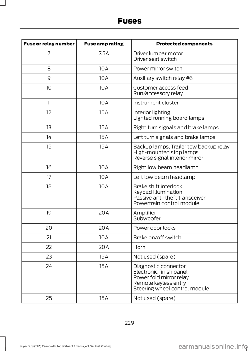
Protected componentsFuse amp ratingFuse or relay number
Driver lumbar motor7.5A7Driver seat switch
Power mirror switch10A8
Auxiliary switch relay #310A9
Customer access feed10A10Run/accessory relay
Instrument cluster10A11
Interior lighting15A12Lighted running board lamps
Right turn signals and brake lamps15A13
Left turn signals and brake lamps15A14
Backup lamps, Trailer tow backup relay15A15High-mounted stop lampsReverse signal interior mirror
Right low beam headlamp10A16
Left low beam headlamp10A17
Brake shift interlock10A18Keypad illuminationPassive anti-theft transceiverPowertrain control module
Amplifier20A19Subwoofer
Power door locks20A20
Brake on/off switch10A21
Horn20A22
Not used (spare)15A23
Diagnostic connector15A24Electronic finish panelPower fold mirror relayRemote keyless entrySteering wheel control module
Not used (spare)15A25
229
Super Duty (TFA) Canada/United States of America, enUSA, First Printing
Fuses
Page 233 of 507
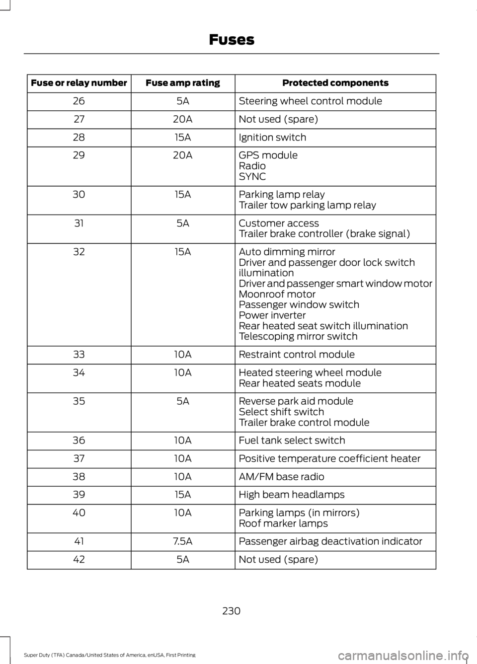
Protected componentsFuse amp ratingFuse or relay number
Steering wheel control module5A26
Not used (spare)20A27
Ignition switch15A28
GPS module20A29RadioSYNC
Parking lamp relay15A30Trailer tow parking lamp relay
Customer access5A31Trailer brake controller (brake signal)
Auto dimming mirror15A32Driver and passenger door lock switchilluminationDriver and passenger smart window motorMoonroof motorPassenger window switchPower inverterRear heated seat switch illuminationTelescoping mirror switch
Restraint control module10A33
Heated steering wheel module10A34Rear heated seats module
Reverse park aid module5A35Select shift switchTrailer brake control module
Fuel tank select switch10A36
Positive temperature coefficient heater10A37
AM/FM base radio10A38
High beam headlamps15A39
Parking lamps (in mirrors)10A40Roof marker lamps
Passenger airbag deactivation indicator7.5A41
Not used (spare)5A42
230
Super Duty (TFA) Canada/United States of America, enUSA, First Printing
Fuses
Page 250 of 507
CHECKING THE WIPER
BLADES
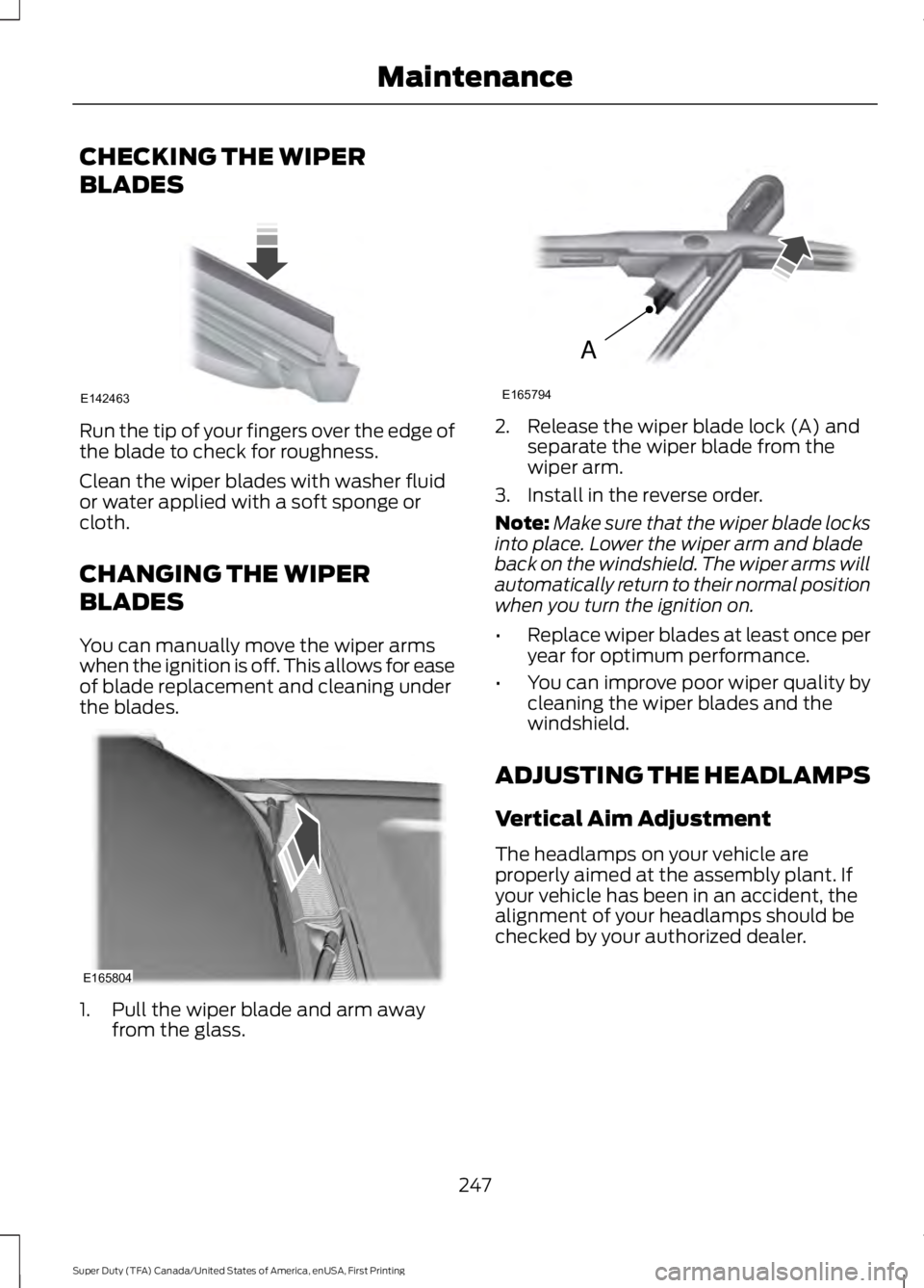
Run the tip of your fingers over the edge ofthe blade to check for roughness.
Clean the wiper blades with washer fluidor water applied with a soft sponge orcloth.
CHANGING THE WIPER
BLADES
You can manually move the wiper armswhen the ignition is off. This allows for easeof blade replacement and cleaning underthe blades.
1. Pull the wiper blade and arm awayfrom the glass.
2. Release the wiper blade lock (A) andseparate the wiper blade from thewiper arm.
3. Install in the reverse order.
Note:Make sure that the wiper blade locksinto place. Lower the wiper arm and bladeback on the windshield. The wiper arms willautomatically return to their normal positionwhen you turn the ignition on.
•Replace wiper blades at least once peryear for optimum performance.
•You can improve poor wiper quality bycleaning the wiper blades and thewindshield.
ADJUSTING THE HEADLAMPS
Vertical Aim Adjustment
The headlamps on your vehicle areproperly aimed at the assembly plant. Ifyour vehicle has been in an accident, thealignment of your headlamps should bechecked by your authorized dealer.
247
Super Duty (TFA) Canada/United States of America, enUSA, First Printing
MaintenanceE142463 E165804 A
E165794
Page 251 of 507
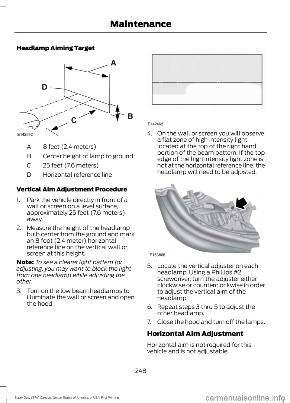
Headlamp Aiming Target
8 feet (2.4 meters)A
Center height of lamp to groundB
25 feet (7.6 meters)C
Horizontal reference lineD
Vertical Aim Adjustment Procedure
1. Park the vehicle directly in front of awall or screen on a level surface,approximately 25 feet (7.6 meters)away.
2. Measure the height of the headlampbulb center from the ground and markan 8 foot (2.4 meter) horizontalreference line on the vertical wall orscreen at this height.
Note:To see a clearer light pattern foradjusting, you may want to block the lightfrom one headlamp while adjusting theother.
3. Turn on the low beam headlamps toilluminate the wall or screen and openthe hood.
4. On the wall or screen you will observea flat zone of high intensity lightlocated at the top of the right handportion of the beam pattern. If the topedge of the high intensity light zone isnot at the horizontal reference line, theheadlamp will need to be adjusted.
5. Locate the vertical adjuster on eachheadlamp. Using a Phillips #2screwdriver, turn the adjuster eitherclockwise or counterclockwise in orderto adjust the vertical aim of theheadlamp.
6. Repeat steps 3 thru 5 to adjust theother headlamp.
7.Close the hood and turn off the lamps.
Horizontal Aim Adjustment
Horizontal aim is not required for thisvehicle and is not adjustable.
248
Super Duty (TFA) Canada/United States of America, enUSA, First Printing
MaintenanceE142592 E142465 E163806
Page 252 of 507
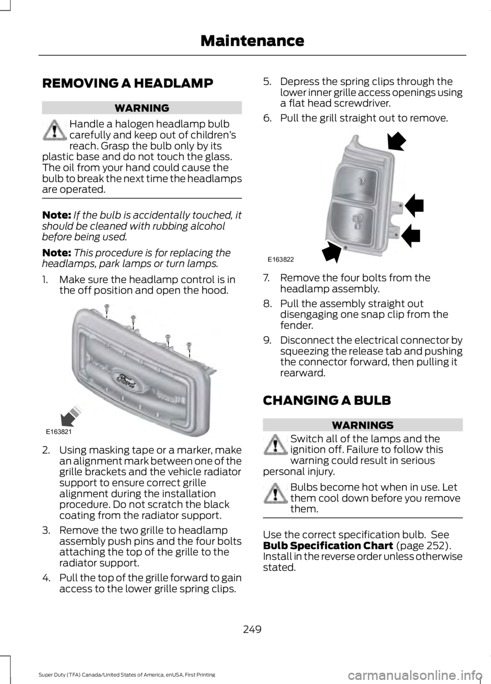
REMOVING A HEADLAMP
WARNING
Handle a halogen headlamp bulbcarefully and keep out of children’sreach. Grasp the bulb only by itsplastic base and do not touch the glass.The oil from your hand could cause thebulb to break the next time the headlampsare operated.
Note:If the bulb is accidentally touched, itshould be cleaned with rubbing alcoholbefore being used.
Note:This procedure is for replacing theheadlamps, park lamps or turn lamps.
1. Make sure the headlamp control is inthe off position and open the hood.
2.Using masking tape or a marker, makean alignment mark between one of thegrille brackets and the vehicle radiatorsupport to ensure correct grillealignment during the installationprocedure. Do not scratch the blackcoating from the radiator support.
3. Remove the two grille to headlampassembly push pins and the four boltsattaching the top of the grille to theradiator support.
4.Pull the top of the grille forward to gainaccess to the lower grille spring clips.
5. Depress the spring clips through thelower inner grille access openings usinga flat head screwdriver.
6. Pull the grill straight out to remove.
7. Remove the four bolts from theheadlamp assembly.
8. Pull the assembly straight outdisengaging one snap clip from thefender.
9.Disconnect the electrical connector bysqueezing the release tab and pushingthe connector forward, then pulling itrearward.
CHANGING A BULB
WARNINGS
Switch all of the lamps and theignition off. Failure to follow thiswarning could result in seriouspersonal injury.
Bulbs become hot when in use. Letthem cool down before you removethem.
Use the correct specification bulb. SeeBulb Specification Chart (page 252).Install in the reverse order unless otherwisestated.
249
Super Duty (TFA) Canada/United States of America, enUSA, First Printing
MaintenanceE163821 E163822
Page 253 of 507
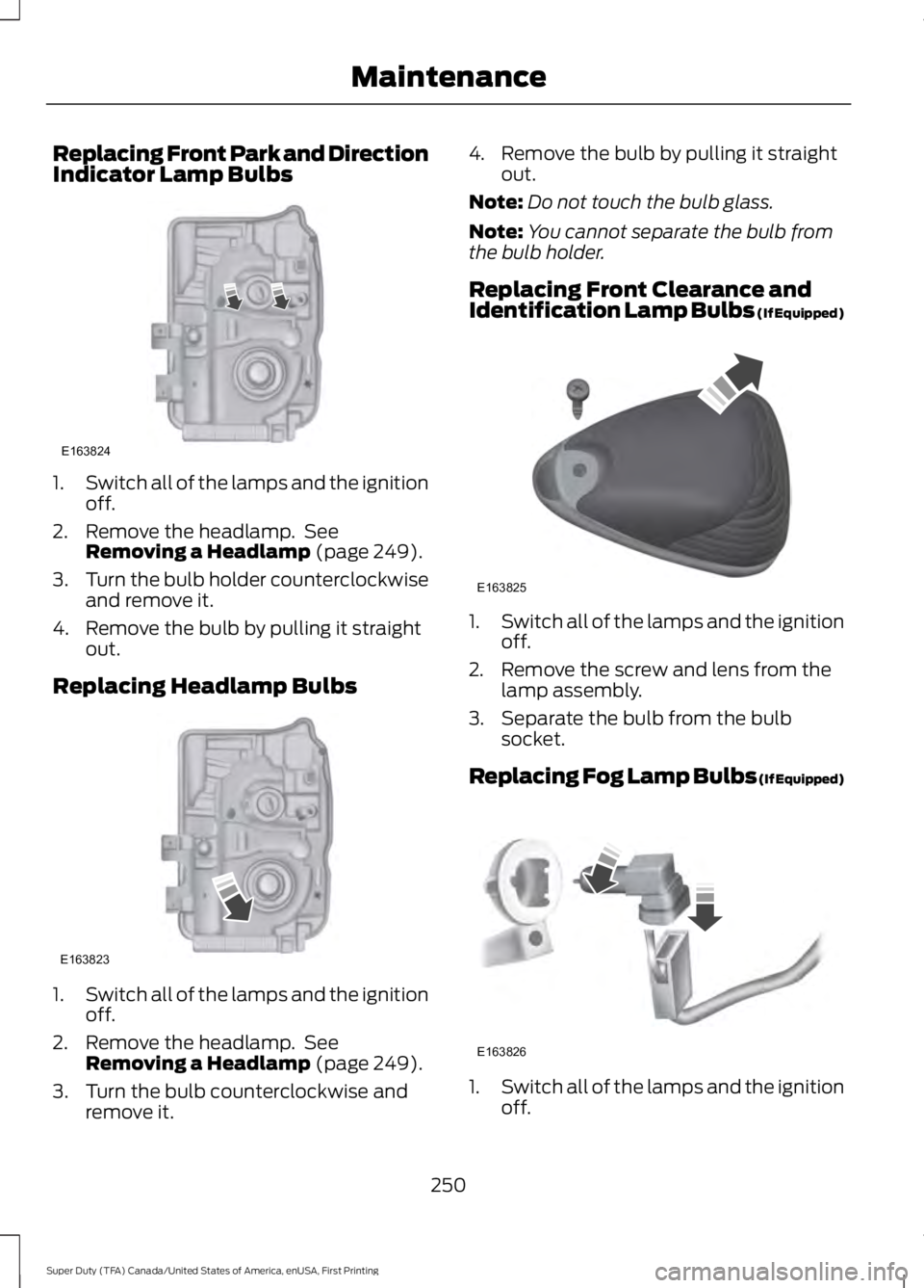
Replacing Front Park and DirectionIndicator Lamp Bulbs
1.Switch all of the lamps and the ignitionoff.
2. Remove the headlamp. SeeRemoving a Headlamp (page 249).
3.Turn the bulb holder counterclockwiseand remove it.
4. Remove the bulb by pulling it straightout.
Replacing Headlamp Bulbs
1.Switch all of the lamps and the ignitionoff.
2. Remove the headlamp. SeeRemoving a Headlamp (page 249).
3. Turn the bulb counterclockwise andremove it.
4. Remove the bulb by pulling it straightout.
Note:Do not touch the bulb glass.
Note:You cannot separate the bulb fromthe bulb holder.
Replacing Front Clearance andIdentification Lamp Bulbs (If Equipped)
1.Switch all of the lamps and the ignitionoff.
2. Remove the screw and lens from thelamp assembly.
3. Separate the bulb from the bulbsocket.
Replacing Fog Lamp Bulbs (If Equipped)
1.Switch all of the lamps and the ignitionoff.
250
Super Duty (TFA) Canada/United States of America, enUSA, First Printing
MaintenanceE163824 E163823 E163825 E163826
Page 255 of 507
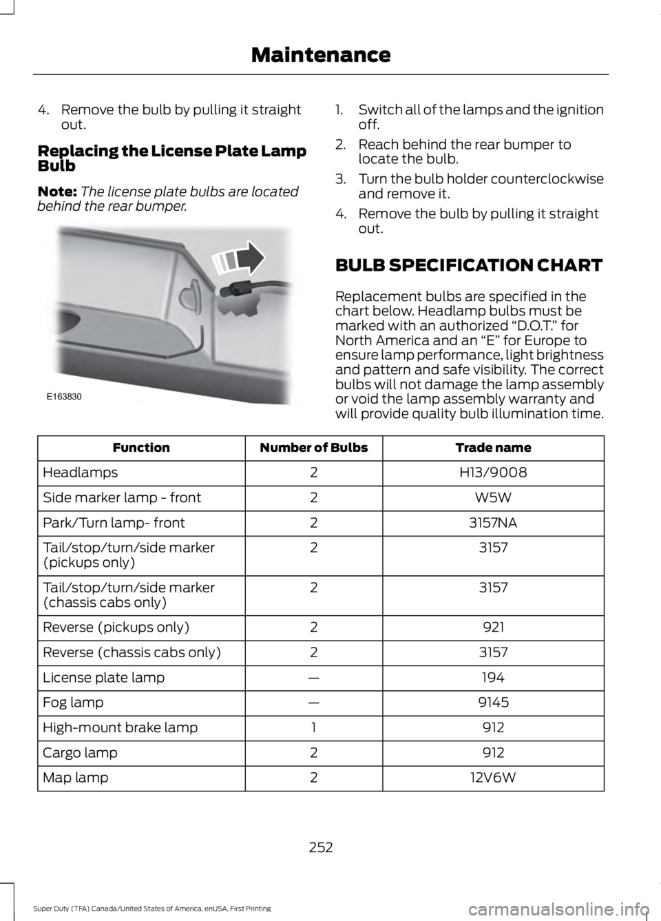
4. Remove the bulb by pulling it straightout.
Replacing the License Plate LampBulb
Note:The license plate bulbs are locatedbehind the rear bumper.
1.Switch all of the lamps and the ignitionoff.
2. Reach behind the rear bumper tolocate the bulb.
3.Turn the bulb holder counterclockwiseand remove it.
4. Remove the bulb by pulling it straightout.
BULB SPECIFICATION CHART
Replacement bulbs are specified in thechart below. Headlamp bulbs must bemarked with an authorized “D.O.T.” forNorth America and an “E” for Europe toensure lamp performance, light brightnessand pattern and safe visibility. The correctbulbs will not damage the lamp assemblyor void the lamp assembly warranty andwill provide quality bulb illumination time.
Trade nameNumber of BulbsFunction
H13/90082Headlamps
W5W2Side marker lamp - front
3157NA2Park/Turn lamp- front
31572Tail/stop/turn/side marker(pickups only)
31572Tail/stop/turn/side marker(chassis cabs only)
9212Reverse (pickups only)
31572Reverse (chassis cabs only)
194—License plate lamp
9145—Fog lamp
9121High-mount brake lamp
9122Cargo lamp
12V6W2Map lamp
252
Super Duty (TFA) Canada/United States of America, enUSA, First Printing
MaintenanceE163830