2016 FORD EXPEDITION ignition
[x] Cancel search: ignitionPage 257 of 421
Note:
For flexible fuel vehicles, if you are
operating on E85, you may experience poor
starts or an inability to start the engine and
driveability problems until the fuel trim and
ethanol content have been relearned.
Make sure that you dispose of old batteries
in an environmentally friendly way. Seek
advice from your local authority about
recycling old batteries.
If storing your vehicle for more than 30
days without recharging the battery, we
recommend that you disconnect the
battery cables to maintain battery charge
for quick starting.
Battery Management System (If
Equipped)
The battery management system monitors
battery conditions and takes actions to
extend battery life. If excessive battery
drain is detected, the system temporarily
disables some electrical systems to
protect the battery.
Systems included are:
• Heated rear window.
• Heated seats.
• Climate control.
• Heated steering wheel.
• Audio unit.
• Navigation system.
A message may appear in the information
displays to alert you that battery
protection actions are active. These
messages are only for notification that an
action is taking place, and not intended to
indicate an electrical problem or that the
battery requires replacement. After battery replacement, or in some
cases after charging the battery with an
external charger, the battery management
system requires eight hours of vehicle sleep
time to relearn the battery state of charge.
During this time your vehicle must remain
fully locked with the ignition switched off.
Note:
Prior to relearning the battery state
of charge, the battery management system
may temporarily disable some electrical
systems.
Electrical Accessory Installation
To make sure the battery management
system works correctly, do not connect an
electrical device ground connection
directly to the battery negative post. This
can cause inaccurate measurements of
the battery condition and potential
incorrect system operation.
Note: If you add electrical accessories or
components to the vehicle, it may adversely
affect battery performance and durability.
This may also affect the performance of
other electrical systems in the vehicle.
CHECKING THE WIPER
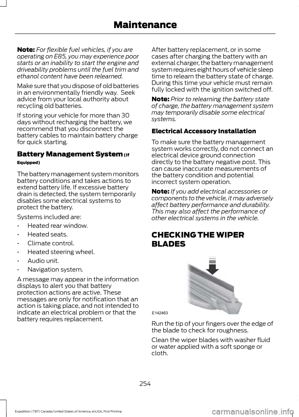
BLADES Run the tip of your fingers over the edge of
the blade to check for roughness.
Clean the wiper blades with washer fluid
or water applied with a soft sponge or
cloth.
254
Expedition (TB7) Canada/United States of America, enUSA, First Printing MaintenanceE142463
Page 259 of 421
Vertical Aim Adjustment
1. Park your vehicle directly in front of a
wall or screen on a level surface,
approximately 25 feet (7.6 meters)
away.
2. Measure the height from the center of your headlamp (indicated by a 3.0
millimeter circle on the lens) to the
ground and mark an 8 foot (2.4 meter)
horizontal reference line on the vertical
wall or screen at this height (a piece of
masking tape works well).
Note: To see a clearer light pattern for
adjusting, you may want to block the light
from one headlamp while adjusting the
other.
3. Switch on the low beam headlamps to
illuminate the wall or screen and open
the hood. Cover one of the headlamps
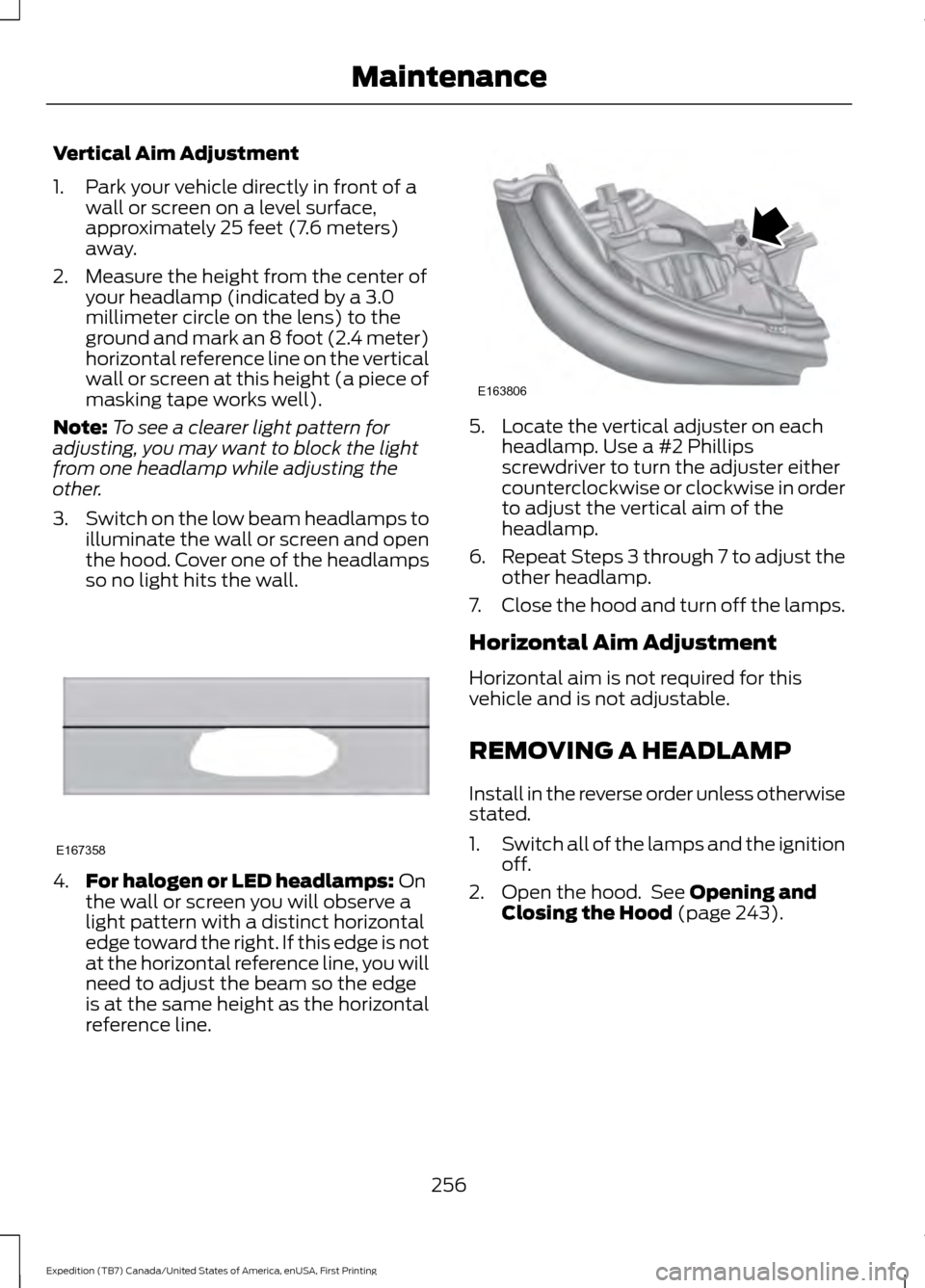
so no light hits the wall. 4.
For halogen or LED headlamps: On
the wall or screen you will observe a
light pattern with a distinct horizontal
edge toward the right. If this edge is not
at the horizontal reference line, you will
need to adjust the beam so the edge
is at the same height as the horizontal
reference line. 5. Locate the vertical adjuster on each
headlamp. Use a #2 Phillips
screwdriver to turn the adjuster either
counterclockwise or clockwise in order
to adjust the vertical aim of the
headlamp.
6. Repeat Steps 3 through 7 to adjust the
other headlamp.
7. Close the hood and turn off the lamps.
Horizontal Aim Adjustment
Horizontal aim is not required for this
vehicle and is not adjustable.
REMOVING A HEADLAMP
Install in the reverse order unless otherwise
stated.
1. Switch all of the lamps and the ignition
off.
2. Open the hood. See Opening and
Closing the Hood (page 243).
256
Expedition (TB7) Canada/United States of America, enUSA, First Printing MaintenanceE167358 E163806
Page 260 of 421
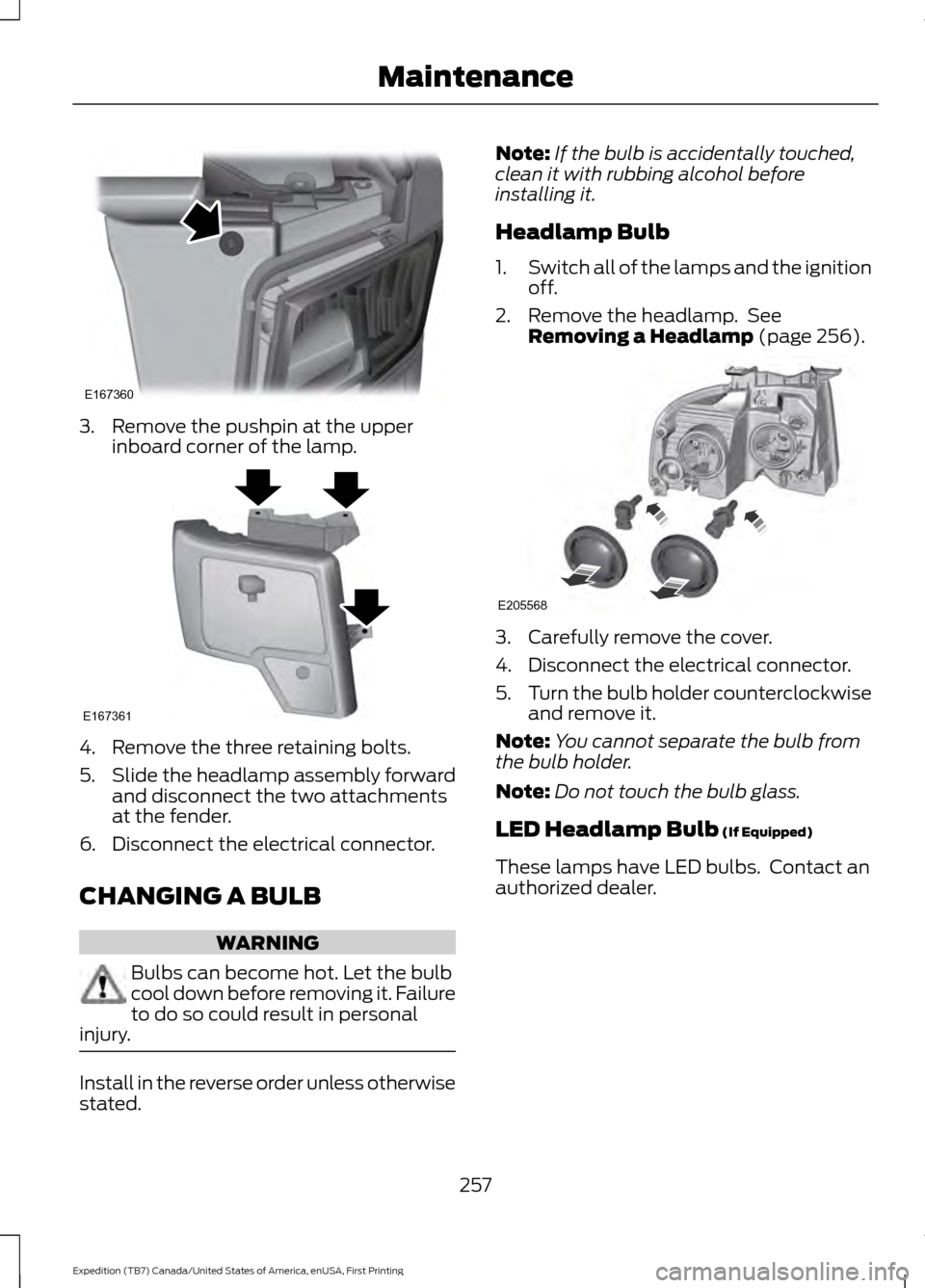
3. Remove the pushpin at the upper
inboard corner of the lamp. 4. Remove the three retaining bolts.
5.
Slide the headlamp assembly forward
and disconnect the two attachments
at the fender.
6. Disconnect the electrical connector.
CHANGING A BULB WARNING
Bulbs can become hot. Let the bulb
cool down before removing it. Failure
to do so could result in personal
injury. Install in the reverse order unless otherwise
stated. Note:
If the bulb is accidentally touched,
clean it with rubbing alcohol before
installing it.
Headlamp Bulb
1. Switch all of the lamps and the ignition
off.
2. Remove the headlamp. See Removing a Headlamp (page 256). 3. Carefully remove the cover.
4. Disconnect the electrical connector.
5.
Turn the bulb holder counterclockwise
and remove it.
Note: You cannot separate the bulb from
the bulb holder.
Note: Do not touch the bulb glass.
LED Headlamp Bulb
(If Equipped)
These lamps have LED bulbs. Contact an
authorized dealer.
257
Expedition (TB7) Canada/United States of America, enUSA, First Printing MaintenanceE167360 E167361 E205568
Page 261 of 421
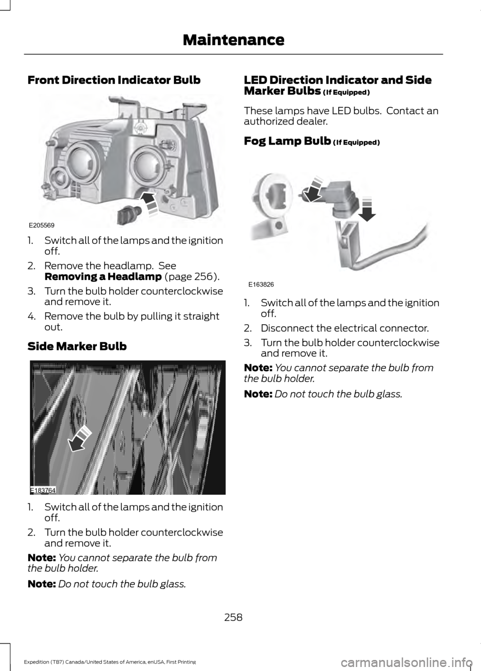
Front Direction Indicator Bulb
1.
Switch all of the lamps and the ignition
off.
2. Remove the headlamp. See Removing a Headlamp (page 256).
3. Turn the bulb holder counterclockwise
and remove it.
4. Remove the bulb by pulling it straight out.
Side Marker Bulb 1.
Switch all of the lamps and the ignition
off.
2. Turn the bulb holder counterclockwise
and remove it.
Note: You cannot separate the bulb from
the bulb holder.
Note: Do not touch the bulb glass. LED Direction Indicator and Side
Marker Bulbs
(If Equipped)
These lamps have LED bulbs. Contact an
authorized dealer.
Fog Lamp Bulb
(If Equipped) 1.
Switch all of the lamps and the ignition
off.
2. Disconnect the electrical connector.
3. Turn the bulb holder counterclockwise
and remove it.
Note: You cannot separate the bulb from
the bulb holder.
Note: Do not touch the bulb glass.
258
Expedition (TB7) Canada/United States of America, enUSA, First Printing MaintenanceE205569 E183764 E163826
Page 262 of 421
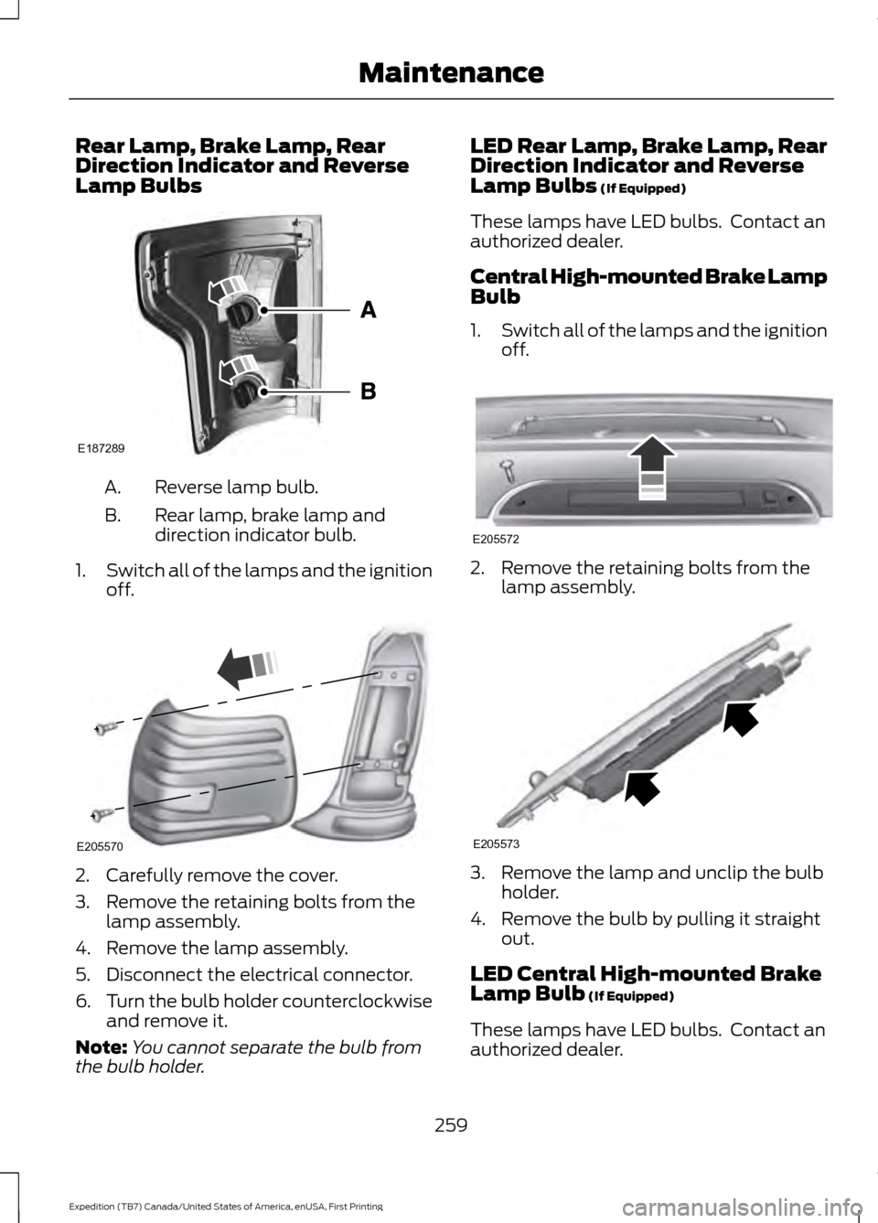
Rear Lamp, Brake Lamp, Rear
Direction Indicator and Reverse
Lamp Bulbs
Reverse lamp bulb.
A.
Rear lamp, brake lamp and
direction indicator bulb.
B.
1. Switch all of the lamps and the ignition
off. 2. Carefully remove the cover.
3. Remove the retaining bolts from the
lamp assembly.
4. Remove the lamp assembly.
5. Disconnect the electrical connector.
6. Turn the bulb holder counterclockwise
and remove it.
Note: You cannot separate the bulb from
the bulb holder. LED Rear Lamp, Brake Lamp, Rear
Direction Indicator and Reverse
Lamp Bulbs (If Equipped)
These lamps have LED bulbs. Contact an
authorized dealer.
Central High-mounted Brake Lamp
Bulb
1. Switch all of the lamps and the ignition
off. 2. Remove the retaining bolts from the
lamp assembly. 3. Remove the lamp and unclip the bulb
holder.
4. Remove the bulb by pulling it straight out.
LED Central High-mounted Brake
Lamp Bulb
(If Equipped)
These lamps have LED bulbs. Contact an
authorized dealer.
259
Expedition (TB7) Canada/United States of America, enUSA, First Printing MaintenanceE187289 E205570 E205572 E205573
Page 269 of 421
•
Never wash or rinse any ignition coil,
spark plug wire or spark plug well, or
the area in and around these locations.
• Cover the battery, power distribution
box, and air filter assembly to prevent
water damage when cleaning the
engine.
CLEANING THE WINDOWS AND
WIPER BLADES
Car wash chemicals and environmental
fallout can result in windshield and wiper
blade contamination. Dirty windshield and
wipers will result in poor windshield wiper
operation. Keep the windshield and wiper
blades clean to maintain windshield wiper
performance.
To clean the windshield and wiper blades:
• Clean the windshield with a
non-abrasive glass cleaner. When
cleaning the interior of the windshield,
avoid getting any glass cleaner on the
instrument panel or door panels. Wipe
any glass cleaner off these surfaces
immediately.
• For windshields contaminated with
tree sap, chemicals, wax or bugs, clean
the entire windshield using steel wool
(no greater than 0000 grade) in a
circular motion and rinse with water.
• Clean the wiper blades with isopropyl
rubbing alcohol or windshield washer
concentrate.
Note: Do not use razor blades or other
sharp objects to clean or remove decals
from the inside of the heated rear window.
The vehicle warranty does not cover
damage caused to the heated rear window
grid lines. CLEANING THE INTERIOR WARNINGS
Do not use cleaning solvents, bleach
or dye on the vehicle
’s safety belts,
as these actions may weaken the
belt webbing. On vehicles equipped with
seat-mounted airbags, do not use
chemical solvents or strong
detergents. Such products could
contaminate the side airbag system and
affect performance of the side airbag in a
collision. For fabric, carpets, cloth seats, safety belts
and seats equipped with side airbags:
•
Remove dust and loose dirt with a
vacuum cleaner.
• Remove light stains and soil with
Motorcraft Professional Strength
Carpet & Upholstery Cleaner.
• If grease or tar is present on the
material, spot-clean the area first with
Motorcraft Spot and Stain Remover. In
Canada, use Motorcraft Multi-Purpose
Cleaner.
• If a ring forms on the fabric after spot
cleaning, clean the entire area
immediately (but do not oversaturate)
or the ring will set.
• Do not use household cleaning
products or glass cleaners, which can
stain and discolor the fabric and affect
the flame retardant abilities of the seat
materials.
266
Expedition (TB7) Canada/United States of America, enUSA, First Printing Vehicle Care
Page 298 of 421

•
To reduce the chances of interference
from another vehicle, perform the
system reset procedure at least three
feet (one meter) away from another
Ford Motor Company vehicle
undergoing the system reset procedure
at the same time.
• Do not wait more than two minutes
between resetting each tire sensor or
the system will time-out and the entire
procedure will have to be repeated on
all four wheels.
• A double horn will sound indicating the
need to repeat the procedure.
Performing the System Reset Procedure
Read the entire procedure before
attempting.
1. Drive the vehicle above 20 mph (32 km/h) for at least two minutes, then
park in a safe location where you can
easily get to all four tires and have
access to an air pump.
2. Place the ignition in the off position and
keep the key in the ignition.
3. Cycle the ignition to the on position with the engine off.
4. Turn the hazard flashers on then off three times. You must accomplish this
within 10 seconds. If the reset mode
has been entered successfully, the horn
will sound once, the system indicator
will flash and a message is shown in
the information display. If this does not
occur, please try again starting at Step
2. If after repeated attempts to enter
the reset mode, the horn does not
sound, the system indicator does not
flash and no message is shown in the
information display, seek service from
your authorized dealer. 5. Train the tire pressure monitoring
system sensors in the tires using the
following system reset sequence
starting with the left front tire in the
following clockwise order: Left front
(driver's side front tire), Right front
(passenger's side front tire), Right rear
(passenger's side rear tire), Left rear
(driver's side rear tire).
6. Remove the valve cap from the valve stem on the left front tire. Decrease the
air pressure until the horn sounds.
Note: The single horn chirp confirms
that the sensor identification code has
been learned by the module for this
position. If a double horn is heard, the
reset procedure was unsuccessful, and
you must repeat it.
7. Remove the valve cap from the valve stem on the right front tire. Decrease
the air pressure until the horn sounds.
8. Remove the valve cap from the valve stem on the right rear tire. Decrease the
air pressure until the horn sounds.
9. Remove the valve cap from the valve stem on the left rear tire. Decrease the
air pressure until the horn sounds.
Training is complete after the horn
sounds for the last tire trained (driver's
side rear tire), the system indicator
stops flashing, and a message is shown
in the information display.
10. Turn the ignition off. If two short horn
beeps are heard, the reset procedure
was unsuccessful and you must
repeat it. If after repeating the
procedure and two short beeps are
heard when the ignition is turned to
off, seek assistance from your
authorized dealer.
295
Expedition (TB7) Canada/United States of America, enUSA, First Printing Wheels and Tires
Page 306 of 421

ENGINE SPECIFICATIONS
3.5L Ecoboost
Engine
214
Cubic inches
1-4-2-5-3-6
Firing order
Coil on plug
Ignition system
10.0:1
Compression ratio
0.030 in (0.75 mm) - 0.033 in (0.85 mm)
Spark plug gap
Drivebelt Routing MOTORCRAFT PARTS
Part Number
Component
FA-1883
Air filter element
FL-500-S
Oil filter
BXT-65-650
Battery (without Intelligent
Access)
BXT-65-750
Battery (with Intelligent Access)
SP-534
Spark plugs
303
Expedition (TB7) Canada/United States of America, enUSA, First Printing Capacities and SpecificationsE167467