Page 6 of 240
WARNINGS AND PRECAUTIONS
While reading this Owner Handbook you will find a series ofWARNINGSto prevent procedures that could damage your
vehicle.
There are alsoPRECAUTIONSthat must be carefully followed to prevent incorrect use of the components of the vehicle,
which could cause accidents or injuries.
Therefore allWARNINGSandPRECAUTIONSmust always be carefully followed.
WARNINGSandPRECAUTIONSare recalled in the text with the following symbols:
personal safety;
vehicle safety;
environmental protection.
NOTE These symbols, when necessary, are indicated besides the title or at the end of the line and are followed by a number.
That number recalls the corresponding warning at the end of the relevant section.
IMPORTANT
This Owner Handbook describes all vehicle versions. Options, equipment dedicated to specific markets or
versions are not explicitly indicated in the text: as a consequence, you should only consider the information which
is related to the trim level, engine and version that you have purchased. Any content introduced throughout the
production of the model, outside the specific request of options at the time of purchase, will be identified with the
wording(where provided).
All data contained in this publication are intended to help you use your vehicle in the best possible way. FCA Italy
S.p.A. aims at a constant improvement of the vehicles produced. For this reason it reserves the right to make
changes to the model described for technical and/or commercial reasons. For further information, contact a Fiat
Dealership.
VEHICLE CHANGES / ALTERATIONS
IMPORTANT Any change or alteration of the vehicle might seriously affect its safety and road holding, thus causing accidents,
in which the occupants could even be fatally injured.
4
Page 7 of 240
KNOWING YOUR CAR
KNOWING THE INSTRUMENT PANEL
SAFETY
STARTING AND DRIVING
IN AN EMERGENCY
SERVICING AND CARE
TECHNICAL DATA
MULTIMEDIA
INDEX
Page 139 of 240
compartment. Remove the adhesive
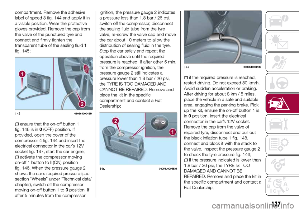
label of speed 3 fig. 144 and apply it in
a visible position. Wear the protective
gloves provided. Remove the cap from
the valve of the punctured tyre and
connect and firmly tighten the
transparent tube of the sealing fluid 1
fig. 145;
ensure that the on-off button 1
fig. 146 is in0(OFF) position. If
provided, open the cover of the
compressor 4 fig. 144 and insert the
electrical connector in the car’s 12V
socket fig. 147, start the car engine;
activate the compressor moving
on-off 1 button toI(ON) position
fig. 146. When the pressure gauge 2
shows the car’s required pressure (see
section “Wheels” under “Technical data”
chapter), switch off the compressor
moving on-off button 1 to0position. If
after 5 minutes from the compressorignition, the pressure gauge 2 indicates
a pressure less than 1.8 bar / 26 psi,
switch off the compressor, disconnect
the sealing fluid tube from the tyre
valve, re-screw the valve cap and move
the car about 10 meters to allow the
distribution of sealing fluid in the tyre.
Stop the car safely and repeat the
operation above until the required
pressure is reached. If after other 5 min.
from the compressor ignition, the
pressure gauge 2 still indicates a
pressure lower than 1.8 bar / 26 psi,
the TYRE IS TOO DAMAGED AND
CANNOT BE REPAIRED. Remove and
place the kit in the specific
compartment and contact a Fiat
Dealership;
if the required pressure is reached,
restart driving. Do not exceed 80 km/h.
Avoid sudden acceleration or braking.
After driving for about 8 km / 5 miles,
place the vehicle in a safe and suitable
area, engaging the parking brake. Pick
up the kit, ensure the on-off button 1 is
in0position, insert the electrical
connector in the car’s 12V socket.
Remove the cap from the valve of
repaired tyre, disconnect and pull out
the black inflation tube 1 fig. 148,
connect and block it with the stack to
the valve. Inspect the pressure gauge 2
to check the tyre pressure fig. 146;
if the pressure indicated is lower than
1.8 bar / 26 psi, the TYRE IS TOO
DAMAGED AND CANNOT BE
REPAIRED. Remove and place the kit in
the specific compartment and contact a
Fiat Dealership;
14508056J0004EM
14608056J0005EM
14708056J0002EM
137
Page 170 of 240
TECHNICAL DATA
Everything you may find useful for
understanding how your vehicle is
made and works is contained in this
chapter and illustrated with data, tables
and graphics. For the enthusiasts and
the technician, but also just for those
who want to know every detail of their
vehicle.
IDENTIFICATION DATA.........169
ENGINE..................170
WHEELS.................172
DIMENSIONS..............175
WEIGHTS.................176
REFUELLING...............178
FLUIDS AND LUBRICANTS......180
PERFORMANCE............183
FUEL CONSUMPTION.........184
CO2 EMISSIONS............186
PRESCRIPTIONS FOR HANDLING
THE VEHICLE AT THE END OF ITS
LIFE....................187
168
TECHNICAL DATA
Page 171 of 240
IDENTIFICATION
DATA
VEHICLE IDENTIFICATION
NUMBER (VIN) PLATE
It is located on the driver's door pillar. It
can be read with the door open and
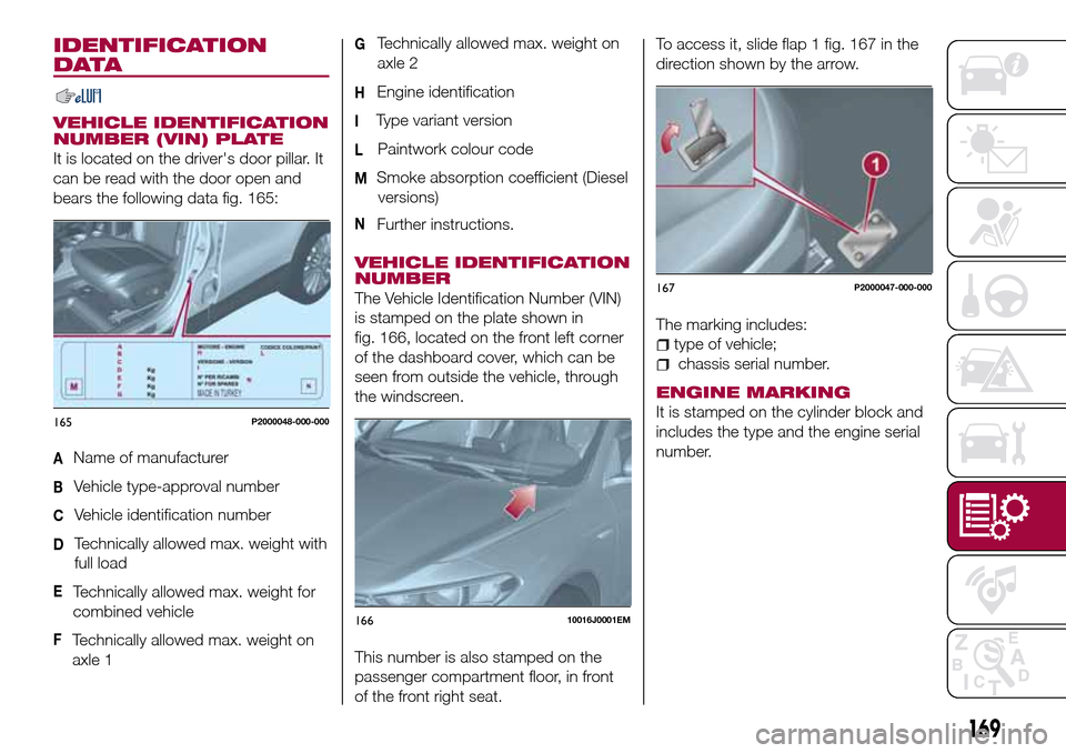
bears the following data fig. 165:
AName of manufacturer
BVehicle type-approval number
CVehicle identification number
DTechnically allowed max. weight with
full load
ETechnically allowed max. weight for
combined vehicle
FTechnically allowed max. weight on
axle 1
GTechnically allowed max. weight on
axle 2
HEngine identification
IType variant version
LPaintwork colour code
MSmoke absorption coefficient (Diesel
versions)
NFurther instructions.
VEHICLE IDENTIFICATION
NUMBER
The Vehicle Identification Number (VIN)
is stamped on the plate shown in
fig. 166, located on the front left corner
of the dashboard cover, which can be
seen from outside the vehicle, through
the windscreen.
This number is also stamped on the
passenger compartment floor, in front
of the front right seat.To access it, slide flap 1 fig. 167 in the
direction shown by the arrow.
The marking includes:
type of vehicle;
chassis serial number.
ENGINE MARKING
It is stamped on the cylinder block and
includes the type and the engine serial
number.165P2000048-000-000
16610016J0001EM
167P2000047-000-000
169
Page 172 of 240
ENGINE
172)
Versions 1.4 16V 95 HP 1.4 T-jet 120 HP
Engine code 843A1000 940B7000
Cycle Otto Otto
Number and position of cylinders 4 in line 4 in line
Piston bore and stroke (mm) 72 × 84 72 × 84
Total displacement (cm³) 1368 1368
Compression ratio 11 ± 0.2 9.8:1
Maximum power (EC) (kW) 70 88
corresponding engine speed (rpm) 6000 5000
Maximum torque (EC) (Nm) 127 215
corresponding engine speed (rpm) 4500 2500
Spark plugs NGK DCPR7E-N-10 NGK IKR9J8
FuelUnleaded petrol with R.O.N. no lower than
95 (EN 228 specifications)Unleaded petrol with R.O.N. no lower than
95 (EN 228 specifications)
170
TECHNICAL DATA
Page 174 of 240
WHEELS
SNOW TYRES
173)
Use snow tyres of the same size as the
standard tyres provided with the car.
The Fiat Dealership will be happy to
provide advice concerning the most
suitable type of tyre for the customer's
requirements.
For the type of snow tyre to be used,
inflation pressures and the
specifications of the tyres, carefully
follow the instructions given in this
chapter.
The winter features of these tyres are
reduced considerably when the tread
depth is below 4 mm. Replace them in
this case.
Due to the specific characteristics of
snow tyres, in normal weather
conditions or on long motorway
journeys, the performance of these
tyres is lower than that of standard
tyres.
Their usage should therefore be
restricted in accordance with their
type-approval; always comply with
specific local regulations relating to the
use of snow tyres.All four tyres should be the same (brand
and track) to ensure greater safety
when driving and braking as well as a
good manoeuvrability. Remember that
you should not change the rotation
direction of the tyres.
172
TECHNICAL DATA
Page 176 of 240
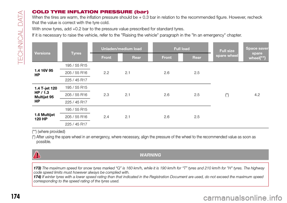
COLD TYRE INFLATION PRESSURE (bar)
When the tires are warm, the inflation pressure should be + 0.3 bar in relation to the recommended figure. However, recheck
that the value is correct with the tyre cold.
With snow tyres, add +0.2 bar to the pressure value prescribed for standard tyres.
If it is necessary to raise the vehicle, refer to the "Raising the vehicle" paragraph in the "In an emergency" chapter.
Versions TyresUnladen/medium load Full load
Full size
spare wheelSpace saver
spare
wheel(**)Front Rear Front Rear
1.4 16V 95
HP195 / 55 R15
2.2 2.1 2.6 2.5
(*)4.2 205 / 55 R16
225 / 45 R17
1.4 T-jet 120
HP / 1.3
Multijet 95
HP195 / 55 R15
2.3 2.1 2.6 2.5 205 / 55 R16
225 / 45 R17
1.6 Multijet
120 HP195 / 55 R15
2.4 2.1 2.6 2.5 205 / 55 R16
225 / 45 R17
(**) (where provided)
(*) After using the spare wheel in an emergency, where necessary, align the pressure of the wheel to the recommended value as soon as
possible.
WARNING
173)The maximum speed for snow tyres marked “Q” is 160 km/h, while it is 190 km/h for “T” tyres and 210 km/h for "H" tyres. The highway
code speed limits must however always be complied with.
174)If winter tyres with a lower speed rating than that indicated in the Registration Document are used, do not exceed the maximum speed
corresponding to the speed rating of the tyres used.
174
TECHNICAL DATA