2016 FIAT TIPO 5DOORS STATION WAGON spare wheel
[x] Cancel search: spare wheelPage 135 of 240
CHANGING A WHEEL
JACK
Please note that:
the jack weight is 2.15 kg;
the jack cannot be repaired and in
the event of a fault it must be replaced
by another genuine one;
No tool other than its cranking device
may be fitted on the jack.
Servicing
Prevent any dirt from depositing on
the "worm screw";
Keep the "worm screw" lubricated;
Never modify the jack.
Conditions for non-use
Temperatures below −40°C;
On sandy or muddy ground;
On uneven ground;
On steep roads;
In extreme weather conditions:
thunderstorms, typhoons, hurricanes,
blizzards, storms, etc.
In direct contact with the engine or
for repairs under the vehicle;
On boats.
CHANGING PROCEDURE
135) 136) 137) 138) 139)
49) 50)
Proceed as follows:
stop the car in a position that is not
dangerous for oncoming traffic where
you can change the wheel safely. The
ground must be flat and sufficiently
compact;
stop the engine, engage the hazard
warning lights and the parking brake;
engage first gear or reverse;
wear the reflective safety jacket
before getting out of the car (anyway
comply with the laws in force in the
country you are driving in);
open the boot and if there is a cargo
box, remove it as described in the
“Cargo box” paragraph in the “Getting
to know the car” chapter.
lift the mat and fix it by the tab to the
fastening device on the parcel shelf
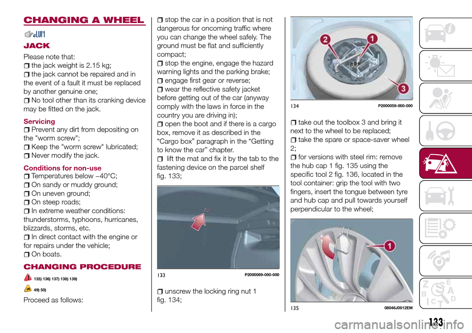
fig. 133;
unscrew the locking ring nut 1
fig. 134;
take out the toolbox 3 and bring it
next to the wheel to be replaced;
take the spare or space-saver wheel
2;
for versions with steel rim: remove
the hub cap 1 fig. 135 using the
specific tool 2 fig. 136, located in the
tool container: grip the tool with two
fingers, insert the tongue between tyre
and hub cap and pull towards yourself
perpendicular to the wheel;
133P2000069-000-000
134P2000059-000-000
13508046J0012EM
133
Page 136 of 240
loosen the bolt of the wheel to be
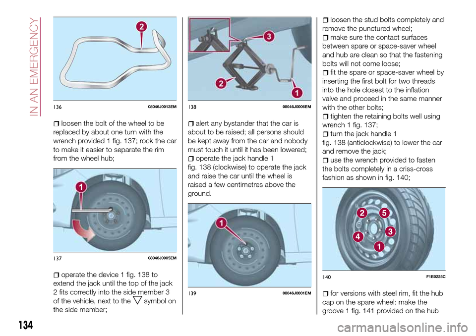
replaced by about one turn with the
wrench provided 1 fig. 137; rock the car
to make it easier to separate the rim
from the wheel hub;
operate the device 1 fig. 138 to
extend the jack until the top of the jack
2 fits correctly into the side member 3
of the vehicle, next to the
symbol on
the side member;
alert any bystander that the car is
about to be raised; all persons should
be kept away from the car and nobody
must touch it until it has been lowered;
operate the jack handle 1
fig. 138 (clockwise) to operate the jack
and raise the car until the wheel is
raised a few centimetres above the
ground.
loosen the stud bolts completely and
remove the punctured wheel;
make sure the contact surfaces
between spare or space-saver wheel
and hub are clean so that the fastening
bolts will not come loose;
fit the spare or space-saver wheel by
inserting the first bolt for two threads
into the hole closest to the inflation
valve and proceed in the same manner
with the other bolts;
tighten the retaining bolts well using
wrench 1 fig. 137;
turn the jack handle 1
fig. 138 (anticlockwise) to lower the car
and remove the jack;
use the wrench provided to fasten
the bolts completely in a criss-cross
fashion as shown in fig. 140;
for versions with steel rim, fit the hub
cap on the spare wheel: make the
groove 1 fig. 141 provided on the hub
13608046J0013EM
13708046J0005EM
13808046J0006EM
13908046J0001EM
140F1B0225C
134
IN AN EMERGENCY
Page 137 of 240
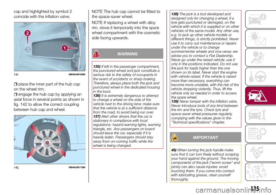
cap and highlighted by symbol 2
coincide with the inflation valve;
place the inner part of the hub cap
on the wheel rim;
engage the hub cap by applying an
axial force in several points as shown in
fig. 142 to allow the correct coupling
between hub cap and wheel.NOTE The hub cap cannot be fitted to
the space-saver wheel.
NOTE If replacing a wheel with alloy
rim, stove it temporarily into the spare
wheel compartment with the cosmetic
side facing upwards.
WARNING
135)If left in the passenger compartment,
the punctured wheel and jack constitute a
serious risk to the safety of occupants in
the event of accidents or sharp braking.
Therefore, always place both the jack and
punctured wheel in the dedicated housing
in the boot.
136)It is extremely dangerous to attempt
to change a wheel on the side of the
vehicle next to the driving lane: make sure
that the vehicle is at a sufficient distance
from the road, to avoid being run over.
137)Alert other drivers that the car is
stationary in compliance with local
regulations: hazard warning lights, warning
triangle, etc. Any passengers on board
should leave the car, especially if it is
heavily laden. Passengers should stay
away from on-coming traffic while the
wheel is being changed.138)The jack is a tool developed and
designed only for changing a wheel, if a
tyre gets punctured or damaged, on the
vehicle with which it is supplied or on other
vehicles of the same model. Any other use,
e.g. to jack up other vehicle models or
different things, is strictly prohibited. Never
use it to carry out maintenance or repairs
under the vehicle or to change
summer/winter wheels and vice versa: we
advise you to contact a Fiat Dealership.
Never go under the raised vehicle: use it
only in the positions indicated. Do not use
the jack for loads higher than the one
shown on its label. Never start the engine
with vehicle raised. If the vehicle is raised
more than necessary, everything can
become more unstable, with the risk of the
vehicle dropping violently. Thus, lift the
vehicle only as needed in order to access
the spare wheel.
139)Never tamper with the inflation valve.
Never introduce tools of any kind between
the rim and the tyre. Check tyre and
space-saver wheel pressures regularly,
complying with the values given in the
"Technical specifications" chapter.
IMPORTANT
49)When turning the jack handle make
sure that it can turn freely without scraping
your hand against the ground. The moving
components of the jack ("worm screw" and
joints) can also cause injuries: avoid
touching them. If you come into contact
with lubricating grease, clean yourself
thoroughly.
14108046J0010EM
14208046J0011EM
135
Page 139 of 240
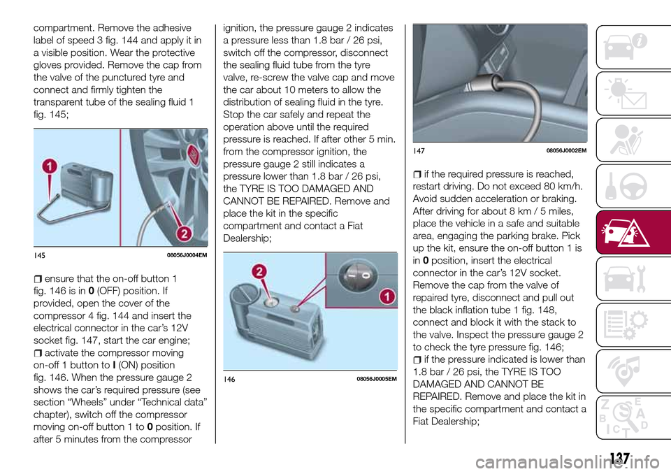
compartment. Remove the adhesive
label of speed 3 fig. 144 and apply it in
a visible position. Wear the protective
gloves provided. Remove the cap from
the valve of the punctured tyre and
connect and firmly tighten the
transparent tube of the sealing fluid 1
fig. 145;
ensure that the on-off button 1
fig. 146 is in0(OFF) position. If
provided, open the cover of the
compressor 4 fig. 144 and insert the
electrical connector in the car’s 12V
socket fig. 147, start the car engine;
activate the compressor moving
on-off 1 button toI(ON) position
fig. 146. When the pressure gauge 2
shows the car’s required pressure (see
section “Wheels” under “Technical data”
chapter), switch off the compressor
moving on-off button 1 to0position. If
after 5 minutes from the compressorignition, the pressure gauge 2 indicates
a pressure less than 1.8 bar / 26 psi,
switch off the compressor, disconnect
the sealing fluid tube from the tyre
valve, re-screw the valve cap and move
the car about 10 meters to allow the
distribution of sealing fluid in the tyre.
Stop the car safely and repeat the
operation above until the required
pressure is reached. If after other 5 min.
from the compressor ignition, the
pressure gauge 2 still indicates a
pressure lower than 1.8 bar / 26 psi,
the TYRE IS TOO DAMAGED AND
CANNOT BE REPAIRED. Remove and
place the kit in the specific
compartment and contact a Fiat
Dealership;
if the required pressure is reached,
restart driving. Do not exceed 80 km/h.
Avoid sudden acceleration or braking.
After driving for about 8 km / 5 miles,
place the vehicle in a safe and suitable
area, engaging the parking brake. Pick
up the kit, ensure the on-off button 1 is
in0position, insert the electrical
connector in the car’s 12V socket.
Remove the cap from the valve of
repaired tyre, disconnect and pull out
the black inflation tube 1 fig. 148,
connect and block it with the stack to
the valve. Inspect the pressure gauge 2
to check the tyre pressure fig. 146;
if the pressure indicated is lower than
1.8 bar / 26 psi, the TYRE IS TOO
DAMAGED AND CANNOT BE
REPAIRED. Remove and place the kit in
the specific compartment and contact a
Fiat Dealership;
14508056J0004EM
14608056J0005EM
14708056J0002EM
137
Page 176 of 240
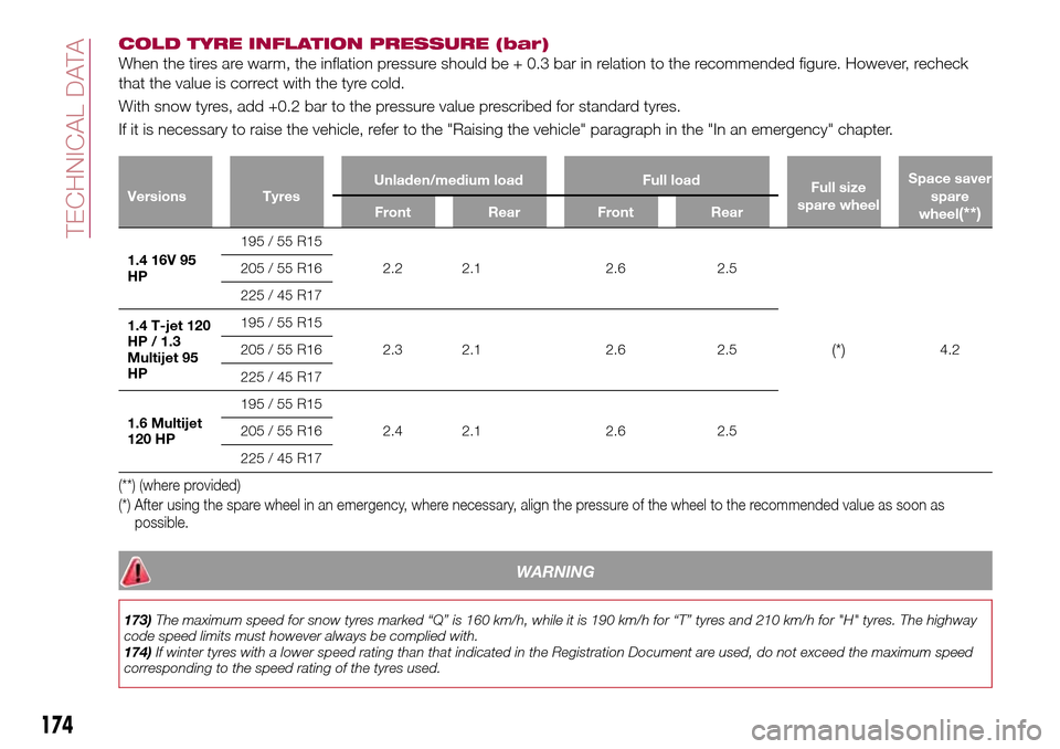
COLD TYRE INFLATION PRESSURE (bar)
When the tires are warm, the inflation pressure should be + 0.3 bar in relation to the recommended figure. However, recheck
that the value is correct with the tyre cold.
With snow tyres, add +0.2 bar to the pressure value prescribed for standard tyres.
If it is necessary to raise the vehicle, refer to the "Raising the vehicle" paragraph in the "In an emergency" chapter.
Versions TyresUnladen/medium load Full load
Full size
spare wheelSpace saver
spare
wheel(**)Front Rear Front Rear
1.4 16V 95
HP195 / 55 R15
2.2 2.1 2.6 2.5
(*)4.2 205 / 55 R16
225 / 45 R17
1.4 T-jet 120
HP / 1.3
Multijet 95
HP195 / 55 R15
2.3 2.1 2.6 2.5 205 / 55 R16
225 / 45 R17
1.6 Multijet
120 HP195 / 55 R15
2.4 2.1 2.6 2.5 205 / 55 R16
225 / 45 R17
(**) (where provided)
(*) After using the spare wheel in an emergency, where necessary, align the pressure of the wheel to the recommended value as soon as
possible.
WARNING
173)The maximum speed for snow tyres marked “Q” is 160 km/h, while it is 190 km/h for “T” tyres and 210 km/h for "H" tyres. The highway
code speed limits must however always be complied with.
174)If winter tyres with a lower speed rating than that indicated in the Registration Document are used, do not exceed the maximum speed
corresponding to the speed rating of the tyres used.
174
TECHNICAL DATA