2016 FIAT TIPO 4DOORS ECU
[x] Cancel search: ECUPage 97 of 204

TOWING TRAILERS
IMPORTANT NOTES
115) 116)
For towing caravans or trailers the
vehicle must be fitted with an approved
tow hook and an adequate electrical
system. Should aftermarket installation
be requested, this must be carried out
by specialists.
Install any specific and/or additional
door mirrors as specified by the
Highway Code.
Remember that, when towing a trailer,
steep hills are harder to climb, braking
distances increase and overtaking takes
longer depending on the overall weight
of the trailer.
Engage a low gear when driving
downhill, rather than constantly using
the brake.
The weight the trailer exerts on the
vehicle tow hook reduces the vehicle's
loading capacity by the same amount.
To make sure that the maximum
towable weight is not exceeded (given
in the vehicle registration document)
account should be taken of the fully
laden trailer, including accessories and
luggage.
Do not exceed the speed limits specific
to each country you are driving in, in thecase of vehicles towing trailers. In any
case, the top speed must not exceed
100 km/h.
Any electric brake must be powered
directly by the battery through a cable
with a cross-section of no less than 2.5
mm
2.
In addition to the electrical branches,
the vehicle electrical system can only be
connected to the supply cable for an
electric brake and to the cable for an
internal light for the trailer, not
exceeding 15 W. For connections, use
the preset control unit with a battery
cable with section not less than 2.5 mm
2.
IMPORTANT The use of auxiliary loads
other than external lights (e.g. electric
brake) must take place with engine
running.
INSTALLING A TOW
HOOK
The towing device should be fastened
to the body by specialised personnel
according to any additional and/or
integrative information supplied by the
Manufacturer of the device.
The towing device must meet current
regulations with reference to Directive
94/20/EC and subsequent
amendments.For any version the towing device used
must be right for the towable weight of
the vehicle on which it is to be installed.
For the electrical connection a standard
connector should be used which is
generally placed on a special bracket
normally fastened to the towing device,
and a special ECU for external trailer
light control must be installed on the
vehicle.
Seven or thirteen pin 12 V DC
connections should be used
(CUNA/UNI and ISO/DIN Standards).
Follow any instructions provided by the
vehicle manufacturer and/or the towing
device manufacturer.
WARNING
115)The ABS with which the car is
equipped will not control the braking
system of the trailer. Particular caution is
required on slippery roads.
116)Never modify the braking system of
the vehicle to control the trailer brake. The
trailer braking system must be fully
independent of the car’s hydraulic system.
95
Page 109 of 204

ENGINE COMPARTMENT
FUSE BOX
34)
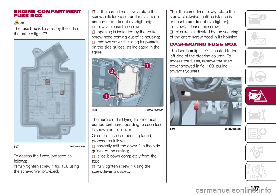
The fuse box is located by the side of
the battery fig. 107.
To access the fuses, proceed as
follows:
fully tighten screw 1 fig. 108 using
the screwdriver provided;
at the same time slowly rotate the
screw anticlockwise, until resistance is
encountered (do not overtighten);
slowly release the screw;
opening is indicated by the entire
screw head coming out of its housing;
remove cover 2, sliding it upwards
on the side guides, as indicated in the
figure.
The number identifying the electrical
component corresponding to each fuse
is shown on the cover.
Once the fuse has been replaced,
proceed as follows:
correctly refit the cover 2 in the side
guides of the casing;
slide it down completely from the
top;
fully tighten screw 1 using the
screwdriver provided;
at the same time slowly rotate the
screw clockwise, until resistance is
encountered (do not overtighten);
slowly release the screw;
closure is indicated by the securing
of the entire screw head in its housing.
DASHBOARD FUSE BOX
The fuse box fig. 110 is located to the
left side of the steering column. To
access the fuses, remove the snap
cover showed in fig. 109, pulling
towards yourself.
10708036J0005EM
10808036J0006EM
10906106J0005EM
107
Page 118 of 204

a visible position. Wear the protective
gloves provided. Remove the cap from
the valve of the punctured tyre and
connect and firmly tighten the
transparent tube of the sealing fluid 1
fig. 125;
ensure that the on-off button is in0
(OFF) position. If provided, open the
cover of the compressor 4 fig. 124 and
insert the electrical connector in the
12V socket of the vehicle fig. 126,
switch on the vehicle engine;
activate the compressor moving
on-off button toI(ON) position. When
the pressure gauge shows the vehicle
required pressure (see section “Wheels”
under “Technical data” chapter), switch
off the compressor moving on-off
button to0position. If after 5 minutes
from the compressor ignition, the
pressure gauge indicates a pressure
less than 1.8 bar / 26 psi, switch off thecompressor, disconnect the sealing
fluid tube from the tyre valve, re-screw
the valve cap and move the vehicle
about 10 meters to allow the
distribution of sealing fluid in the tyre.
Securely stop the vehicle and repeat
the operation above until reaching the
required pressure. If after other 5 min.
from the compressor ignition, the
pressure gauge still indicates a pressure
lower than 1.8 bar / 26 psi, the TYRE IS
TOO DAMAGED AND CANNOT BE
REPAIRED. Remove and place the kit in
the specific compartment and contact a
Fiat Dealership;
if the required pressure is reached,
restart driving. Do not exceed 80 km/h.
Avoid sudden acceleration or braking.
After driving for about 8 km / 5 miles,
place the vehicle in a safe and smooth
area, engaging the parking brake. Pick
up the kit, ensure the on-off button is in0position, insert the electrical
connector in the vehicle 12V socket.
Remove the cap from the valve of
repaired tyre, disconnect and pull out
the black inflation tube 1 fig. 127,
connect and block it with the stack to
the valve. Inspect the pressure gauge to
check the tyre pressure;
if the pressure indicated is lower than
1.8 bar / 26 psi, the TYRE IS TOO
DAMAGED AND CANNOT BE
REPAIRED. Remove and place the kit in
the specific compartment and contact a
Fiat Dealership;
if the pressure indicated is equal to or
higher than 1.8 bar / 26 psi, switch on
the compressor and reach the required
pressure. Disconnect and replace the
kit in the specific compartment.
Carefully drive and reach the Fiat
Dealership as soon as possible;
12508056J0004EM
12608056J0002EM
12708056J0006EM
116
IN AN EMERGENCY
Page 119 of 204

WARNING
133)The information required by the
applicable regulation is indicated on the
Fix&Go kit package label. Compliance with
the indications on the label is an essential
condition to ensure the safety and the
effectiveness of the Fix&Go kit. Carefully
read the label before use, avoid improper
use. Fix&Go is subject to expiration and
must be replaced periodically. The kit
should be used by adults and cannot be
used by children.
IMPORTANT
38)Show the package and the label to the
personnel charged with handling the tyre
treated with the tyre repair kit.
39)Fix&Go provides a temporary repair,
therefore the tyre must be examined and
repaired by a specialist as soon as
possible. The sealing fluid is effective at
temperatures between -40°C and +50°C. It
is possible to repair tyres which have been
damaged on tread up to a diameter of
4mm; however, tyres damaged on their
side cannot be repaired. Before using
Fix&Go kit, ensure that the tyre isn't
excessively damaged and that the rim is in
good condition, otherwise do not use it and
contact a Fiat Dealership. Do not remove
foreign bodies from the tyre. Do not let the
compressor turned on for more than 20
consecutive minutes - overheating hazard.
EMERGENCY
STARTING
If the battery is flat, a jump starting can
be performed using the battery and the
cables of another vehicle, or using an
auxiliary battery. In all cases, the battery
used must have a capacity equal to or
a little higher than the flat one.
40)
IMPORTANT NOTES
Do not use an auxiliary battery or any
other source of external supply with a
voltage above 12 V: the battery, the
starter, the alternator and the electrical
system of the vehicle could be
damaged.
Do not attempt jump starting if the
battery is frozen. The battery could
break and explode!
PREPARATION TO JUMP
STARTING
The vehicle battery is located in the
engine compartment, behind the left
light cluster.
134) 135) 136) 137)
IMPORTANT The positive terminal (+) of
the battery is shielded by a protective
element. Raise it to access the terminal.
Proceed as follows:
operate the parking brake, move the
lever to P (Park), for versions equipped
with automatic transmission (if present),
or neutral, for versions with manual
gearbox, then set the ignition device to
STOP;
switch off all the other electrical
devices in the vehicle;
should you be using the battery of
another vehicle, park the other vehicle
within the range of the cables used for
the connection, operate the parking
brake and ensure that its ignition is off.
IMPORTANT Never connect the
negative terminals of the two batteries
directly! If the auxiliary battery is
installed on another vehicle, check that
there is no accidental contact of metal
parts between the two vehicles, since
an earth connection may result, with
the risk of serious injury to any people
who may be nearby.
IMPORTANT If the procedure below is
carried out incorrectly, it can cause
severe injury to people or damage the
recharging system of one or both
vehicles. Carefully follow the
instructions given below.
Cable connection
41)
Proceed as follows to carry out a jump
starting fig. 128:
117
Page 141 of 204

152)When performing any operation on
the battery or near it, always protect your
eyes with special goggles.
IMPORTANT
43)Be careful not to confuse the various
types of fluids while topping up: they are
not compatible with each other! Topping up
with an unsuitable fluid could severely
damage your vehicle.
44)The oil level must never exceed the
MAX. mark.
45)Always top up using engine oil of the
same specifications as that already in the
engine.
46)PARAFLU
UPanti-freeze is used in the
engine cooling system. Use fluid of the
same type as that contained in the cooling
system for any top-ups. PARAFLU
UP
cannot be mixed with any other type of
fluid. If this happens, do not start the
engine under any circumstances and
contact a Fiat Dealership.
47)Prevent brake fluid, which is highly
corrosive, from coming into contact with
painted parts. Should it happen,
immediately wash with water.
48)If the vehicle must remain unused for a
long time at a very low temperature,
remove the battery and take it to a warm
place, to avoid freezing.49)Incorrect installation of electric and
electronic devices may cause severe
damage to your car. After purchasing your
vehicle, if you wish to install any
accessories (e.g. anti-theft, radio phone,
etc.), go to a Fiat Dealership, which will
suggest the most suitable devices and
advise you whether a higher capacity
battery needs to be installed.
IMPORTANT
2)The used engine oil and the filter that has
been replaced contain substances that are
harmful to the environment. To change the
oil and filters, we advise you to contact a
Fiat Dealership.
3)Used transmission fluid contains
substances that are harmful to the
environment. It is advisable to contact a
Fiat Dealership to have the fluid changed.
4)Batteries contain substances which are
very dangerous for the environment. For
battery replacement, contact a Fiat
Dealership.
BATTERY
RECHARGING
IMPORTANT NOTES
IMPORTANT The battery recharging
procedure is given as information only.
To carry out this operation contact a
Fiat Dealership.
IMPORTANT After setting the ignition
device to STOP and having closed the
driver side door, wait at least one
minute before disconnecting the
electrical supply from the battery. When
reconnecting the electrical supply to the
battery, make sure that the ignition
device is in the STOP position and the
driver side door is closed.
IMPORTANT Charging should be slow
at a low ampere rating for
approximately 24 hours. Charging for a
longer time may damage the battery.
IMPORTANT The cables of the
electrical system must be correctly
reconnected to the battery, i.e. the
positive cable (+) to the positive
terminal and the negative cable (–) to
the negative terminal. The battery
terminals are marked with the positive
(+) and negative (–) symbols, and are
shown on the battery cover. The battery
terminals must also be corrosion-free
and firmly secured to the terminals. If a
139