2016 FIAT DUCATO in out
[x] Cancel search: in outPage 174 of 296

with the tools assembled, undo the
bolts fig. 164 fully and remove the
wheel;
fit the spare wheel, lining up the
holes G fig. 165 with the corresponding
pins H. While fitting the spare wheel,
make sure that the mating surfaces are
clean and free of impurities that could
later cause the fixing bolts to come
loose;
screw in the 5 fastening bolts;
assemble the tools to tighten the
bolts fully, passing alternately from one
bolt to the diagonally opposite one,
following the scheme shown in fig. 165;
use the wheel removal wrench to
lower the vehicle and remove the jack;
At the end of the operation:
take the replaced wheel, reattach it
to the support E fig. 163 and tighten
the knob D;
insert the assembled tool fig. 162
equipped with the dedicated extension
B fig. 161 onto the screw A fig. 161
of the operating device on the spare
wheel compartment and turn it
clockwise to allow the spare wheel to
raise, until it rests fully against the
sub-platform, making sure that the the
locking mark D fig. 162 has appeared in
the window on the device.
154)
For vehicles with alloy rims, proceed as
follows:
carry out the above described
operations for changing the wheel until
loading the punctured wheel on the
spare wheel lifting device;
take the kit from the tool bag,
located in the glove compartment;
the kit includes one bracket, three
special screws and one Allen spanner,
10 size;
162F1A0421
163F1A0174
164F1A0422
G
H
165F1A0176
166F1A0430
172
IN AN EMERGENCY
Page 175 of 296

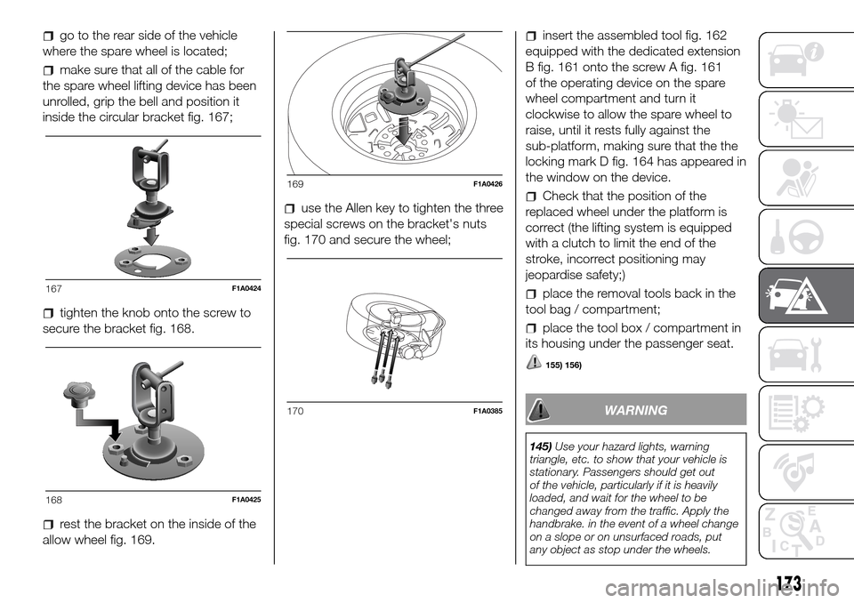
go to the rear side of the vehicle
where the spare wheel is located;
make sure that all of the cable for
the spare wheel lifting device has been
unrolled, grip the bell and position it
inside the circular bracket fig. 167;
tighten the knob onto the screw to
secure the bracket fig. 168.
rest the bracket on the inside of the
allow wheel fig. 169.
use the Allen key to tighten the three
special screws on the bracket's nuts
fig. 170 and secure the wheel;
insert the assembled tool fig. 162
equipped with the dedicated extension
B fig. 161 onto the screw A fig. 161
of the operating device on the spare
wheel compartment and turn it
clockwise to allow the spare wheel to
raise, until it rests fully against the
sub-platform, making sure that the the
locking mark D fig. 164 has appeared in
the window on the device.
Check that the position of the
replaced wheel under the platform is
correct (the lifting system is equipped
with a clutch to limit the end of the
stroke, incorrect positioning may
jeopardise safety;)
place the removal tools back in the
tool bag / compartment;
place the tool box / compartment in
its housing under the passenger seat.
155) 156)
WARNING
145)Use your hazard lights, warning
triangle, etc. to show that your vehicle is
stationary. Passengers should get out
of the vehicle, particularly if it is heavily
loaded, and wait for the wheel to be
changed away from the traffic. Apply the
handbrake. in the event of a wheel change
on a slope or on unsurfaced roads, put
any object as stop under the wheels.
167F1A0424
168F1A0425
169F1A0426
170F1A0385
173
Page 176 of 296

146)The spare wheel supplied (for
versions/markets, where provided) is
specific for your vehicle. Therefore, it must
not be used on other models. Do not
use spare wheels of other models on your
vehicle. The wheel bolts are specific for
your vehicle: do not use them on different
models and do not use bolts from other
models on your car.
147)Repair and refit the standard wheel as
soon as possible. Do not apply grease to
the bolt threads before fitting: they could
come unscrewed.
148)Use the jack only to replace wheels
on the vehicle with which it is supplied
or on other vehicles of the same model.
Never use the jack for other purposes,
such as lifting other vehicle models. Never
use the jack to carry out repairs under
the vehicle. Incorrect positioning of the jack
may cause the lifted vehicle to fall. Do not
use the jack for loads higher than the
one shown on its label.
149)Never tamper with the inflation valve.
Never introduce tools of any kind between
rim and tyre. Check tyre and spare wheel
pressure regularly, referring to the values
shown in the "Technical specifications"
section.
150)No tools other than the crank
provided should be used with the spare
wheel lifting device; it should be operated
by hand only.
151)On versions equipped with self-
levelling air suspension, never introduce the
head or hands in the wheel arch: the
vehicle could raise or lower automatically
depending on possible load or temperature
changes.152)The device should only be operated
by hand, without using any type of tool
other than the crank provided like
pneumatic or electrical screwers.
153)The moving components of the jack
(screws and joints) can also cause injuries:
avoid touching them. If you come into
contact with lubricating grease, clean
yourself thoroughly.
154)At the end of the operation of
raising/locking the spare wheel, after
checking that the wheel is positioned
correctly under the platform (yellow notch
inside the window on the device), extract
the operating wrench. Take care not to turn
the wrench in the wrong direction (as in
fig. 166) to facilitate extracting it, to prevent
the attachment device from being
released and to ensure that the wheel
assembly remains safely fastened.
155)Each time the spare wheel is moved,
check that it is correctly positioned in its
housing under the platform. If it is not
correctly positioned, this could adversely
affect safety.
156)The spare wheel lifting device is
equipped with a clutch safety system for its
own protection; this could activated if an
excessive load is applied on the
maneuvering screw.FIX & GO
AUTOMATIC QUICK
TYRE REPAIR KIT
(for versions/markets, where provided)
The Fix & Go automatic quick tyre
repair kit is located at the front of the
vehicle passenger compartment and
includes fig. 171:
bottle A containing sealer and fitted
with:
– a transparent filler pipe B;
– a black pressure restoring pipe E;
– sticker C bearing the notice “max. 80
km/h”, to be placed in a position visible
to the driver (on the instrument panel)
after fixing the tyre;
171F1A0180
174
IN AN EMERGENCY
Page 177 of 296

information leaflet (see fig. 172), to
be used for prompt and correct use
of the quick tyre repair kit and then to
be given to the personnel that must
handle the tyre treated with the tyre
repair kit;
compressor D complete with
pressure gauge and connectors;
a pair of protective gloves located in
the side compartment of the
compressor;
adaptors for inflating different
elements.
157) 158) 159)
48)
IMPORTANT
INFORMATION:
The sealing fluid of the quick repair kit is
effective at external temperatures of
between –20 °C and +50 °C.
The sealing fluid has an expiry date.
160) 161)
3)
INFLATION PROCEDURE
162) 163) 164) 165) 166)
Pull the handbrake. Unscrew the
tyre valve cap, take out the filler hose A
fig. 173 and tighten the ring nut B
onto the tyre valve;
insert the plug E fig. 175 in the
nearest 12 V power socket and start
the engine. Turn the selector D fig. 174
anticlockwise to the repair position.
Activate the kit by pressing the on/off
switch. Inflate the tyre to the pressure
specified in the "Inflation pressure"
paragraph, in the "Technical Data"
chapter;
For a more accurate reading, it is
advisable to check the pressure on the
pressure gauge F fig. 174 with the
compressor off and without moving the
centre selector from the repair position;
if after 10 minutes it is still
impossible to reach at least 3 bar,
release the transparent filler pipe from
the valve and take out the 12 V plug,
then move the vehicle forwards by
about 10 metres in order to distribute
the sealing fluid inside the tyre evenly,
then repeat the inflation operation;
172F1A0181
173F1A0182
174F1A0183
175
Page 178 of 296

if after this operation it is still
impossible after 10 minutes to reach at
least 3 bar, do not start driving since
the tyre is excessively damaged and the
quick tyre repair kit cannot guarantee
proper hold, contact a Fiat Dealership;
if the tyre reaches the pressure
specified in “Inflation pressure”
paragraph in the "Technical Data"
section, start driving immediately;
after having driven for about 10
minutes, stop and recheck the tyre
pressure; remember to apply the
handbrake;
if a pressure value of at least 3 bar is
detected, restore the correct pressure
prescribed in the paragraph “Inflation
pressure” in “Technical specification”
(with the engine running and the
handbrake engaged), resume driving
and drive with care to nearest Fiat
Dealership.
WARNING
157)Give the booklet to the personnel who
will be handling the tyre treated with the
repair kit.
158)Holes and damage on the tyre side
walls cannot be repaired. Do not use
the quick tyre repair kit if the damage is
due to running with flat tyre.
159)Repairs are not possible in the case of
damage to the wheel rim (bad groove
distortion causing air loss). Do not remove
the foreign body (screws or nails) from
the tyre.
160)Never operate the compressor for
longer than 20 consecutive minutes. Risk
of overheating. Tyres repaired with the
quick tyre repair kit must only be used
temporarily, as the kit is not suitable for a
definitive repair.161)The bottle contains ethylene glycol. It
contains latex that might cause allergic
reactions. It is harmful if swallowed. Eye
irritant. It may cause sensitisation if inhaled
or on contact. Avoid contact with eyes,
skin and clothes. In the event of contact,
wash immediately with plenty of water.
In the event that it is swallowed, do not
induce vomiting. Rinse out your mouth,
drink large quantities of water and seek
immediate medical attention. Keep out of
the reach of children. The product must
not be used by asthmatics. Do not inhale
the vapours during insertion and suction.
Call a doctor immediately if allergic
reactions are noted. Store the bottle in its
proper compartment, away from sources
of heat. The sealing fluid has an expiry
date. Replace the bottle if the sealant has
expired.
162)Put on the protective gloves provided
together with the quick tyre repair kit.
163)Apply the adhesive label in a position
clearly visible by the driver as a reminder
that the tyre has been treated with the
quick repair kit. Drive carefully, particularly
on bends. Do not exceed 80 km/h. Avoid
sudden acceleration or braking.
164)If the pressure falls below 3 bar, do
not drive any further: the Fix & Go
automatic quick tyre repair kit cannot
guarantee suitable sealing because the tyre
is too damaged. Contact a Fiat Dealership.
165)Inform the Dealership that the tyre
has been repaired using the quick tyre
repair kit. Give the booklet to the personnel
who will be handling the tyre treated with
the repair kit.
175F1A0335
176
IN AN EMERGENCY
Page 179 of 296

166)If different tyres from the ones
supplied with the vehicle are used, it may
not be possible to carry out the repair. If
the tyres are replaced, it is advisable to use
those approved by the manufacturer.
Consult a Fiat Dealership.
WARNING
48)In the event of a puncture caused by
foreign bodies, the kit may be used to
repair tyres showing damage on the tread
or shoulder up to max 4 mm diameter.
WARNING
3)Replace the bottle if the sealant has
expired. Dispose of the bottle and the
sealant properly. Have them disposed of in
compliance with national and local
regulations.
JUMP STARTING
If the warning lightremains on
continuously on the instrument panel,
contact the Fiat Dealership immediately.
JUMP STARTING
If the battery is flat, it is possible to start
the engine using an auxiliary battery
with the same capacity or a little higher
than the flat one.
It is advisable to contact a Fiat
Dealership to check/replace the battery.
167)
Proceed as follows to start the vehicle:
lift the flap A fig. 176 to access
the positive battery terminal connection;
connect the positive terminals (+
mark near the terminal) of the two
batteries using a suitable cable;
use a second lead to connect the
negative terminal (–) of the auxiliary
battery to the earth point as shown in
fig. 177;
start the engine;
when the engine has been started,
remove the cables reversing the order
above.
If after a few attempts the engine does
not start, do not persist but contact
the nearest Fiat Dealership.
IMPORTANT Do not directly connect
the negative terminals of the two
batteries: sparks could ignite explosive
gas released from the battery. If the
auxiliary battery is installed on another
vehicle, avoid any metal parts on the
latter and the vehicle with the flat
battery from accidentally coming into
contact.
176F1A0351
177F1A0352
177
Page 180 of 296

BUMP STARTING
Never bump start the engine by
pushing, towing or driving downhill.
This could cause fuel to flow into the
catalytic converter and damage it
beyond repair.
WARNING
167)This starting procedure must be
performed by expert personnel because
incorrect actions could cause electrical
discharge of considerable intensity.
Furthermore, battery fluid is poisonous and
corrosive: avoid contact with skin and
eyes. Keep naked flames and lighted
cigarettes away from the battery and do
not cause sparks.
RECHARGING THE
BATTERY
IMPORTANT The battery recharging
procedure is given as information only.
To carry out this operation contact a
Fiat Dealership.
IMPORTANT After setting the ignition
device to STOP and having closed the
driver side door, wait at least one
minute before disconnecting the
electrical supply from the battery. When
reconnecting the electrical supply to
the battery, make sure that the ignition
device is in the STOP position and
the driver side door is closed.
IMPORTANT Charging should be slow
at a low ampere rating for
approximately 24 hours. Charging for a
longer time may damage the battery.IMPORTANT The cables of the
electrical system must be correctly
reconnected to the battery, i.e. the
positive cable (+) to the positive
terminal and the negative cable (–) to
the negative terminal. The battery
terminals are marked with the positive
(+) and negative (–) symbols, and are
shown on the battery cover. The battery
terminals must also be corrosion-free
and firmly secured to the terminals. If a
"quick-type" battery charger is used
with the battery fitted on the car,
disconnect both battery leads before
connecting it. Do not use a "quick-type"
battery charger to provide the starting
voltage.
168) 169)
VERSIONS WITHOUT
START&STOP SYSTEM
To recharge, proceed as follows:
disconnect the terminal from the
negative battery pole;
connect the charger cables to the
battery terminals, observing the polarity;
turn on the battery charger;
when it is recharged, turn the
charger off before disconnecting it from
the battery;
reconnect the terminal to the
negative battery pole.
178
IN AN EMERGENCY
Page 182 of 296

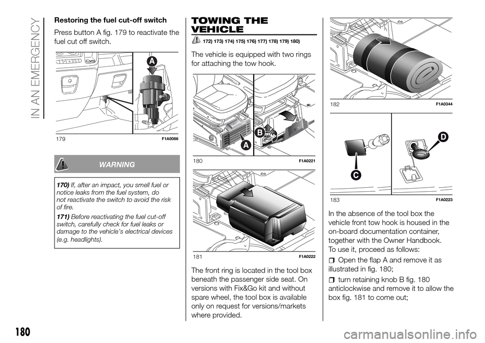
Restoring the fuel cut-off switch
Press button A fig. 179 to reactivate the
fuel cut off switch.
WARNING
170)If, after an impact, you smell fuel or
notice leaks from the fuel system, do
not reactivate the switch to avoid the risk
of fire.
171)Before reactivating the fuel cut-off
switch, carefully check for fuel leaks or
damage to the vehicle's electrical devices
(e.g. headlights).
TOWING THE
VEHICLE
172) 173) 174) 175) 176) 177) 178) 179) 180)
The vehicle is equipped with two rings
for attaching the tow hook.
The front ring is located in the tool box
beneath the passenger side seat. On
versions with Fix&Go kit and without
spare wheel, the tool box is available
only on request for versions/markets
where provided.In the absence of the tool box the
vehicle front tow hook is housed in the
on-board documentation container,
together with the Owner Handbook.
To use it, proceed as follows:
Open the flap A and remove it as
illustrated in fig. 180;
turn retaining knob B fig. 180
anticlockwise and remove it to allow the
box fig. 181 to come out;
179F1A0086
180F1A0221
181F1A0222
182F1A0344
183F1A0223
180
IN AN EMERGENCY