Page 149 of 296
extract
r
r
slightly
\(bayonet
r
clockwise
corr
r
fig.
MAINT
r
C
fr
the
disconnect
fit
outline
the
headlight,
side
r
r
C
DIPPED
HEADLIGHTS
With
T
r
B
fr
the
disconnect
fit
outline
the
headlight,
side
r
r
B
DIRECTION
T
r
A
tur
anticlockwise;
extract
r
r
slightly
\(bayonet
r
clockwise
corr
r
fig.
130F1A0386
131F1A0315
132F1A0316
147
Page 150 of 296

Side
To change the bulbs, proceed as
follows fig. 134:
move the mirror manually to permit
access to the two fixing screws A;
using the Phillips screwdriver
provided, undo the screws and extract
the bulb holder assembly, releasing it
from the teeth;
undo the bulb and replace bulb B,
turning it anticlockwise.FOG LIGHTS
(for versions/markets, where provided)
To replace the front fog light bulbs,
proceed as follows:
steer the wheel completely inwards;
undo the screw A and remove the
flap B fig. 135;
release the clip C fig. 136 and
disconnect the electrical connector D;
turn and remove the bulb holder E;
release the bulb and replace it;
refit the new bulb and carry out the
procedure described previously in
reverse.REAR LIGHT CLUSTERS
The bulbs are arranged inside the light
cluster as follows fig. 137:
A brake/side lights
B side light
C direction indicators
D reverse lights.
E rear fog lights
To replace the bulb, proceed as follows
fig. 138, fig. 139:
open the rear wing door.
133F1A0317
134F1A0195
135F1A0361
136F1A0362
137F1A0318
148
IN AN EMERGENCY
Page 151 of 296
undo the 7 fixing screws A of the
plastic cover;
undo the two fixing screws B;
extract the unit outwards and
disconnect the electrical connector;
unscrew the screws C using the
screwdriver provided and remove the
bulb holder;
remove the bulb D, E, F pushing it
gently and turning it anticlockwise
(“bayonet” locking), then replace it;
remove the bulb G, H pulling outwards;
refit the bulb holder and tighten the
screws C;
reconnect the electrical connector,
correctly reposition the unit on the body
of the vehicle and then tighten the
fixing screws B;
refit the plastic cover fastening it
with the 7 fixing screws A.For truck and chassis cab versions:
Undo the four screws H fig. 140 and
replace the bulbs:
I bulb for rear fog light
L bulb for reversing light
M bulb for side light
N bulb for brake light
O bulb for side light.
138F1A0319139F1A0320
140F1A0200
149
Page 154 of 296

FUSE LOCATION
The vehicle fuses are grouped in three
control units located on the dashboard,
passenger compartment right pillar
and engine compartment.
DASHBOARD FUSEBOX
To access the dashboard fuse box fig.
148, undo the screws A fig. 149 and
remove the cover.ENGINE COMPARTMENT
FUSEBOX – OPTIONAL WIRING
MODULE
To access the fusebox fig. 151 - fig.
152 - fig. 153 - fig. 154, remove its
protective cover fig. 150.
Proceed as follows:
fully tighten the captive screw using
the dedicated Phillips screwdriver
provided;
slowly rotate the screw
anticlockwise until resistance is
encountered (do not overtighten);
slowly release the screw;
opening is indicated by the entire
screw head coming out of its housing;
remove the cover.
To refit the cover proceed as follows:
join the cover with the box correctly;
fully tighten the captive screw using
the dedicated Phillips screwdriver
provided;
slowly rotate the screw clockwise
until resistance is encountered (do not
overtighten);
slowly release the screw;
closure is indicated by the inset of
the entire screw head in its housing.
148F1A0214
149F1A0213
150F1A0334
152
IN AN EMERGENCY
Page 167 of 296

GATEWAY FMS
MODULE
The Gateway FMS Module provides the
interface between the vehicle data
network and the FMS standard.
FMS: The Fleet Management Systems
Interface (FMS) is a standard interface
that allows the vehicle’s digital
electronic control unit signals to be
read. The information in these signals
can be used to facilitate the vehicle’s
personalisation or special outfitting. The
Gateway FMS Module supports the
following FMS Standard versions:
FMS - Standard Interface
description Vers. 02 (available on
http://www.fms-standard.com/
Truck/index.htm)
Bus FMS - Standard Interface
description Vers. 02 (available
onhttp://www.fms-standard.com/Bus/
index.htm)
We advise having the Gateway FMS
Module installed by the Fiat Dealership
or specialist technicians. The fitting
instructions are in the Fitters/Installers
Manual on the HYPERLINK website
"http://www.fiatprofessional-
converters.com"www.fiatprofessional-
converters.com.The following table shows all signals
available to control units interfaced with
the Gateway FMS Module.
165
Page 168 of 296

Message Signal Description
CCVSParking Brake Switch Indicates parking brake engaged
Wheel based speed Indicates vehicle speed
Clutch switch Indicates clutch pedal pressed
Brake switch Indicates brake pedal pressed
Cruise control active Indicates Cruise Control active
EEC2Accelerator pedal position 1 Indicates accelerator pedal position
Engine Percent Load At Current SpeedIndicates percentage ratio between engine torque and
maximum indicated torque at current engine speed
LFC Engine total fuel used Indicates total fuel used during vehicle operation
DD Fuel Level Indicates ratio of fuel volume to total tank volume
EEC1 Engine speed Indicates engine speed
VDHR High resolution total vehicle distance Indicates total vehicle distance travelled
ET1 Engine coolant temperature Indicates temperature of engine coolant
AMB Ambient Air Temperature Indicates temperature outside of vehicle
LFEFuel Rate Indicates quantity of fuel used by engine per time unit
Instantaneous Fuel EconomyIndicates ratio between quantity of fuel used and
current vehicle speed
SERV Service distanceIndicates distance that can be travelled by vehicle
before scheduled servicing
HOURS Total engine hours Indicates total engine operating time
DC1 Position of doors Indicates current door status
AS Alternator Status 1 Indicates current alternator status
166
IN AN EMERGENCY
Page 172 of 296

CHANGING A WHEEL
GENERAL
INSTRUCTIONS
Wheel replacement and correct use of
the jack and spare wheel (for
versions/markets, where provided) call
for some precautions, which are listed
below.
145) 146) 147) 148) 149)
Please note that:
the jack weight is 4.5 kg;
the jack requires no adjustment;
the jack cannot be repaired: in the
event of a fault it must be replaced
by another original one;
no tool other than its cranking
device may be fitted on the jack.
150)
To change a wheel, proceed as
follows:
stop the vehicle in a position that is
not dangerous for oncoming traffic
where you can change the wheel safely.
The ground must be flat and sufficiently
compact;
switch off the engine and pull the
handbrake;
engage first gear or reverse;
put on the reflective safety jacket
(compulsory by law in certain countries)
before getting out of the vehicle;
indicate that the vehicle has broken
down using the devices required by
the law in the current country (e.g.
warning triangle, hazard lights, etc.);
In the event of a wheel change on a
slope or on unsurfaced roads, put
any object as stop under the wheels;
take the tool bag from under the
passenger seat (see "Compartment
under the front passenger side seat" in
the "Internal equipment" chapter in
"Knowing the vehicle").
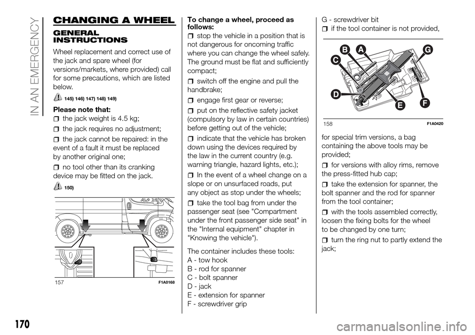
The container includes these tools:
A - tow hook
B - rod for spanner
C - bolt spanner
D - jack
E - extension for spanner
F - screwdriver gripG - screwdriver bit
if the tool container is not provided,
for special trim versions, a bag
containing the above tools may be
provided;
for versions with alloy rims, remove
the press-fitted hub cap;
take the extension for spanner, the
bolt spanner and the rod for spanner
from the tool container;
with the tools assembled correctly,
loosen the fixing bolts for the wheel
to be changed by one turn;
turn the ring nut to partly extend the
jack;
157F1A0168
158F1A0420
170
IN AN EMERGENCY
Page 173 of 296

position the jack at the lifting support
nearest the wheel to be replaced, at
the points shown in fig. 157. For short
wheelbase versions with a retractable
footboard, the jack must be position at
the lifting point shown in fig. 159,
turned by 45° so that it does
not interfere with the retractable
platform;
warn all bystanders that the vehicle
is about to be lifted. They must stay
clear and not touch the vehicle until it is
back on the ground.
for versions equipped with
self-levelling pneumatic suspension,
before using the jack to raise the
vehicle, press the buttons A and B fig.
160 simultaneously for at least 5
seconds. The operating mode for
raising the vehicle is activated: the
LEDs on the buttons come on
constantly. To exit this mode, press
buttons A and B simultaneously for
another 5 seconds; both LEDs on the
buttons will go out and full system
operation will be restored. This mode
deactivates automatically when the
speed of approx. 5 km/h is exceeded.
151)
lift the vehicle.
After lifting the vehicle:
for all versions, access the rear right
wheel arch, operate the screw A fig.
161 on the spare wheel retaining
device, using the supplied wrench
assembled correctly with the dedicated
extension B fig. 161.
turn the tool anticlockwise fig. 162
to allow the spare wheel to descend;
continue turning anticlockwise until
the stop point, indicated by the
stiffening of the manoeuvre or a click
from the clutch present in the device;
152) 153)
after unwinding the whole cable of
the spare wheel lifting device, remove
the wheel from the vehicle;
undo the retaining knob D fig. 163
and free the wheel by sliding out the
support E.
159F1A0169
160F1A0170
161F1A0171
171