2016 FIAT DOBLO PANORAMA clock
[x] Cancel search: clockPage 85 of 323
– press theMENUbutton briefly to
return to the menu screen or hold the
button down to return to the standard
screen without storing.
Set Time (Setting the
clock)
This function enables the clock to be
set through two submenus: "Time" and
"Format".
To carry out the adjustment, proceed as
follows:
– briefly pressMENU
; the display
will show the two sub-menus “Time”
and “Mode”;
– press the
orbutton to switch
between the two submenus;
– select the required option and then
pressMENU
briefly;
– if selecting the “Time” submenu,
briefly pressMENU
, the “hours”
will flash on the display;
– press the
orbutton to make the
adjustment;
– briefly press theMENU
button;
the “minutes” will flash on the display;
– press the
orbutton for setting.NOTE The setting will increase or
decrease by one unit each time the
orbutton is pressed. Hold down
the button to increase/decrease the
setting rapidly and automatically.
Complete the adjustment with single
presses of the button when you
approach the desired value.
– when you select “Mode”, pressing the
MENU
button makes the mode
flash on the display;
– press the
orbutton to select
"24h" or "12h".
When you have made the required
settings, press theMENU
button
briefly to go back to the submenu
screen or hold the button down to go
back to the main menu screen without
saving.
– hold theMENU
button down
again to return to the standard screen
or to the main menu according to
where you are in the menu.
Set Date (Setting the
date)
Using this function you can update the
date (day - month - year).
Proceed as follows to update:
– briefly press theMENU
button:
“year” will flash on the display;– press the
orbutton to make the
adjustment;
– briefly press theMENU
button:
"month" will flash on the display;
– press the
orbutton to make the
adjustment;
– briefly press theMENU
button:
“day” will flash on the display;
– press the
orbutton for setting.
NOTE The setting will increase or
decrease by one unit each time the
orbutton is pressed. Hold down
the button to increase/decrease the
setting rapidly and automatically.
Complete the adjustment with single
presses of the button when you
approach the desired value.
– press theMENU
button briefly to
return to the menu screen or hold the
button down to return to the standard
screen without storing.
See radio (audio
information repetition)
(for versions/markets, where provided)
With this function the display shows
information about the radio.
– Radio: selected radio station
frequency or RDS message, automatic
tuning activation or AutoSTore;
– Audio CD, MP3 CDs: track number;
81
Page 150 of 323

REFUELLING THE
VEHICLE
PETROL ENGINES
Only use unleaded petrol, with an
octane number (R.O.N.) not lower than
95.
IMPORTANT An inefficient catalytic
converter leads to harmful exhaust
emissions, thus contributing to air
pollution.
IMPORTANT Never use leaded petrol,
even in small amounts or in an
emergency, as this would damage the
catalytic converter beyond repair.
DIESEL ENGINES
Operation at low
temperatures
If the outside temperature is very low,
the diesel thickens due to the formation
of paraffin clots with consequent
defective operation of the fuel supply
system.In order to avoid these problems,
different types of diesel are distributed
according to the season: summer type,
winter type and arctic type (cold/
mountain areas). If refuelling with diesel
fuel whose specifications are not
suitable for the current temperature, it is
advisable to mix TUTELA DIESEL ART
additive in the proportions shown on
the container. Pour the additive into the
tank before the diesel fuel.
When using or parking the vehicle for a
long time in the mountains or cold
areas, it is advisable to refuel using
locally available diesel fuel.
In this case, it is also advisable to keep
the tank over 50% full.
22)
FILLING THE TANK
To fill the tank completely, top up twice
after the first click of the fuel supply
gun. Further top ups could cause faults
in the fuel supply system.
FUEL TANK PLUG
Opening
1) Open flap A fig. 153, pulling it
outwards, hold cap B still, insert the
ignition key in the lock and turn it
anticlockwise.2) Turn the cap anticlockwise and
remove it. The cap has a device C that
attaches it to the flap so it cannot be
lost. When refilling, attach the plug
to the flap, as shown.
Closing
1) Fit the cap (complete with key) and
turn it clockwise until it clicks once
or more.
2) Turn the key clockwise and extract it,
then close the flap.
The sealing may cause a slight pressure
increase in the tank. A little breathing
off, while slackening the plug is
absolutely normal.
153F0V0086
146
STARTING AND DRIVING
Page 157 of 323

TYPES OF BULBS
Various types of bulbs are fitted to your
vehicle fig. 155:
AGlass bulbs: they are press-fitted.
Pull to extract.
BBayonet type bulbs: to remove from
its holder, press the bulb, turn it
anticlockwise, then remove.
CTubular bulbs: release them from their
contacts to remove.
DHalogen bulbs: to remove the bulb,
release the clip holding the bulb in
place.
EHalogen bulbs: to remove the bulb,
release the clip holding the bulb in
place.
WARNING
103) Modifications or repairs to the
electric system that are not
carried out properly or do not take
the system technical
specifications into account can
cause malfunctions leading to the
risk of fire.
104) Halogen bulbs contain
pressurised gas; in the case of
breakage they may burst.
IMPORTANT
24) Halogen bulbs must be handled
by holding the metallic part only.
If the transparent bulb is touched
with the fingers, its lighting
intensity is reduced and life of the
bulb may be compromised. In
the case of accidental contact,
rub the lamp with a cloth and
alcohol and leave to dry.
25) Where possible, it is advisable to
have bulbs changed at a Fiat
Dealership. Proper operation and
direction of the external lights
are essential for driving in safety
and comply with law.
155F0V0027
153
Page 159 of 323
REPLACING AN
EXTERIOR BULB
For the type of bulb and relevant power
rating, see “Changing a bulb”.
FRONT LIGHT CLUSTERS
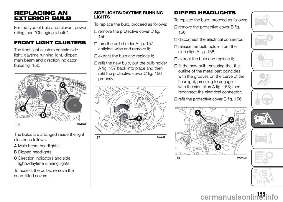
The front light clusters contain side
light, daytime running light, dipped,
main beam and direction indicator
bulbs fig. 156.
The bulbs are arranged inside the light
cluster as follows:
AMain beam headlights:
BDipped headlights;
CDirection indicators and side
lights/daytime running lights
To access the bulbs, remove the
snap-fitted covers.SIDE LIGHTS/DAYTIME RUNNING
LIGHTS
To replace the bulb, proceed as follows:
❒remove the protective cover C fig.
156;
❒turn the bulb holder A fig. 157
anticlockwise and remove it;
❒extract the bulb and replace it;
❒refit the new bulb, put the bulb holder
A fig. 157 back into place and then
refit the protective cover C fig. 156
properly.DIPPED HEADLIGHTS
To replace the bulb, proceed as follows:
❒remove the protective cover B fig.
156;
❒disconnect the electrical connector;
❒release the bulb holder from the
side clips A fig. 158;
❒extract the bulb and replace it;
❒fit the new bulb, ensuring that the
outline of the metal part coincides
with the grooves on the curve of the
headlight, pressing to engage it
with the side clips A fig. 158; then
reconnect the electrical connector;
❒refit the protective cover B fig. 156.
156F0V0520
157F0V0521
158F0V0522
155
Page 160 of 323
DIRECTION INDICATORS
Front
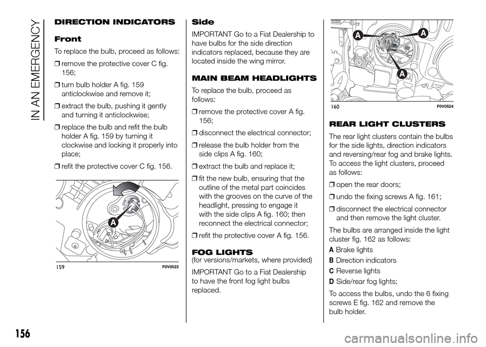
To replace the bulb, proceed as follows:
❒remove the protective cover C fig.
156;
❒turn bulb holder A fig. 159
anticlockwise and remove it;
❒extract the bulb, pushing it gently
and turning it anticlockwise;
❒replace the bulb and refit the bulb
holder A fig. 159 by turning it
clockwise and locking it properly into
place;
❒refit the protective cover C fig. 156.Side
IMPORTANT Go to a Fiat Dealership to
have bulbs for the side direction
indicators replaced, because they are
located inside the wing mirror.
MAIN BEAM HEADLIGHTS
To replace the bulb, proceed as
follows:
❒remove the protective cover A fig.
156;
❒disconnect the electrical connector;
❒release the bulb holder from the
side clips A fig. 160;
❒extract the bulb and replace it;
❒fit the new bulb, ensuring that the
outline of the metal part coincides
with the grooves on the curve of the
headlight, pressing to engage it
with the side clips A fig. 160; then
reconnect the electrical connector;
❒refit the protective cover A fig. 156.
FOG LIGHTS
(for versions/markets, where provided)
IMPORTANT Go to a Fiat Dealership
to have the front fog light bulbs
replaced.REAR LIGHT CLUSTERS
The rear light clusters contain the bulbs
for the side lights, direction indicators
and reversing/rear fog and brake lights.
To access the light clusters, proceed
as follows:
❒open the rear doors;
❒undo the fixing screws A fig. 161;
❒disconnect the electrical connector
and then remove the light cluster.
The bulbs are arranged inside the light
cluster fig. 162 as follows:
ABrake lights
BDirection indicators
CReverse lights
DSide/rear fog lights;
To access the bulbs, undo the 6 fixing
screws E fig. 162 and remove the
bulb holder.
159F0V0523
160F0V0524
156
IN AN EMERGENCY
Page 161 of 323
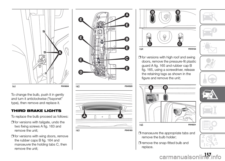
To change the bulb, push it in gently
and turn it anticlockwise (“bayonet”
type), then remove and replace it.
THIRD BRAKE LIGHTS
To replace the bulb proceed as follows:
❒for versions with tailgate, undo the
two fixing screws A fig. 163 and
remove the unit;
❒for versions with wing doors, remove
the rubber caps B fig. 164 and
manoeuvre the holding tabs C, then
remove the unit;❒for versions with high roof and swing
doors, remove the pressure-fit plastic
guard A fig. 165 and rubber cap B
fig. 165, using a screwdriver, release
the retaining tags as shown in the
figure and remove the unit;
❒manoeuvre the appropriate tabs and
remove the bulb holder;
❒remove the snap-fitted bulb and
replace.
161F0V0034162F0V0525
163F0V0163
164F0V0164
165F0V0231
157
Page 162 of 323
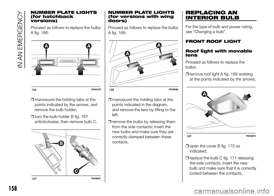
NUMBER PLATE LIGHTS
(for hatchback
versions)
Proceed as follows to replace the bulbs
A fig. 166:
❒manoeuvre the holding tabs at the
points indicated by the arrows, and
remove the bulb holder;
❒turn the bulb holder B fig. 167
anticlockwise, then remove bulb C.NUMBER PLATE LIGHTS
(for versions with wing
doors)
Proceed as follows to replace the bulbs
A fig. 168:
❒manoeuvre the holding tabs at the
points indicated in the diagram,
and remove the lens by lifting to the
left;
❒remove the bulbs by releasing them
from the side contacts; insert the
new bulbs and make sure they are
correctly clamped between these
contacts.REPLACING AN
INTERIOR BULB
For the type of bulb and power rating,
see "Changing a bulb".
FRONT ROOF LIGHT
Roof light with movable
lens
Proceed as follows to replace the
bulbs:
❒remove roof light A fig. 169 working
at the points indicated by the arrows;
❒open the cover B fig. 170 as
indicated;
❒replace the bulb C fig. 171 releasing
the side contacts, insert the new
bulb and make sure that it is correctly
locked between the contacts;
166F0V0179
167F0V0037
168F0V0036
169F0V0070
158
IN AN EMERGENCY
Page 176 of 323

❒if after 5 minutes it is still impossible
to reach at least 1.5 bar, disengage
the compressor from the valve and
power socket, then move the vehicle
forwards by approx. 10 metres in
order to distribute the sealant inside
the tyre evenly, then repeat the
inflation operation;
❒if after this operation it is still
impossible after 5 minutes to reach at
least 1.8 bar, do not start driving
since the tyre is excessively damaged
and the quick tyre repair kit cannot
guarantee proper hold, contact a Fiat
Dealership;
❒if reaching the tyre pressure specified
in paragraph “Inflation pressure” in
chapter “Technical Data”, start driving
immediately;
118) 119) 120)
❒after having driven for about 10
minutes, stop and recheck the tyre
pressure fig. 205; remember to apply
the handbrake;
❒if at least 1.8 bar pressure is read,
restore correct pressure (with engine
running and handbrake on) and
restart;
❒drive with the utmost care to the
nearest Fiat Dealership.FOR CHECKING AND
RESTORING PRESSURE
ONLY
The compressor can also be used
solely for restoring pressure. Release
the quick coupling and connect directly
to the tyre valve fig. 206; in this way,
the bottle will not be connected to the
compressor and no sealing fluid will
be injected.BOTTLE REPLACEMENT
PROCEDURE
To replace the bottle, proceed as
follows:
❒disconnect coupling B fig. 207;
❒turn the bottle to be replaced
anticlockwise and raise it;
❒fit the new bottle and turn it
clockwise;
❒connect coupling B to the cylinder
and fit transparent pipe A in the
specific compartment.
205F0V0098
206F0V0099
207F0V0100
172
IN AN EMERGENCY