2016 FIAT DOBLO PANORAMA change wheel
[x] Cancel search: change wheelPage 9 of 323

VEHICLE MODIFICATIONS / ALTERATIONS
IMPORTANT
Any change or alteration of the vehicle might seriously affect its safety and road holding, thus causing accidents, in which the
occupants could even be fatally injured.
ACCESSORIES PURCHASED BY THE OWNER
If after buying the vehicle, you decide to install electrical accessories that require a permanent electrical supply (e.g. radio,
satellite anti-theft system, etc.) or accessories that in any case burden the electrical supply, contact a Fiat Dealership, whose
personnel will check whether the vehicles's electrical system is able to withstand the load required, or whether it needs to
be integrated with a more powerful battery.
IMPORTANT Take care when fitting additional spoilers, alloy wheels or non-standard wheel hubs: they could reduce the
ventilation of the brakes and affect efficiency under sharp, repeated braking or on long descents. Make sure that nothing
obstructs the pedal stroke (mats, etc.).
INSTALLING ELECTRICAL/ELECTRONIC DEVICES
Electrical and electronic devices installed after buying the vehicle and available as after-sales must carry the following label
.
Fiat authorises the installation of transceivers provided that installation is carried out at a specialised centre, in a workmanlike
fashion and in compliance with manufacturer's specifications.
IMPORTANT Traffic authorities may not allow the vehicle on the road if devices are fitted that involve modifications to the
features of the vehicle. This may also cause lapse of the warranty in relation to faults caused by the change or either directly or
indirectly related to it.
Fiat shall not be liable for damage caused by the installation of accessories either not supplied or recommended by Fiat and/or
not installed in compliance with the provided instructions.
RADIO TRANSMITTERS AND MOBILE PHONES
Radio transmitters (car phones, CB radios etc.) cannot be used inside the vehicle unless a separate aerial is mounted
externally.
Transmission and reception of these devices may be affected by the shielding effect of the vehicle body. As far as the use of
EC-approved mobile phones is concerned (GSM, GPRS, UMTS, LTE), follow the usage instructions provided by the mobile
phone Manufacturer.
Page 39 of 323

Lane change function
If you wish to signal a lane change,
place the left stalk in the unstable
position for less than half a second. The
direction indicator on the side selected
will flash five times and then switch
off automatically.
"FOLLOW ME HOME"
DEVICE
This device allows the illumination of the
space in front of the vehicle for a preset
time.
Activation
With the ignition key in the STOP
position or extracted, pull the stalk
towards the steering wheel and move it
within 2 minutes of the engine switching
off.Each time the stalk is moved, the lights
stay on for an extra 30 seconds up to
a maximum of 210 seconds; then
the lights are switched off automatically.
The warning light
on the
instrument panel will light up and the
corresponding message will appear in
the display (see “Warning lights and
messages” section) for as long as the
function is activated.
The warning light comes on when the
stalk is operated and stays on until
the function is automatically
deactivated.
Each movement of the stalk only
increases the amount of time the lights
stay on.
Deactivation
Keep the stalk pulled towards the
steering wheel for more than 2
seconds.WARNING
27) The daytime running lights are
an alternative to dipped
headlights for driving during the
daytime. They are compliant in
countries where is it obligatory to
have lights on during the day
and permitted in those where it is
not obligatory. Daytime running
lights cannot replace dipped
headlights when driving at night
or through tunnels. The use of
daytime running lights is
governed by the highway code of
the country in which you are
driving. Comply with the
prescriptions.
59F0V0516
35
Page 112 of 323

ESC (Electronic
Stability Control)
SYSTEM
(for versions/markets, where provided)
IN BRIEF
This is an electronic system that
controls vehicle stability in the event
of tyre grip loss, helping to maintain
directional control.
The ESC system is therefore
particularly useful when grip
conditions of road surfaces change.
The MSR system (adjustment of
the engine braking torque during gear
changes) and the HBA system
(automatic increase in the braking
pressure during emergency braking)
are present with ESC, ASR and
Hill Holder systems (for
versions/markets where provided).
SYSTEM INTERVENTION
This is signalled by the flashing of the
warning light in the instrument panel,
to inform the driver that the vehicle is
in critical stability and grip conditions.SYSTEM ACTIVATION
The ESC system is automatically
activated when the vehicle is started.
FAULT INDICATIONS
In the event of a fault, the ESC will be
automatically switched off and the
warning light will come on
permanently on the instrument panel
along with a message on the
multifunction display (for versions/
markets where provided) (see "Warning
lights and messages" section). The
LED on the ASR OFF button will also
light up. Contact a Fiat Dealership
as soon as possible.
58)
HILL HOLDER SYSTEM
This system is an integral part of the
ESC system and facilitates starting on
slopes. It is automatically activated
in the following conditions:
❒uphill: vehicle stationary on a road
with a gradient higher than 5%,
engine running, brake pressed and
gearbox in neutral or gear (other than
reverse) engaged;
❒downhill: vehicle stationary on a road
with a gradient higher than 5%,
engine running, brake pressed and
reverse gear engaged.When setting off, the ESC system
control unit maintains the braking
pressure at the wheels until the torque
necessary for starting is reached, or
in any case for a maximum of 1.75
seconds, allowing your right foot to be
moved easily from the brake pedal to
the accelerator.
If the vehicle has not departed after
1.75 seconds, the system will
deactivate automatically by gradually
releasing the brake force.
During this release stage, the typical
brake disengagement noise indicating
that the vehicle is going to move
imminently will be heard.
Fault indications
Any system fault is indicated by the
turning on of the
warning light on
the instrument panel with digital display
and the
warning light on the
instrument panel with multifunction
display (for versions/markets where
provided) (see section “Warning lights
and messages”).
IMPORTANT The Hill Holder system is
not a parking brake, therefore do not
leave the vehicle without activating the
handbrake, switching off the engine
and engaging first gear.
59)
108
SAFETY
Page 142 of 323

TPMS (Tyre
Pressure
Monitoring System)
(for versions/markets, where provided)
86) 87) 88) 89) 90) 91) 92) 93) 94)
DESCRIPTION
The tyre pressure monitoring system
(TPMS) warns the driver of low tyre
pressure on the basis of the cold
inflation pressure prescribed for the
vehicle.
Changes in outside temperature may
cause tyre pressure to vary. This means
that a decrease in the outside
temperature corresponds to a decrease
in the tyre pressure.
Tyre pressure must always be adjusted
according to the cold inflation pressure.
Cold tyre inflation pressure is the tyre
pressure after letting the vehicle stand
for at least three hours or a travel
shorter than 1.6 km after an interval of
three hours.
The cold tyre inflation pressure must
not exceed the maximum inflation
pressure value printed on the side of
the tyre.The tyre pressure also increases while
driving the vehicle: this is a normal
condition and does not require any
adjustment of the pressure.
NOTE
❒The TPMS does not replace the
normal tyre maintenance service and
does not indicate any fault in a tyre.
❒Therefore, the TPMS should not be
used as pressure switch while
adjusting the tyre inflation pressure.
❒Driving with insufficient tyre pressure
causes their overheating and can
result in tyre failure. The low inflation
pressure reduces fuel efficiency
and tyre tread life and may also affect
handling and braking performance
of the vehicle.
❒The TPMS does not replace the
correct tyre maintenance. It is up to
the driver to maintain the correct tyre
pressure level measuring it with a
suitable pressure switch. This is
necessary even if the decrease in the
inflation pressure value does not
cause the tyre pressure control
warning light to switch on.❒The TPMS warns the driver of any
condition of insufficient tyre pressure
If this drops below the insufficient
pressure limit for any reason including
low temperature and normal
pressure loss of the tyre.
❒The seasonal temperature changes
affect tyre pressure.
The TPMS uses wireless devices with
electronic sensors mounted on the
wheel rims to constantly monitor the
value of tyre pressure. The sensors
mounted on each wheel as part of the
valve stem transmit various information
of the tyres to the receiver module, in
order to calculate the pressure.
IMPORTANT Monitoring and
maintaining the correct pressure in all
four tyres are particularly important.
Tyre pressure
monitoring system low
pressure warning
The system warns the driver if one or
more tyres are flat by switching on
the warning light
on the instrument
panel (together with a warning message
and an acoustic signal).
138
STARTING AND DRIVING
Page 154 of 323

All four tyres should be the same (brand
and track) to ensure greater safety
when driving and braking as well as a
good manoeuvrability.
Remember that you should not change
the rotation direction of the tyres.
101)
WARNING
101) The max. speed for snow tyres
with “Q” marking is 160 km/h. The
Road Traffic Code speed limits
must however be always strictly
observed.
SNOW CHAINS
The use of snow chains should be in
compliance with local regulations.
The snow chains may be applied only
onto the front wheel (drive wheels).
Check the tension of the snow chains
after the first few metres have been
driven.
102)
WARNING
102) Keep your speed down when
snow chains are fitted; do not
exceed 50 km/h. Avoid potholes,
steps and pavements and avoid
driving for long distances on
roads not covered with snow to
prevent damaging the vehicle and
the roadbed.
150
STARTING AND DRIVING
Page 170 of 323

CHANGING A WHEEL
The vehicle is originally equipped with
the Fix&Go automatic quick tyre repair
kit (see instructions in the next section).
As an alternative, the vehicle may
have a normal-sized spare wheel.
Wheel changing and correct use of the
jack and spare wheel call for some
precautions, as listed below.
108) 109) 110) 111)
Note for one-way tyres
One-way tyres have a few arrows
on the side indicating the rotation
direction. If a wheel is changed (when
punctured, for example) the direction of
the arrows on the spare wheel tyre
may not coincide with the rotation
direction of the wheel to be replaced.
In these conditions, too, the tyre still
maintains its safety features.
Anyway, it is recommended to have the
wheel repaired and refitted as soon as
possible, as the best performance is
achieved when the rotation direction of
all tyres coincides with the one
indicated by the arrows.
Please note that:
❒the jack weight is 4 kg;
❒the jack requires no adjustment;❒the jack cannot be repaired and in
the event of a fault it must be
replaced by another original one;
❒no tool other than its cranking device
may be fitted on the jack.
To change a wheel, proceed as follows:
❒stop the vehicle in a position that is
not dangerous for oncoming traffic
where you can change the wheel
safely. The ground should be flat
if possible, and sufficiently firm;
❒stop the engine and pull the
handbrake;
❒engage first gear or reverse;
❒wear the reflective safety jacket
(compulsory by law in certain
countries) before getting out of the
vehicle;
❒indicate that the vehicle has broken
down using the devices required by
the law in the current country (e.g.
warning triangle, hazard lights, etc.);
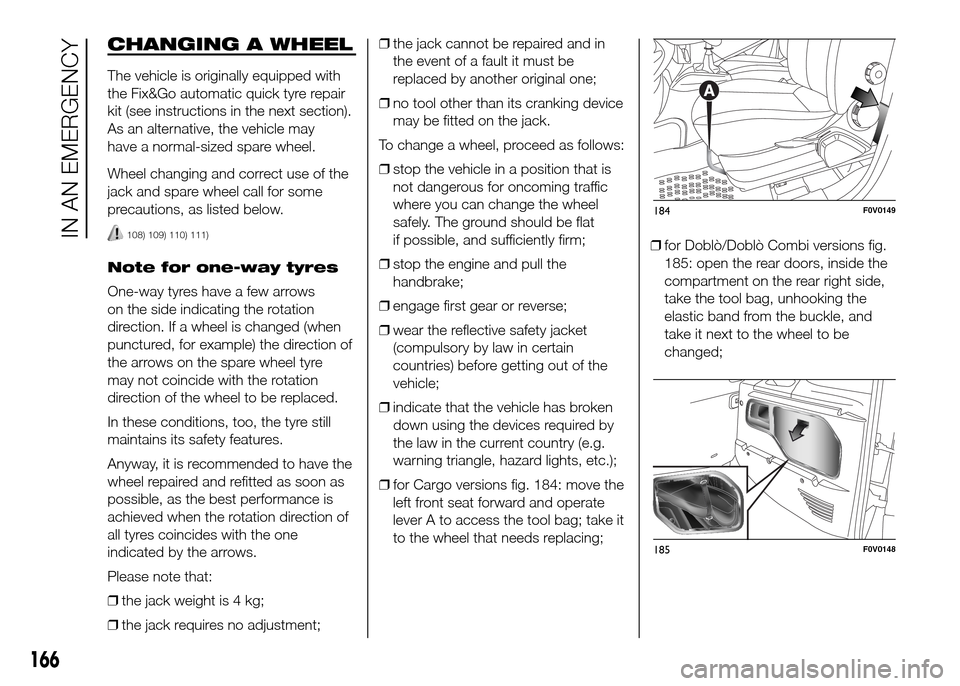
❒for Cargo versions fig. 184: move the
left front seat forward and operate
lever A to access the tool bag; take it
to the wheel that needs replacing;❒for Doblò/Doblò Combi versions fig.
185: open the rear doors, inside the
compartment on the rear right side,
take the tool bag, unhooking the
elastic band from the buckle, and
take it next to the wheel to be
changed;
184F0V0149
185F0V0148
166
IN AN EMERGENCY
Page 171 of 323

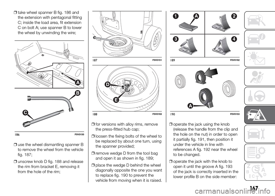
❒take wheel spanner B fig. 186 and
the extension with pentagonal fitting
C; inside the load area, fit extension
C on bolt A; use spanner B to lower
the wheel by unwinding the wire;
❒use the wheel dismantling spanner B
to remove the wheel from the vehicle
fig. 187;
❒unscrew knob D fig. 188 and release
the rim from bracket E, removing it
from the hole of the rim;❒for versions with alloy rims, remove
the press-fitted hub cap;
❒loosen the fixing bolts of the wheel to
be replaced by about one turn, using
the spanner provided;
❒remove wedge D from the tool bag
and open it as shown in fig. 189;
❒place the wedge D behind the wheel
diagonally opposite the one you want
to replace fig. 190 to prevent the
vehicle from moving when it is raised.❒operate the jack using the knob
(release the handle from the clip and
the hole on the nut) in order to open
it partially fig. 191, then position it
under the vehicle in line with
references A fig. 192 near the wheel
to be changed.
❒operate the jack with the knob to
open it until the groove A fig. 193
of the jack is correctly inserted in the
lower profile B on the side member:
B
C
186F0V0150
187F0V0151
188F0V0193
189F0V0192
190F0V0153
167
Page 174 of 323

WARNING
108) The spare wheel (where
provided) is specifically for your
vehicle. Therefore, it must not be
used on other models. Do not
use spare wheels of other models
on your vehicle. The spare wheel
must be used only in an
emergency. Use of the spare
wheel must kept to the minimum
necessary.
109) Use your hazard lights, warning
triangle, etc. to show that your
vehicle is stationary according to
the regulations in force.
Passengers should get out of the
vehicle, particularly if it is heavily
loaded, and wait for the wheel
to be changed away from the
traffic. If you are on a slope or
uneven surface, place wedges or
other suitable objects under the
wheels to secure the vehicle.
Have the wheel repaired and
refitted as soon as possible. Do
not apply grease to the bolt
threads before assembly: they
might spontaneously unscrew.110) Use the jack only to replace
wheels on the vehicle with which
it is supplied or on other vehicles
of the same model. Never use
the jack for other purposes, such
as lifting other models. Never
use the jack to carry out repairs
under the vehicle. Incorrect
positioning of the jack may cause
the lifted vehicle to fall. Do not
use the jack for loads higher than
those shown on the label.
111) Incorrect hub cap assembly
may cause it to come off when the
vehicle is moving. Never tamper
with the inflation valve. Never
introduce tools of any kind
between rim and tyre. Check tyre
and spare wheel pressures
regularly, referring to the values
shown in the "Technical
specifications" section.
FIX&GO automatic
QUICK TYRE REPAIR
KIT
The quick repair kit Fix&Go automatic is
contained in a suitable bag inside the
compartment on the right rear side
or, for Cargo versions, under the
passenger seat (for versions with fixed
or movable seat), or in the glove
compartment (for versions with folding
seat).
The quick tyre repair kit contains fig.
200:
❒bottle A containing sealer and fitted
with: – filler tube B
– sticker C bearing the notice “max. 80
km/h”, to be placed in a position visible
to the driver (on the instrument panel)
after fixing the tyre
200F0V0093
170
IN AN EMERGENCY