Page 85 of 587

The BSM detection zone covers approximately one lane
width on both sides of the vehicle, 10 ft (3 m). The zone
length starts at the outside mirror and extends approxi-
mately 20 ft (6 m) beyond the rear bumper of the vehicle.
The BSM system monitors the detection zones on both
sides of the vehicle when the vehicle speed reaches
approximately 6 mph (10 km/h) or higher and will alert
the driver of vehicles in these areas.
NOTE:
•The BSM system does NOT alert the driver about
rapidly approaching vehicles that are outside the de-
tection zones.
• If a trailer is connected to the vehicle, it is necessary to
deactivate BSM system manually by settings menu to
avoid a miss-detection. Refer to “Uconnect Settings” in
“Multimedia” for further information. The area on the rear fascia where the radar sensors are
located must remain free of snow, ice, and dirt/road
contamination so that the BSM system can function
properly. Do not block the radar sensors located on the
rear fascia with foreign objects (bumper stickers, bicycle
racks, etc.).
Rear Sensor Locations
4
GETTING TO KNOW YOUR VEHICLE 83
Page 330 of 587

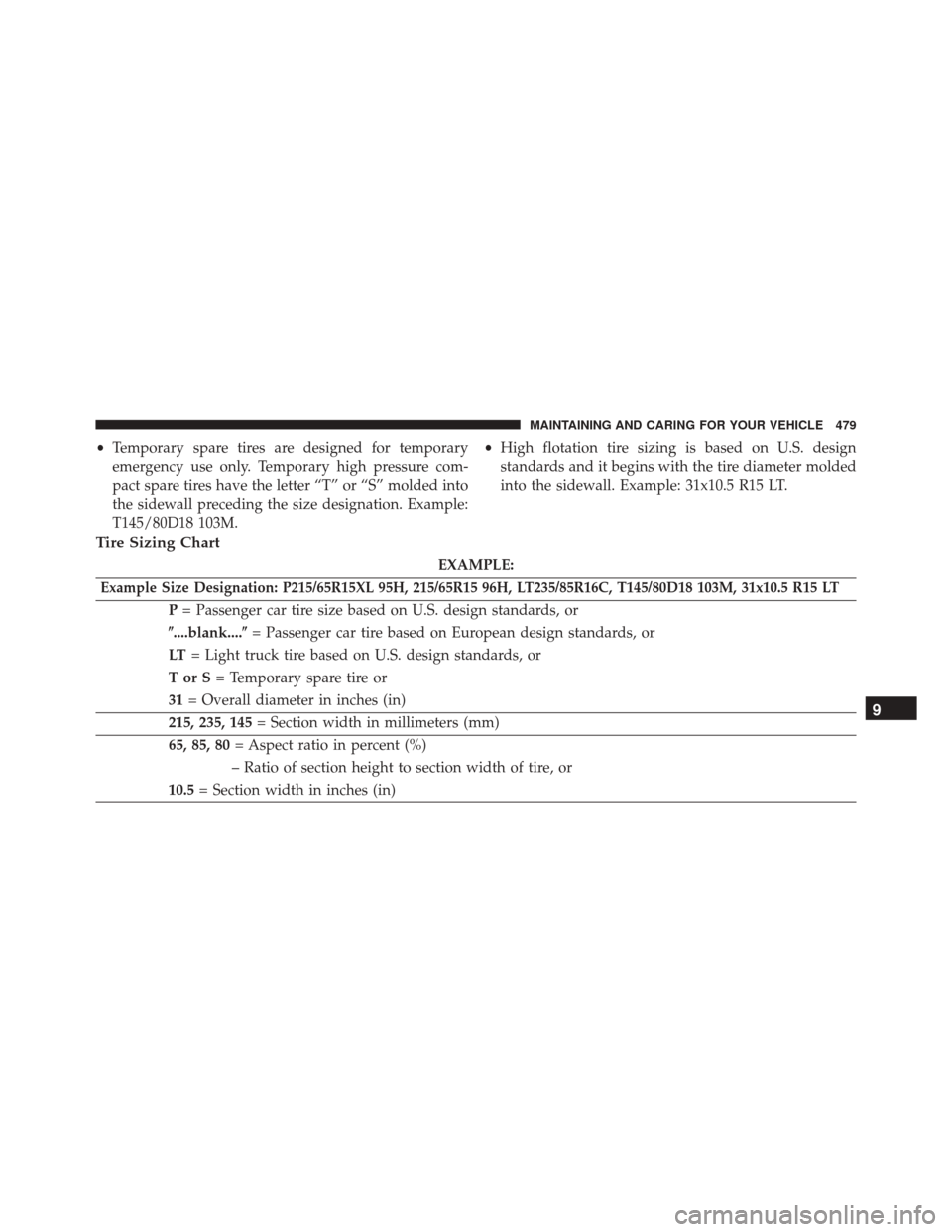
When the vehicle is shifted out of REVERSE (with camera
delay turned OFF), the rear camera mode is exited and
the navigation or audio screen appears again.
When the vehicle is shifted out of REVERSE (with camera
delay turned ON), the camera image will continue to be
displayed for up to 10 seconds after shifting out ofREVERSE unless the vehicle speed exceeds 8 mph
(13 km/h), the vehicle is shifted into PARK or the ignition
is switched to the STOP/OFF position.
A touchscreen button to disable the camera is available
when the vehicle is not in REVERSE. Display of the
camera image after shifting out of REVERSE can be
disabled via Uconnect Settings.
When enabled, active guide lines are overlaid on the
image to illustrate the width of the vehicle and its
projected backup path based on the steering wheel
position.
When enabled, fixed guide lines are overlaid on the
image to illustrate the width of the vehicle.
Different colored zones indicate the distance to the rear of
the vehicle.
Parking Camera
328 STARTING AND OPERATING
Page 480 of 587
TIRE SAFETY INFORMATION
Tire MarkingsNOTE:
•P (Passenger) — Metric tire sizing is based on U.S.
design standards. P-Metric tires have the letter “P”
molded into the sidewall preceding the size designa-
tion. Example: P215/65R15 95H.
• European — Metric tire sizing is based on European
design standards. Tires designed to this standard have
the tire size molded into the sidewall beginning with
the section width. The letter �P�is absent from this tire
size designation. Example: 215/65R15 96H.
• LT (Light Truck) — Metric tire sizing is based on U.S.
design standards. The size designation for LT-Metric
tires is the same as for P-Metric tires except for the
letters “LT” that are molded into the sidewall preced-
ing the size designation. Example: LT235/85R16.
1 — U.S. DOT Safety Standards
Code (TIN) 4 — Maximum Load
2 — Size Designation 5 — Maximum Pressure
3 — Service Description 6 — Treadwear, Traction and Temperature Grades
478 MAINTAINING AND CARING FOR YOUR VEHICLE
Page 481 of 587

•Temporary spare tires are designed for temporary
emergency use only. Temporary high pressure com-
pact spare tires have the letter “T” or “S” molded into
the sidewall preceding the size designation. Example:
T145/80D18 103M. •
High flotation tire sizing is based on U.S. design
standards and it begins with the tire diameter molded
into the sidewall. Example: 31x10.5 R15 LT.
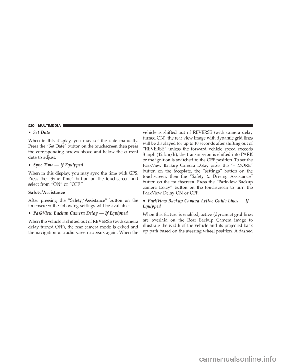
Tire Sizing Chart
EXAMPLE:
Example Size Designation: P215/65R15XL 95H, 215/65R15 96H, LT235/85R16C, T145/80D18 103M, 31x10.5 R15 LT
P = Passenger car tire size based on U.S. design standards, or
�....blank....� = Passenger car tire based on European design standards, or
LT = Light truck tire based on U.S. design standards, or
TorS= Temporary spare tire or
31 = Overall diameter in inches (in)
215, 235, 145 = Section width in millimeters (mm)
65, 85, 80 = Aspect ratio in percent (%)
– Ratio of section height to section width of tire, or
10.5 = Section width in inches (in)
9
MAINTAINING AND CARING FOR YOUR VEHICLE 479
Page 522 of 587

•Set Date
When in this display, you may set the date manually.
Press the “Set Date” button on the touchscreen then press
the corresponding arrows above and below the current
date to adjust.
• Sync Time — If Equipped
When in this display, you may sync the time with GPS.
Press the “Sync Time” button on the touchscreen and
select from “ON” or “OFF.”
Safety/Assistance
After pressing the “Safety/Assistance” button on the
touchscreen the following settings will be available:
• ParkView Backup Camera Delay — If Equipped
When the vehicle is shifted out of REVERSE (with camera
delay turned OFF), the rear camera mode is exited and
the navigation or audio screen appears again. When the vehicle is shifted out of REVERSE (with camera delay
turned ON), the rear view image with dynamic grid lines
will be displayed for up to 10 seconds after shifting out of
“REVERSE” unless the forward vehicle speed exceeds
8 mph (12 km/h), the transmission is shifted into PARK
or the ignition is switched to the OFF position. To set the
ParkView Backup Camera Delay press the “+ MORE”
button on the faceplate, the “settings” button on the
touchscreen, then the “Safety & Driving Assistance”
button on the touchscreen. Press the “Parkview Backup
camera Delay” button on the touchscreen to turn the
ParkView Delay ON or OFF.
•
ParkView Backup Camera Active Guide Lines — If
Equipped
When this feature is enabled, active (dynamic) grid lines
are overlaid on the Rear Backup Camera image to
illustrate the width of the vehicle and its projected back
up path based on the steering wheel position. A dashed
520 MULTIMEDIA
Page 523 of 587

center line overlay indicates the center of the vehicle to
assist with parking or aligning to a hitch/receiver.
•ParkView Backup Camera Fixed Guide Lines — If
Equipped
When this feature is enabled, fixed (static) grid lines are
overlaid on the Rear Backup Camera image to illustrate
the width of the vehicle.
• Forward Collision Warning-Plus (FCW+) — If
Equipped
The Front Collision Warning (FCW+) feature can be can
be set to Far, or set to Near. The default status of FCW+
is the Far setting. This means the system will warn you of
a possible collision with the vehicle in front of you when
you are farther away. This gives you the most reaction
time. To change the setting for a more dynamic driving
experience, select the Near setting. This warns you of a possible collision when you are much closer to the
vehicle in front of you. To change the FCW+ status, press
and release the “Near” or “Far” button.
•
Forward Collision Warning-Plus (FCW+) Active
Braking — If Equipped
The FCW+ system includes Advanced Brake Assist
(ABA). When this feature is selected, it will apply the
brakes to slow your vehicle in case of potential forward
collision. The ABA applies additional brake pressure
when the driver requests insufficient brake pressure to
avoid a potential frontal collision. The ABA system
becomes active at 5 mph (8 km/h).
For further information, refer to “Forward Collision
Warning-Plus (FCW+) With Mitigation” in “Safety.”
• ParkSense — If Equipped
The ParkSense system will scan for objects behind the
vehicle when the transmission shift lever/gear selector is
11
MULTIMEDIA 521