Page 411 of 587
3. Connect the negative(-)end of the jumper cable to the
negative (-)post of the booster battery.
4. Connect the opposite end of the negative (-)jumper
cable to a good engine ground (exposed metal part of
the discharged vehicle’s engine) away from the battery
and the fuel injection system.
WARNING!
Do not connect the jumper cable to the negative (-)
post of the discharged battery. The resulting electri-
cal spark could cause the battery to explode and
could result in serious injury. Only use the specific
ground point, do not use any other exposed metal
parts. 5. Start the engine in the vehicle that has the booster
battery, let the engine idle a few minutes, and then
start the engine in the vehicle with the discharged
battery.
6. Once the engine is started, remove the jumper cables in the reverse sequence:
Disconnecting The Jumper Cables
1. Disconnect the negative (-)end of the jumper cable
from the engine ground of the vehicle with the dis-
charged battery.
2. Disconnect the opposite end of the negative (-)jumper
cable from the negative (-)post of the booster battery.
3. Disconnect the positive (+)end of the jumper cable
from the positive (+)post of the booster battery.
8
IN CASE OF EMERGENCY 409
Page 412 of 587
4. Disconnect the opposite end of the positive(+)jumper
cable from the positive (+)post of the vehicle with the
discharged battery.
If frequent jump starting is required to start your vehicle
you should have the battery and charging system in-
spected at your authorized dealer.
CAUTION!
Accessories plugged into the vehicle power outlets
draw power from the vehicle’s battery, even when not
in use (i.e., cellular devices, etc.). Eventually, if
plugged in long enough without engine operation,
the vehicle’s battery will discharge sufficiently to
degrade battery life and/or prevent the engine from
starting.
ENHANCED ACCIDENT RESPONSE SYSTEM
In the event of an impact, if the communication network
remains intact, and the power remains intact, depending
on the nature of the event, the ORC will determine
whether to have the Enhanced Accident Response Sys-
tem perform the following functions:
• Cut off fuel to the engine.
• Flash hazard lights as long as the battery has power or
until the hazard light button is pressed. The hazard
lights can be deactivated by pressing the hazard light
button.
• Turn on the interior lights, which remain on as long as
the battery has power or for 15 minutes from the
intervention of the Enhanced Accident Response Sys-
tem.
• Unlock the power door locks.
410 IN CASE OF EMERGENCY
Page 422 of 587
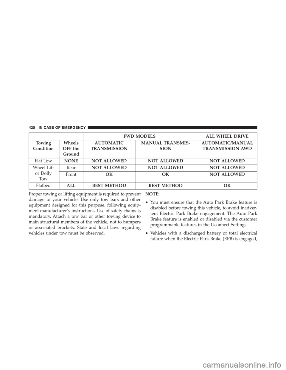
FWD MODELSALL WHEEL DRIVE
Towing
Condition Wheels
OFF the Ground AUTOMATIC
TRANSMISSION MANUAL TRANSMIS-
SION AUTOMATIC/MANUAL
TRANSMISSION AWD
Flat Tow NONE NOT ALLOWED NOT ALLOWED NOT ALLOWED
Wheel Lift or Dolly To w Rear
NOT ALLOWED NOT ALLOWED NOT ALLOWED
Front OK OKNOT ALLOWED
Flatbed ALL BEST METHOD BEST METHODOK
Proper towing or lifting equipment is required to prevent
damage to your vehicle. Use only tow bars and other
equipment designed for this purpose, following equip-
ment manufacturer ’s instructions. Use of safety chains is
mandatory. Attach a tow bar or other towing device to
main structural members of the vehicle, not to bumpers
or associated brackets. State and local laws regarding
vehicles under tow must be observed. NOTE:
•
You must ensure that the Auto Park Brake feature is
disabled before towing this vehicle, to avoid inadver-
tent Electric Park Brake engagement. The Auto Park
Brake feature is enabled or disabled via the customer
programmable features in the Uconnect Settings.
• Vehicles with a discharged battery or total electrical
failure when the Electric Park Brake (EPB) is engaged,
420 IN CASE OF EMERGENCY
Page 423 of 587
will need a wheel dolly or jack to raise the rear wheels
off the ground when moving the vehicle onto a flatbed.
If you must use the accessories (wipers, defrosters, etc.)
while being towed, the ignition must be in the MAR/
RUN position.
NOTE: The Safehold feature will engage the Electric Park
Brake whenever the driver’s door is opened (if the
ignition is ON, transmission is not in PARK, and brake
pedal is released). If you are towing this vehicle with the
ignition in the MAR/RUN position, you must manually
disable the Electric Park Brake each time the driver’s
door is opened, by pressing the brake pedal and then
releasing the EPB.
If the key fob is unavailable, or the vehicle’s battery is
discharged, refer to “Shift Lever Override” in this section
for instructions on shifting the transmission out of PARK
so that the vehicle can be moved.CAUTION!
• Do not use sling type equipment when towing.
Vehicle damage may occur.
• When securing the vehicle to a flat bed truck, do
not attach to front or rear suspension components.
Damage to your vehicle may result from improper
towing.
Front Wheel Drive (FWD) Models
The manufacturer recommends towing your vehicle with
all four wheels OFF the ground on a flatbed.
If flatbed equipment is not available, this vehicle must
towed with the front wheels OFF the ground (using a
towing dolly, or wheel lift equipment with the front
wheels raised).
8
IN CASE OF EMERGENCY 421
Page 431 of 587
MAINTAINING AND CARING FOR YOUR VEHICLE
CONTENTS
�EMISSIONS INSPECTION AND MAINTENANCE
PROGRAMS ......................... .431
� REPLACEMENT PARTS ..................432
� DEALER SERVICE ..................... .432
� MAINTENANCE SCHEDULE ..............433
▫ Maintenance Chart .....................435
� ENGINE COMPARTMENT — 1.4L TURBO
ENGINE ............................ .444
� ENGINE COMPARTMENT — 2.4L ENGINE . . . .445
� MAINTENANCE PROCEDURES ...........446▫
Engine Oil ......................... .446
▫ Engine Oil Filter ..................... .449
▫ Engine Air Cleaner Filter ................449
▫ Maintenance-Free Battery ...............450
▫ Air Conditioner Maintenance .............451
▫ Body Lubrication .....................452
▫ Wiper Blades ....................... .453
▫ Adding Washer Fluid ..................455
▫ Exhaust System ..................... .456
▫ Cooling System ..................... .458
9
Page 433 of 587
EMISSIONS INSPECTION AND MAINTENANCE
PROGRAMS
In some localities, it may be a legal requirement to pass
an inspection of your vehicle’s emissions control system.
Failure to pass could prevent vehicle registration.For states that require an Inspection and Mainte-
nance (I/M), this check verifies the “Malfunction
Indicator Light (MIL)” is functioning and is not
on when the engine is running, and that the OBD II
system is ready for testing.
Normally, the OBD II system will be ready. The OBD II
system may notbe ready if your vehicle was recently
serviced, recently had a dead battery or a battery replace-
ment. If the OBD II system should be determined not
ready for the I/M test, your vehicle may fail the test. Your vehicle has a simple ignition actuated test, which
you can use prior to going to the test station. To check if
your vehicle’s OBD II system is ready, you must do the
following:
1. Cycle the ignition switch to the ON position, but do
not crank or start the engine.
NOTE: If you crank or start the engine, you will have to
start this test over.
2. As soon as you cycle the ignition switch to the ON position, you will see the Malfunction Indicator Light
(MIL) symbol come on as part of a normal bulb check.
3. Approximately 15 seconds later, one of two things will happen:
• The MIL will flash for about 10 seconds and then
return to being fully illuminated until you turn OFF
9
MAINTAINING AND CARING FOR YOUR VEHICLE 431
Page 434 of 587
the ignition or start the engine. This means that your
vehicle’s OBD II system isnot readyand you should
not proceed to the I/M station.
• The MIL will not flash at all and will remain fully
illuminated until you place the ignition in the off
position or start the engine. This means that your
vehicle’s OBD II system is readyand you can proceed
to the I/M station.
If your OBD II system is not ready,you should see your
authorized dealer or repair facility. If your vehicle was
recently serviced or had a battery failure or replacement,
you may need to do nothing more than drive your
vehicle as you normally would in order for your OBD II
system to update. A recheck with the above test routine
may then indicate that the system is now ready.
Regardless of whether your vehicle’s OBD II system is
ready or not, if the MIL is illuminated during normal
vehicle operation you should have your vehicle serviced before going to the I/M station. The I/M station can fail
your vehicle because the MIL is on with the engine
running.
REPLACEMENT PARTS
Use of genuine parts for normal/scheduled maintenance
and repairs is highly recommended to ensure the de-
signed performance. Damage or failures caused by the
use of parts which are not quality-equivalent to genuine
parts for maintenance and repairs will not be covered by
the manufacturer ’s warranty.
DEALER SERVICE
Your authorized dealer has the qualified service person-
nel, special tools, and equipment to perform all service
operations in an expert manner. Service Manuals are
available which include detailed service information for
your vehicle. Refer to these Service Manuals before
attempting any procedure yourself.
432 MAINTAINING AND CARING FOR YOUR VEHICLE
Page 436 of 587
NOTE:Under no circumstances should oil change inter-
vals exceed 10,000 miles (16,000 km), twelve months or
350 hours of engine run time, whichever comes first. The
350 hours of engine run or idle time is generally only a
concern for fleet customers.
Severe Duty All Models
Change Engine Oil at 4,000 miles (6,500 km) if the vehicle is
operated in a dusty and off road environment or is operated
predominately at idle or only very low engine RPM’s. This
type of vehicle use is considered Severe Duty.
NOTE: The Oil Change Indicator will not illuminate
under these conditions.
Once A Month Or Before A Long Trip:
• Check engine oil level.
• Check windshield washer fluid level.
• Check the tire inflation pressures and look for unusual
wear or damage. •
Check the fluid levels of the coolant reservoir, and
brake master cylinder reservoir, and fill as needed.
• Check function of all interior and exterior lights.
Required Maintenance Intervals
At Every Oil Change Interval As Indicated By Oil Change Indicator System:
Change oil and filter.
Inspect battery and clean and tighten terminals as required.
Inspect brake pads, shoes, rotors, drums, and hoses. Inspect engine cooling system protection and hoses. Check and adjust hand brake.Inspect exhaust system.
Inspect engine air filter if using in dusty or off-road conditions.
Refer to the “Maintenance Chart” on the following page
for the required maintenance intervals.
434 MAINTAINING AND CARING FOR YOUR VEHICLE