Page 63 of 587
NOTE:If “Unlock All Doors 1st Press” is programmed in
EVIC/DID, if equipped, all doors will unlock when you
push the Electronic Release. If �Unlock Driver Door 1st
Press� is programmed in Uconnect, the liftgate will
unlock when you push the electronic lock/unlock button
on the liftgate. For further information, refer to
“Uconnect Settings” in “Multimedia.”
To Lock The Liftgate
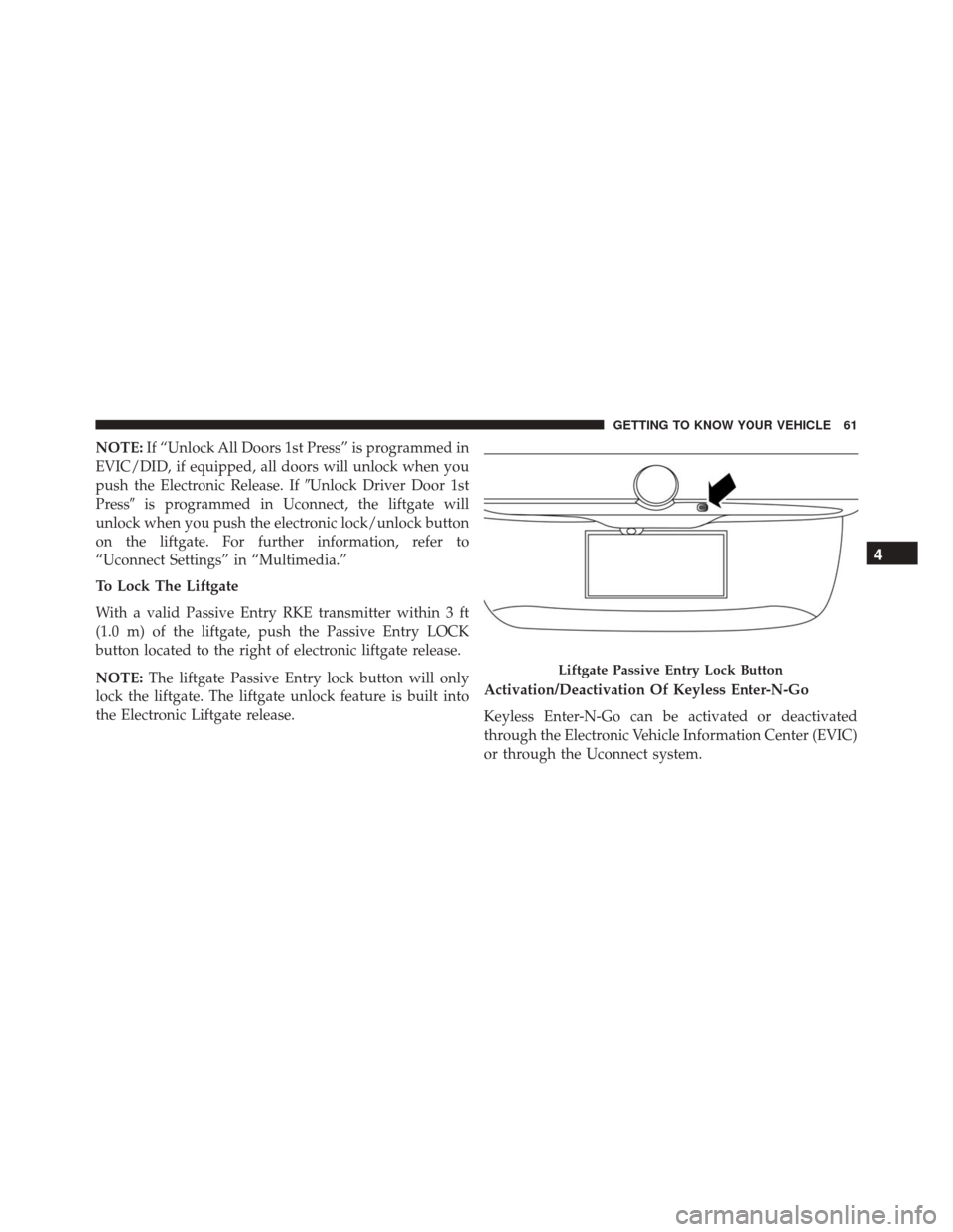
With a valid Passive Entry RKE transmitter within 3 ft
(1.0 m) of the liftgate, push the Passive Entry LOCK
button located to the right of electronic liftgate release.
NOTE: The liftgate Passive Entry lock button will only
lock the liftgate. The liftgate unlock feature is built into
the Electronic Liftgate release. Activation/Deactivation Of Keyless Enter-N-Go
Keyless Enter-N-Go can be activated or deactivated
through the Electronic Vehicle Information Center (EVIC)
or through the Uconnect system.
Liftgate Passive Entry Lock Button
4
GETTING TO KNOW YOUR VEHICLE 61
Page 64 of 587
Child Locks
To provide a safer environment for small children riding
in the rear seats, the rear doors are equipped with a
Child-Protection Door Lock system.
To use the system, open each rear door, use a flat blade
screwdriver (or ignition key) and rotate the dial to the
LOCK or UNLOCK position. When the system on a door
is engaged, that door can only be opened by using the
outside door handle even if the inside door lock is in the
unlocked position.
Child-Protection Door Lock Location
62 GETTING TO KNOW YOUR VEHICLE
Page 65 of 587
NOTE:
•When the child lock system is engaged, the door can
only be opened by using the outside door handle even
though the inside door lock is in the unlocked position.
• After disengaging the Child-Protection Door Lock
system, always test the door from the inside to make
certain it is in the desired position.
• After engaging the Child-Protection Door Lock sys-
tem, always test the door from the inside to make
certain it is in the desired position.
• For emergency exit with the system engaged, rotate
the lock button to the unlocked position, roll down the
window, and open the door with the outside door
handle.WARNING!
Avoid trapping anyone in a vehicle in a collision.
Remember that the rear doors can only be opened
from the outside when the Child-Protection locks are
engaged.
SEATS
Seats are a part of the Occupant Restraint System of the
vehicle.
4
GETTING TO KNOW YOUR VEHICLE 63
Page 73 of 587
4. Pull the seatback release lever to fold the left or rightrear seatback completely forward. Cargo Area Enlargement
Folding both sides of the rear seat provides additional
storage in the rear cargo area.
Proceed as follows:
1. Remove the rear shelf (if equipped).
2. Fully lower the rear seat head restraints.
3. Move the safety belts to the outboard side of the seat.
4. Pull the seatback release lever to fold both sides of the
rear seatbacks completely forward.
Seatback Repositioning
NOTE: If interference from the cargo area prevents the
seatback from fully locking, you will have difficulty
returning the seat to its proper position.
1. Move the safety belts to the seat belt guides on the top edge of the seat to ensure the seatbacks properly latch.
Seatback Release Lever
4
GETTING TO KNOW YOUR VEHICLE 71
Page 74 of 587
2. Lift the seatbacks, pushing them back until they lockon both the latches. Verify the red notches are no
longer visible on the release lever. If the red notches
are visible, the seatback is not secure.WARNING!
Be certain that the seatback is securely locked into
position. If the seatback is not securely locked into
position the seat will not provide the proper stability
for child seats and/or passengers. An improperly
latched seat could cause serious injury.
HEAD RESTRAINTS
Head restraints are designed to reduce the risk of injury
by restricting head movement in the event of a rear
impact. Head restraints should be adjusted so that the top
of the head restraint is located above the top of your ear.
Rear Seat Latch
72 GETTING TO KNOW YOUR VEHICLE
Page 79 of 587
To unlock the steering column, push the tilt/telescoping
lever downward (toward the floor). To tilt the steeringcolumn, move the steering wheel upward or downward
as desired. To lengthen or shorten the steering column,
pull the steering wheel outward or push it inward as
desired.
To lock the steering column in position, pull the tilt/
telescoping lever upward until fully engaged.
WARNING!
Do not adjust the steering column while driving.
Adjusting the steering column while driving or driv-
ing with the steering column unlocked, could cause
the driver to lose control of the vehicle. Failure to
follow this warning may result in serious injury or
death.
Heated Steering Wheel — If Equipped
The steering wheel contains a heating element that helps
warm your hands in cold weather. The heated steering
Tilt/Telescoping Steering Wheel
1 — Tilt/Telescoping Steering Wheel Lever
2 — Locked Position
3 — Unlocked Position
4
GETTING TO KNOW YOUR VEHICLE 77
Page 85 of 587
. The zone
length starts at the outside mirror and extends approxi-
mately 20 ft (6 m) beyond the re")
The BSM detection zone covers approximately one lane
width on both sides of the vehicle, 10 ft (3 m). The zone
length starts at the outside mirror and extends approxi-
mately 20 ft (6 m) beyond the rear bumper of the vehicle.
The BSM system monitors the detection zones on both
sides of the vehicle when the vehicle speed reaches
approximately 6 mph (10 km/h) or higher and will alert
the driver of vehicles in these areas.
NOTE:
•The BSM system does NOT alert the driver about
rapidly approaching vehicles that are outside the de-
tection zones.
• If a trailer is connected to the vehicle, it is necessary to
deactivate BSM system manually by settings menu to
avoid a miss-detection. Refer to “Uconnect Settings” in
“Multimedia” for further information. The area on the rear fascia where the radar sensors are
located must remain free of snow, ice, and dirt/road
contamination so that the BSM system can function
properly. Do not block the radar sensors located on the
rear fascia with foreign objects (bumper stickers, bicycle
racks, etc.).
Rear Sensor Locations
4
GETTING TO KNOW YOUR VEHICLE 83
Page 90 of 587
WARNING!
The Blind Spot Monitoring system is only an aid to
help detect objects in the blind spot zones. The BSM
(Continued)
WARNING!(Continued)
system is not designed to detect pedestrians, bicy-
clists, or animals. Even if your vehicle is equipped
with the BSM system, always check your vehicles
mirrors, glance over your shoulder, and use your turn
signal before changing lanes. Failure to do so can
result in serious injury or death.
Rear Cross Path (RCP)
The Rear Cross Path (RCP) feature is intended to aid the
driver when backing out of parking spaces where their
vision of oncoming vehicles may be blocked. Proceed
slowly and cautiously out of the parking space until the
rear end of the vehicle is exposed. The RCP system will
then have a clear view of the cross traffic and if an
oncoming vehicle is detected, alert the driver.
Opposing Traffic
88 GETTING TO KNOW YOUR VEHICLE


. To tilt the steeringcolumn, move the steering wheel upward or downward
as desired. To lengthen or shorten th")

WARNING!(Continued)
system is not designed to detect pedestrians, bicy-
cli")