Page 147 of 308

145
The three fuseboxes are located in the
dashboard on the left-hand side, in the
right-hand side pillar and in the engine
compartment.
The descriptions provided cover only the
fuses that can be replaced by the user. For
any other replacement, go to a CITROËN
dealer or a qualified workshop.
removing and fitting a fuse
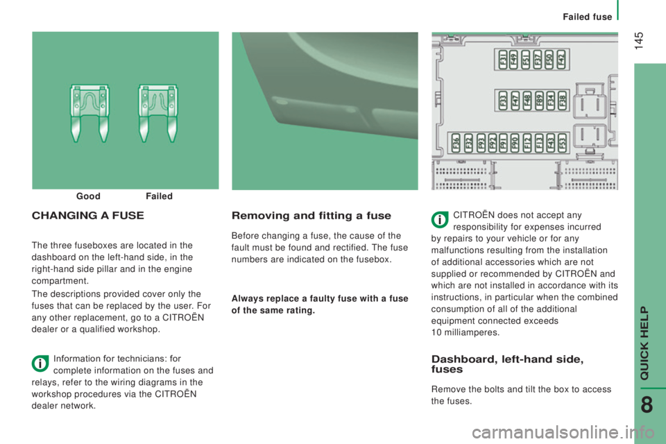
Before changing a fuse, the cause of the
fault must be found and rectified. The fuse
numbers are indicated on the fusebox.
Always replace a faulty fuse with a fuse
of the same rating.
cHAnGInG A Fu SECITROËN does not accept any
responsibility for expenses incurred
by repairs to your vehicle or for any
malfunctions resulting from the installation
of additional accessories which are not
supplied or recommended by CITROËN and
which are not installed in accordance with its
instructions, in particular when the combined
consumption of all of the additional
equipment connected exceeds
10 milliamperes.
Good
Failed
Information for technicians: for
complete information on the fuses and
relays, refer to the wiring diagrams in the
workshop procedures via the CITROËN
dealer network.
dashboard, left-hand side,
fuses
Remove the bolts and tilt the box to access
the fuses.
QUICK HELP
8
Failed fuse
Page 148 of 308

146FusesA (amps) Allocation
12 7.5Right-hand dipped headlamp
13 7.5Left-hand dipped headlamp
31 5Engine compartment control unit relay - Dashboard control unit relay (i\
gnition switch +)
32 7.5Cabin lighting (battery +)
33 7.5Battery check sensor on Stop & Start version (battery +)
34 7.5Minibus interior lighting - Hazard warning lamps
36 10Audio system - Air conditioning controls - Alarm - Tachograph - Battery cut-off control unit - Additional
heating programmer (battery +)
37 7.5Brake lamp switch - Third brake lamp - Instrument panel (ignition +)
38 20Central door locking (battery +)
42 5ABS control unit and sensor - ASR sensor - DSC sensor - Brake lamp switch
43 20Windscreen wiper motor (ignition switch +)
47 20Driver's electric window motor
48 20Passenger's electric window motor
49 5Parking sensors control unit - Audio system - Steering mounted controls - Centre and side switch panels\
-
Auxiliary switch panel - Battery cut-off control unit (ignition switch +)
50 7.5Airbags and pre-tensioners control unit
51 5Tachograph - Power steering control unit - Air conditioning - Reversing lamps - Water in Diesel sensor -
Air
flow sensor (ignition switch +)
53 7.5Instrument panel (battery +)
89 -Not used
90 7.5Left-hand main beam
91 7.5Right-hand main beam
92 7.5Left-hand front foglamp
93 7.5Right-hand front foglamp
Failed fuse
Page 149 of 308
147
door pillar, right-hand side,
fuses
Unclip the cover
When you have finished, close the cover
carefully. Fuses
A (amps) Allocation
54 -Not used
55 15Heated seats
56 15Rear passenger 12 V socket
57 10Under seat additional heating
58 15Heated rear screen, left-hand
59 15Heated rear screen, right-hand
60 -Not used
61 -Not used
62 -Not used
63 10Rear passenger additional control
64 -Not used
65 30Rear passenger additional heating fan
QUICK HELP
8
Failed fuse
Page 150 of 308
148
Fuses in the engine
compartment
Remove the nuts and tilt the box to access
the fuses.
r
efit the cover carefully after checking or
replacing fuses. Fuses
A (amps) Allocation
1 40ABS pump supply
2 50Diesel pre-heat unit
3 30Ignition switch - Starter motor
4 40Fuel heater
5 20/50Cabin ventilation with additional programmable heating
(battery +)
6 40/60Cabin fan maximum speed (battery +)
7 40/50/60 Cabin fan minimum speed (battery +)
8 40Cabin fan assembly (ignition switch +)
9 15Rear 12 V socket (battery +)
10 15Horn
11 -Not used
14 15Front 12 V socket (battery +)
15 15Cigarette lighter (battery +)
16 -Not used
17 -Not used
18 7.5Engine management control unit (battery +)
19 7.5Air conditioning compressor
20 30Screenwash/headlamp wash pump
21 15Fuel pump supply
22 -Not used
23 30ABS electrovalves
24 7.5Auxiliary switch panel - Door mirror controls and folding
(ignition switch +)
30 15Door mirror heating
Failed fuse
Page 269 of 308
267
SymptomElectricalHydraulic Verification / c heck
The unit operates but
does not generate
pressure. X
Valve slider jammed if no electrovalve on the unit.
Refer to the "Servicing" section.
X Pressure relief, adjustment, cleanliness.
X Pump seal failed.
X Motor / pump coupling.
X Pump loose on its bracket.
The hydraulic unit does
not operate. XElectrovalve jammed, replace it or tighten the nut behind
the strainer.
The control unit does
not operate. X
Check the connections and contacts.
Emulsion in the
reservoir. X
Return pipe incorrectly fitted.
X Fluid level to low.
Fluid discharged from
the breather. X
Too much fluid.
X Breather diaphragm tolerance a little wide, to be replaced.
Only valid for UD2386 units.
The fuse blows when
going down. X
Replace the return valve winding.
SPECIAL FEATURES
Tipper body