Page 190 of 366

188
C5_en_Chap08_information_ed01-2015
Removing a wheel
F Park the vehicle on stable, firm ground that
is not slippery. apply the parking brake.
F If your vehicle is equipped with
"Hydractive III+" suspension, with the
engine running at idle, adjust the ground
clearance to its maximum height.
F Switch off the ignition and engage first gear
(position P for an automatic gearbox).
F If your vehicle is fitted with "Hydractive III+"
suspension, position the chock, whichever
direction the gradient may be in, in front of
the front wheel diametrically opposite to
the one to be replaced.
List of operations
F Remove the protector from each bolt using
tool 3 .
F Fit the security bolt socket to the
wheelbrace to slacken the security bolt
(depending on equipment).
F Slacken the other bolts using just the
wheelbrace 1 .
Before positioning the jack:
F
Always adjust the vehicle’s ground
clearance to the "maximum height"
position and retain this adjustment
for as long as the jack is under the
vehicle (do not use the hydraulic
adjustments),
F Ensure that any passengers have
left the vehicle and are in a safe
place.
Never go underneath the vehicle if it is
supported only by the jack.
The jack and all of the tools are specific
to your vehicle. Do not use them for any
other purposes.
Have the original wheel repaired and
refitted as soon as possible.
Practical information
Page 192 of 366
190
C5_en_Chap08_information_ed01-2015
List of operations
Fitting a wheel
Wheel for temporary use
Your vehicle may be fitted with a spare wheel
which is different to those on the vehicle. When
fitting the spare wheel, it is normal to notice
that the wheel bolt washers do not come into
contact with the wheel rim. The spare wheel is
secured by the conical tapering of the wheel
bolt’s shaft.
When refitting the original wheel, ensure that
the wheel bolt contact sur faces are clean and
in good condition. F
Lower the vehicle to the ground.
F Lower the jack 2 and remove it.
F
Fit the wheel on the hub.
F Fit and tighten the bolts by hand.
F Pre-tighten the security bolt using
wheelbrace 1 and security bolt socket
(depending on equipment).
F Pre-tighten the other bolts using just the
wheelbrace 1 .
Practical information
Page 193 of 366

191
C5_en_Chap08_information_ed01-2015
If your vehicle is fitted with a spare
wheel of a different size to those on the
vehicle, you must not exceed 50 mph
(80 km/h) whilst using the spare wheel.
The wheel bolts are specific to the type
of wheel.
If the type of wheel is changed,
check with your CITROËN dealer or a
qualified workshop that the wheel bolts
are compatible with the new wheels.
Take care to note down the code
number engraved on the head of the
security bolt socket. This will enable
you to obtain a replacement security
bolt socket from your dealer.
F
Tighten the security bolt using
wheelbrace 1 and security bolt socket
(depending on equipment).
F Tighten the other bolts using just the
wheelbrace 1 .
F Refit the protectors on the bolts.
F Stow the tools in the carrier box.
F Return the suspension to the normal
position.
F Check that the tyre pressure is correct and
have the balancing checked.Tyre under-inflation detection
The space-saver type or steel spare
wheel does not have a sensor.
The punctured wheel must be repaired
by a CITROËN dealer or a qualified
workshop.
8
Practical information
Page 199 of 366
197
C5_en_Chap08_information_ed01-2015
Rear lamps (Saloon)
Identify the failed bulb.
1. Brake lamps and sidelamps: P21W/5 W
2. Sidelamps: R5W
3. Reversing lamps: H21W
4. Foglamps: H21W
5. Direction indicators: PY21WBoot lid-mounted lamps
F Refit the bulb holder H .
F Check that the bulb holder H is secured
correctly by the two clips E .
F Refit the connector G .
F Replace and fix the trim F with its 3 clips.
F
Open the boot.
F Using a flat screwdriver, remove the 3 clips
which fix the trim in the lamp area.
F Partially remove the trim F .
F d isconnect the connector G .
F Unclip the bulb holder H .
F Replace the failed bulb.
8
Practical information
Page 206 of 366

204
C5_en_Chap08_information_ed01-2015
Changing a fuse
The 2 fuseboxes are located below the dashboard and under the bonnet.
Replacing a fuse
Before replacing a fuse, you must:
- ascertain the cause of the fault and have it
remedied,
- switch off all electrical consumers,
- park the vehicle and switch off the ignition,
- identify the failed fuse using the allocation
tables and diagrams presented on the
following pages. Good
Failed
Tw e e z e r
If the fault recurs soon after replacing the
fuse, have the electrical system checked by a
CITROËN dealer or a qualified workshop. When replacing a fuse, it is essential to:
- use the special tweezer, located on the
cover close to the fusebox, to extract
the fuse from its housing and check the
condition of its filament,
- always replace a failed fuse with one of
equivalent rating (same colour); using a
different rating could cause a malfunction
(risk of fire). The replacement of a fuse not
mentioned in the tables below may
cause a serious malfunction on your
vehicle. Contact a CITROËN dealer or a
qualified workshop.CITR
oËn will not accept any
responsibility for the costs incurred
in repairing your vehicle or for the
malfunctions resulting from the
installation of auxiliary accessories which
were not supplied or recommended by
CITR oËn and which were not installed
in accordance with its instructions, in
particular where the current consumption
of all the the additional equipment
connected exceeds 10 milliamps.Installation of electrical
accessories
Your vehicle's electrical system is
designed to operate with standard or
optional equipment.
Before installing other electrical
equipment or accessories on your
vehicle, contact a CITR oËn dealer or a
qualified workshop.
Practical information
Page 209 of 366

207
C5_en_Chap08_information_ed01-2015
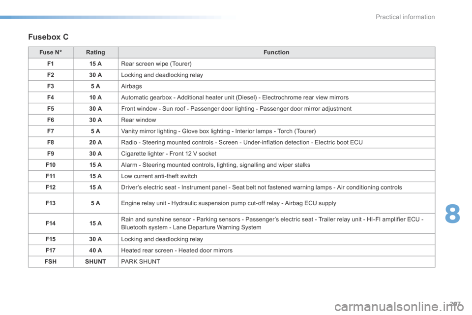
Fusebox C
Fuse N°Rating Function
F1 15 ARear screen wipe (Tourer)
F2 30 ALocking and deadlocking relay
F3 5 AAirbags
F4 10 AAutomatic gearbox - Additional heater unit (Diesel) - Electrochrome rear view mirrors
F5 30 AFront window - Sun roof - Passenger door lighting - Passenger door mirror adjustment
F6 30 ARear window
F7 5 AVanity mirror lighting - Glove box lighting - Interior lamps - Torch (Tourer)
F8 20 ARadio - Steering mounted controls - Screen - Under-inflation detection - Electric boot ECU
F9 30 ACigarette lighter - Front 12 V socket
F10 15 AAlarm - Steering mounted controls, lighting, signalling and wiper stalks
F11 15 ALow current anti-theft switch
F12 15 ADriver’s electric seat - Instrument panel - Seat belt not fastened warning lamps - Air conditioning controls
F13 5 AEngine relay unit - Hydraulic suspension pump cut-off relay - Airbag ECU supply
F14 15 ARain and sunshine sensor - Parking sensors - Passenger’s electric seat - Trailer relay unit - HI-FI amplifier ECU -
Bluetooth system - Lane Departure Warning System
F15 30 ALocking and deadlocking relay
F17 40 AHeated rear screen - Heated door mirrors
FSH SHUNTPaRk S H U nT
8
Practical information
Page 212 of 366

210
C5_en_Chap08_information_ed01-2015
12 V battery
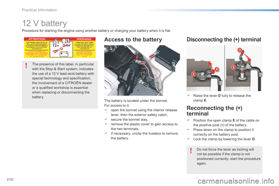
Access to the battery
The battery is located under the bonnet.
For access to it:
F open the bonnet using the interior release
lever, then the exterior safety catch,
F secure the bonnet stay,
F remove the plastic cover to gain access to
the two terminals,
F if necessary, unclip the fusebox to remove
the battery. F
Raise the lever D fully to release the
clamp E .
Disconnecting the (+) terminal
The presence of this label, in particular
with the Stop & Start system, indicates
the use of a 12 V lead-acid battery with
special technology and specification;
the involvement of a CITROËN dealer
or a qualified workshop is essential
when replacing or disconnecting the
battery.
Procedure for starting the engine using another battery or charging your battery when it is flat.
Reconnecting the (+)
terminal
F
Position the open clamp E of the cable on
the positive post (+) of the battery.
F Press down on the clamp to position it
correctly on the battery post.
F Lock the clamp by lowering the lever D .
Do not force the lever as locking will
not be possible if the clamp is not
positioned correctly; start the procedure
again.
Practical information
Page 220 of 366

218
C5_en_Chap08_information_ed01-2015
Roof bars
The design of your vehicle requires the use
of roof bars that are tested and approved by
CITROËN, for your safety and to avoid damage
to the roof and tailgate.
Regardless of the type of loading equipment
to be transported on the roof (bicycle carrier,
ski carrier...), it is imperative that you add
transverse roof bars. Any securing or lashing to
components other than the roof bars is strictly
prohibited.
Recommendations
F Distribute your load evenly, avoiding
overloading on one side.
F Arrange the heaviest part of the load as
close as possible to the roof.
F a nchor the load securely and draw
attention to it if any part of it is
overhanging.
F Drive gently, as the vehicle will be more
liable to the effects of side winds (vehicle
stability may be altered).
F Remove the roof bars as soon as they are
no longer needed. Maximum load that can be distributed
on the roof bars (for a loading height
not exceeding 40 cm; except bicycle
carrier): 80 kg.
If the height exceeds 40 cm, adapt your
speed to the profile of the road to avoid
damaging the roof bars and the fixings
on the roof.
Please refer to national legislation in
order to comply with the regulations
concerning the transportation of objects
which are longer than the vehicle.
Practical information