2016 BMW M4 service
[x] Cancel search: servicePage 94 of 228
Language
Setting the language
To set the language on the Control Display:1."Settings"2."Language/units"3."Language:"4.Select the desired language.
The setting is stored for the currently used
profile.
Setting the speech dialogue Voice dialogue for the voice control system,
see page 26.
Units of measure
Setting the units of measure
To set the units of measure for fuel consump‐
tion, distance covered/remaining range, and
temperature:
1."Settings"2."Language/units"3.Select the desired menu item.4.Select the desired unit.
The setting is stored for the currently used
profile.
Brightness
Adjusting brightness
Adjusting brightness of Control Display:
1."Settings"2."Control display"3."Brightness"4.Turn the Controller until the desired bright‐
ness is obtained.5.Press the Controller.
The setting is stored for the currently used
profile.
Depending on the lighting conditions, bright‐
ness control might not be immediately recog‐
nisable.
Head-Up Display
Overview
Principle
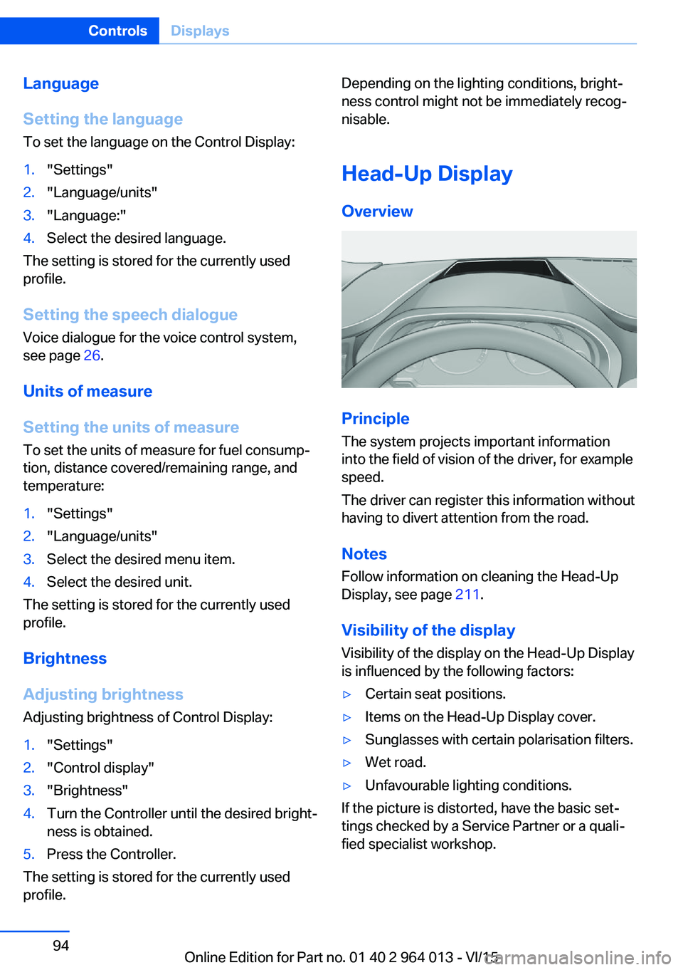
The system projects important information
into the field of vision of the driver, for example
speed.
The driver can register this information without
having to divert attention from the road.
Notes
Follow information on cleaning the Head-Up
Display, see page 211.
Visibility of the display Visibility of the display on the Head-Up Display
is influenced by the following factors:
▷Certain seat positions.▷Items on the Head-Up Display cover.▷Sunglasses with certain polarisation filters.▷Wet road.▷Unfavourable lighting conditions.
If the picture is distorted, have the basic set‐
tings checked by a Service Partner or a quali‐
fied specialist workshop.
Seite 94ControlsDisplays94
Online Edition for Part no. 01 40 2 964 013 - VI/15
Page 96 of 228
Adjusting rotation
The image of the Head-Up Display can be ro‐
tated around its axis.
On the Control Display:1."Settings"2."Head-up display"3."Rotation"4.Turn the Controller until the desired set‐
ting is reached.5.Press the Controller.
The setting is saved for the currently used pro‐
file.
Special windscreen
The windscreen constitutes part of the sys‐
tem.
The shape of the windscreen enables a precise
projection.
A film in the windscreen prevents double im‐
ages occurring.
For this reason, have the special windscreen
replaced by a Service Partner or a qualified
specialist workshop.
Shift Lights General
The display is on the Head-Up Display and in
the instrument cluster.
Shift Lights in the instrument cluster
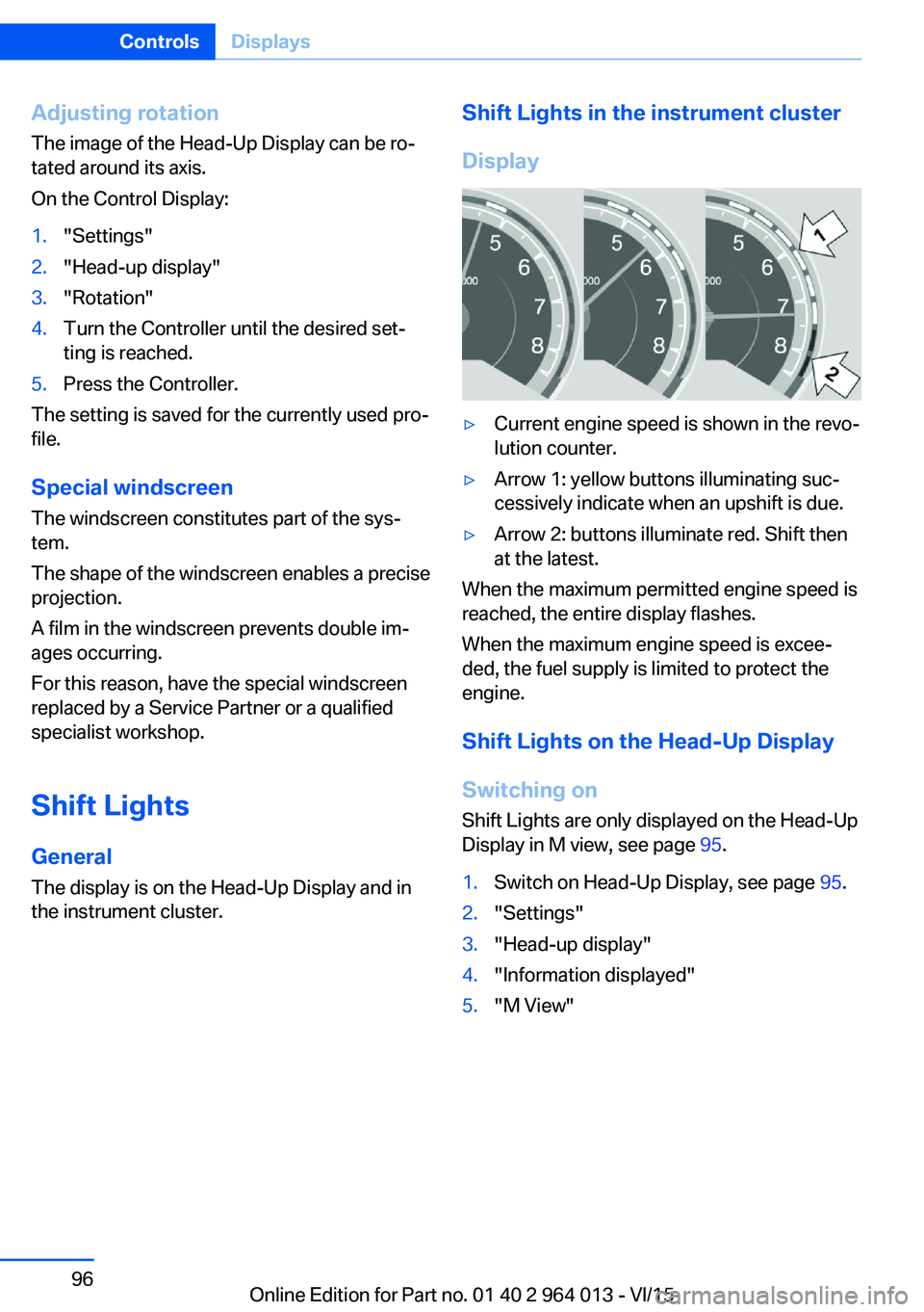
Display▷Current engine speed is shown in the revo‐
lution counter.▷Arrow 1: yellow buttons illuminating suc‐
cessively indicate when an upshift is due.▷Arrow 2: buttons illuminate red. Shift then
at the latest.
When the maximum permitted engine speed is
reached, the entire display flashes.
When the maximum engine speed is excee‐
ded, the fuel supply is limited to protect the
engine.
Shift Lights on the Head-Up DisplaySwitching on Shift Lights are only displayed on the Head-Up
Display in M view, see page 95.
1.Switch on Head-Up Display, see page 95.2."Settings"3."Head-up display"4."Information displayed"5."M View"Seite 96ControlsDisplays96
Online Edition for Part no. 01 40 2 964 013 - VI/15
Page 102 of 228
▷When the windscreen in front of the rear-
view mirror is covered with condensation,
dirt, stickers, labels, etc.
Fog lights
Rear fog lights
The low-beam headlights must be switched
on.
Press the button. The yellow indicator
light is illuminated.
If automatic driving lights control, see page 99,
has been activated, the low-beam headlights
come on automatically when the rear fog lights
are switched on.
Left-hand/right-hand traffic GeneralWhen driving in countries where the opposite
rule of the road applies, you need to prevent
your headlights from dazzling oncoming vehi‐
cles.
Xenon headlight
Light distribution of the headlights avoids daz‐
zling of the low-beam headlights when driving
in a country in which the traffic drives on the
opposite side.
Adaptive Headlights
When driving in a country where you drive on
the opposite side of the road from the country
the vehicle is licensed, do not drive with the
setting, otherwise this could cause a daz‐
zling effect from the variable light distribution.
LED headlights The Service Partner or a qualified specialist
workshop has light benders available. Proceed
in accordance with the enclosed information
when affixing the light benders to the head‐
lights.
Adaptive Headlights
When driving in a country where you drive on
the opposite side of the road from the country
the vehicle is licensed, do not drive with the
setting, otherwise this could cause a daz‐
zling effect from the variable light distribution.
Instrument lightingAdjusting The brightness can only be ad‐justed when the side lights or
the low-beam headlights are
switched on.
The brightness can be set using
the knurled wheel.
Interior light GeneralThe interior light, the footwell lights, door entry
lighting and the courtesy lighting are controlled
automatically.
The brightness of some equipment is influ‐
enced by the knurled wheel for the instrument
lighting.
Seite 102ControlsLights102
Online Edition for Part no. 01 40 2 964 013 - VI/15
Page 105 of 228

Notes on optimum protective effect of
the airbag
WARNING
If the seat position is wrong or the de‐
ployment area of the airbag is impaired, the air‐
bag system cannot provide the intended pro‐
tection, or may cause additional injuries when
it deploys. Danger of injury or life. Comply with
these notes for optimum protective effect.◀▷Keep your distance from the airbags.▷Make sure that vehicle occupants keep
their head away from the side airbag.▷Always grip the steering wheel on the
steering wheel rim. Keep you hands in the
3 o'clock and 9 o'clock positions to reduce
the risk of injury to hands or arms when the
airbag deploys.▷Make sure that the front-seat passenger is
sitting correctly, in other words with feet or
legs in the footwell, not resting on the
dashboard.▷Do not position any other persons, pets or
objects between the airbags and persons.▷Never attach any material to the airbag
covers with adhesive; never place material
over them or modify them in any way.▷Keep the dashboard and windscreen in the
area of the passenger's side free, for exam‐
ple do not attach adhesive foil or covers
and do not fit brackets for navigation devi‐
ces or mobile telephones.▷Do not use the front airbag cover on the
front passenger's side as a tray.▷Do not fit seat covers, cushions or other
objects not specifically suitable for seats
with integral side airbags to the front seats.▷Do not hang items of clothing such as
coats or jackets over the backrests.▷Do not modify individual components of
the system or its wiring in any way. This
also applies to the covers of the steering
wheel, the dashboard and seats.▷Do not dismantle the airbag system.
Even if all these notes are complied with, de‐
pending on the circumstances in which an ac‐
cident occurs, certain injuries as a result of
contact with the airbag cannot be entirely ruled
out.
The noise caused by the deployment of an air‐
bag may lead to temporary hearing loss for ve‐
hicle occupants sensitive to noise.
Operational readiness of the airbag
system
Notes WARNING
Individual components of the airbag sys‐
tem can be hot after triggering. Danger of in‐ jury. Do not touch individual components.◀
WARNING
Work carried out incorrectly can lead to a
failure, a malfunction or accidental triggering of
the airbag system. If there is a malfunction, the
airbag system might not trigger as intended in
an accident, in spite of the accident being of
the appropriate severity. Danger of injury or
life. Have the airbag system tested, repaired or
removed and scrapped by a Service Partner or a qualified specialist workshop.◀
Correct function When the ignition is switched on, the
warning light in the instrument cluster
briefly illuminates in order to show the
functional readiness of the entire airbag sys‐
tem and the belt tensioner.
Airbag system disrupted
▷Warning light does not illuminate after the
ignition is switched on.▷Warning lamp is permanently illuminated.Seite 105SecurityControls105
Online Edition for Part no. 01 40 2 964 013 - VI/15
Page 108 of 228
cepted as target values. The reset is run auto‐
matically while the vehicle is in motion.
After a successfully concluded reset, the
wheels are shown in green on the Control Dis‐
play and "Tyre Pressure Monitor (RDC)
active." is shown.
You can interrupt your drive at any time. Reset
resumes automatically when you continue
your journey.
Message if tyre inflation pressure is
low
The yellow warning lamp is illuminated.
A Check Control message is shown.▷There is a flat tyre or substantial
loss of tyre pressure.▷No reset has been done to the system.
Consequently, the system warns of the
tyre pressures of the last reset.1.Reduce your speed and carefully stop the
vehicle. Avoid violent or sudden braking
and steering manoeuvres.2.Determine which wheel is damaged. Do
this by checking the tyre inflation pres‐
sures with the aid of the Mobility System.
Correcting the tyre inflation pressure3.Remedy the flat tyre with the Mobility Sys‐
tem or replace the damaged wheel.
When there is a message that the tyre inflation
pressure is low, the Dynamic Stability Control
DSC may be switched on.
Message with required tyre inflation
pressure test
In such situations, a check control message is
displayed:
▷System has detected a wheel change, but
no reset has been run.▷Filling was not performed according to the
regulations.▷The tyre inflation pressure has dropped
compared to the last confirmation.If that is the case:▷Check the tyre pressure and adjust as nec‐
essary.▷Reset the system after a wheel change.
System limits
The system is not working correctly if no reset
has been run, for example, a flat tyre is repor‐
ted in spite of the correct tyre inflation pres‐
sure.
Tyre inflation pressure depends on the tem‐
perature of the tyre. By increasing tyre temper‐
ature, for example, when driving or with solar
radiation, the tyre inflation pressure increases.
Tyre inflation pressure decreases if the tyre
temperature drops. Through this behaviour, a
warning may be triggered if there are major
temperature drops, due to the given warning
limits.
No warning can be given by the system of ex‐
treme, sudden tyre failure caused by external
factors.
Malfunction The yellow warning lamp flashes and is
then illuminated continuously. A Check
Control message is shown. No flat
tyres or loss of tyre pressure can be detected.
This may indicate one of the following:
▷Wheel without TPM electronics is fitted:
have the vehicle checked by a Service
Partner or a qualified specialist workshop if
necessary.▷Malfunction: have the system checked by a
Service Partner or a qualified specialist
workshop.▷TPM has not completed a reset. Run a re‐
set of the system again.▷Fault due to systems or devices with the
same frequency: the system is automati‐
cally reactivated upon leaving the field of
interference.Seite 108ControlsSecurity108
Online Edition for Part no. 01 40 2 964 013 - VI/15
Page 161 of 228

Drivetrain
In this vehicle, particular attention is paid to the
direct connection from the engine to the drive‐
train. Due to the torsionally stiff design of the
drivetrain, as usual in a sports car, the trans‐
mission of the torque is can also be heard.
When there are load changes, it can therefore
cause clattering noises. They do not affect the
functioning or durability of the components.
Driving on a racing track
Requirements For driving on a racing track:▷Participation in a training course from
BMW Driving Experience.▷Check engine oil level and top up with en‐
gine oil as required.▷Have vehicle checked by a Service Partner
or a qualified specialist workshop.
Notes
Racing track operation causes increased wear. The vehicle is not designed for use in motor‐
sport competitions. This wear is not covered by the warranty.
The standard brake pads and the wear dis‐
plays are not designed for racing track opera‐
tion. Further information and advice are avail‐
able from a Service Partner or a qualified
specialist workshop.
Seite 161BMW M4 TechnologyDriving hints161
Online Edition for Part no. 01 40 2 964 013 - VI/15
Page 162 of 228
Driving precautionsVehicle equipmentThis chapter describes all standard, national
and special equipment provided in the model
series. Equipment not available in the vehicle is
therefore also described, for example the se‐
lected special equipment or national version.
This also applies to safety-relevant functions
and systems. Comply with the relevant na‐
tional regulations when using the correspond‐
ing functions and systems.
Running in General
Moving parts need a certain time to achieve
maximum operating efficiency as a unit.
The following information helps to achieve
maximum service life and efficiency of the ve‐
hicle.
Do not use Launch Control, see page 77, when
running in.
Engine, gearbox and differential
Up to 2000 km, 1200 miles Drive with alternating revolutions and speeds,
but do not exceed 5500 rpm and 170 km/h, ap‐ proximately 106 mph.
In principle, avoid full load or kick-down.
At 2000 km, 1200 miles
Have maintenance conduct a drive-in service.
From 2000 km, approximately
1200 miles to 5000 km, approximately
3100 miles
Revolutions and vehicle speed can gradually
be increased to a continuous speed of
220 km/h, approximately 137 mph.The maximum speed of 250 km/h, approxi‐
mately 155 mph is only to be used briefly, for
example when overtaking.
Tyres New tyres do not achieve their full road
grip immediately, for production reasons.
During the first 300 km, 200 miles, drive mod‐
erately.
Brake system
Brake pads and discs of the M compound
brakes only achieve a favourable wear and
contact pattern after approximately 500 km,
approximately 300 miles. Drive moderately
during this running-in period.
Brake discs and pads of the M carbon ceramic
brakes only achieve a favourable wear and
contact pattern after approx. 1000 km, approx.
600 miles. Drive moderately during this run‐
ning-in period.
Clutch
The clutch only begins to function optimally at
approximately 500 km, approximately
300 miles. Engage the clutch gently during this
running-in period.
After fitting new parts The same running-in procedures should be
observed if any of the components mentioned
above have to be renewed in the course of the
vehicle's operating life.Seite 162Driving hintsDriving precautions162
Online Edition for Part no. 01 40 2 964 013 - VI/15
Page 163 of 228

General driving information
Closing the boot lid WARNING
An open boot lid projects beyond the ve‐
hicle, and in the event of an accident, braking
or avoidance manoeuvres, it can endanger ve‐ hicle occupants and other road users, or dam‐
age the vehicle. There is also the danger of ex‐
haust fumes entering the interior of the
vehicle. Danger of injury or damage to prop‐
erty. Do not drive with the boot lid open.◀
If there is no alternative to driving with the tail‐
gate open:▷Close all windows and the Glass Roof.▷Turn up the blower to a high output level.▷Maintain moderate speed.
Hot exhaust system
WARNING
During driving, high temperatures can be
generated under the body, for example be‐
cause of the exhaust system. If flammable ma‐
terials, for example leaves of grass, come into
contact with hot parts of the exhaust system,
these materials can catch fire. Danger of injury
or damage to property.
Never remove the heat shields fitted here, or
apply underseal to them. Make sure that when driving, idling or parking, no flammable materi‐
als can come into contact with hot vehicle
parts. Do not touch the hot exhaust system.◀
Radio signals WARNING
Certain vehicle functions may be affec‐
ted by interference from high-frequency radio
signals. Such signals are output from a series
of transmission systems, for example, from air
traffic beacons or relay stations for mobile tele‐
communications.
We recommend you consult a Service Partner
or a qualified specialist workshop should you
experience any difficulties.◀
Mobile communication equipment WARNING
The vehicle's electronics and mobile
radio devices can interfere. The transmission
operation of mobile radio devices generates
radiation. Danger of injury or damage to prop‐
erty. If possible, only use mobile radio devices,
e.g. mobile telephones, in the interior with di‐
rect connection to an external antenna to ex‐
clude mutual interference and to dissipate the
radiation from the vehicle's interior.◀
Aquaplaning
On wet or slushy roads, a wedge of water can
form between the tyres and the road.
This situation, known as aquaplaning, means
that the tyre can actually lose contact com‐
pletely with the road surface and the vehicle
can neither be steered nor the brakes properly
applied.
Wading ATTENTION
Driving through excessively deep water
too fast can result in water entering the engine
compartment, electrical system or transmis‐
sion. Danger of damage to property. When
driving through water, do not exceed the maxi‐
mum specified water depth and maximum
fording speed.◀
Only if the water is calm and only up to a water
depth of max. 25 cm, approximately 9.8 inches
and at this depth drive no faster than walking
speed up to 5 km/h, approximately 3 mph.
Safe braking Your vehicle is equipped with ABS as standard.Seite 163Driving precautionsDriving hints163
Online Edition for Part no. 01 40 2 964 013 - VI/15