Page 121 of 228

The MDM and DSC OFF indicator lights go
out.
Via M Drive On the Control Display:1."Settings"2."M Drive 1" or "M Drive 2"3. Select the symbol.4."MDM"
To open M Drive with the selected settings,
press the corresponding button on the steer‐
ing wheel:
▷▷
A message appears in the instrument cluster.
This message is confirmed by pressing the
button again.
Deactivating MDM
Press the appropriate button 1 or button 2 on
the steering wheel again.
M Dynamic Mode and the settings selected
under M Drive are deactivated.
Indicator/warning lights Indicator lights light up:
M Dynamic Mode is activated.
DSC indicator lamp also flashes:
M Dynamic Mode controls the drive
forces and brake forces.
Indicator lights light up:
M Dynamic Mode or DSC has failed.
Active M differential
The concept The active M differential assures continuously
variable locking of the rear axle differential de‐
pending on the driving situation. This prevents
individual rear wheels from spinning even
when DSC is switched off and in M Dynamic
Mode, so that optimum traction is always as‐
sured in all driving situations.
The driver is responsible adapting his or her
driving behavior to the situation.
Adaptive M chassis The conceptThis system reduces undesirable vehicle mo‐
tion when using a dynamic driving style or trav‐
eling on uneven road surfaces.
The system enhances driving dynamics and
comfort fitting road surface and driving style.
Programs Setting options for calibrating the shock ab‐
sorbers:▷"Comfort": comfort-oriented.▷"Sport": balanced out.▷"Sport Plus": consistently sporty.
Selecting a channel
Via M Drive
1."Settings"2."M Drive 1" or "M Drive 2"3. Select the symbol.4.Select the desired channel.
When M Drive is active, setting is immedi‐
ately applied.
To activate M Drive with the selected settings,
press the corresponding button on the steer‐
ing wheel:
Seite 117Driving stability control systemsControls117
Online Edition for Part no. 01 40 2 960 786 - II/15
Page 122 of 228

▷▷
Using the button
Press button repeatedly until the desired
program is displayed in the instrument
cluster.
Display in the instrument cluster Adaptive M chassis with selected pro‐
gram for the active display of driving
dynamics system statuses, refer to
page 83.
Drive-off assistant This system supports driving off on inclines.
The parking brake is not required.
1.Hold the vehicle in place with the foot
brake.2.Release the foot brake and drive off with‐
out delay.
After the foot brake is released, the vehicle is
held in place for approx. 2 seconds.
Depending on the vehicle load or when a trailer
is used, the vehicle may roll back slightly.
Driving off without delay
After releasing the foot brake, start driv‐
ing without delay, since the drive-off assistant
will not hold the vehicle in place for more than
approx. 2 seconds and the vehicle will begin to
roll back.◀
Servotronic The conceptThe Servotronic varies the steering force re‐
quired to turn the wheels in accordance with
the vehicle speed. At low speeds, the steering
force is strongly supported, i. e. during steer‐
ing, low force is required. As the speed in‐ creases, the assistance of the steering force is
reduced.
Furthermore, the steering force adapts accord‐
ing to the driving program, so that a direct, sporty feel and/or comfortable steering is con‐
veyed.
Programs Steering force setting options:▷"Comfort": low.▷"Sport": medium.▷"Sport Plus": high.
Selecting a channel
Via M Drive On the Control Display:
1."Settings"2."M Drive 1" or "M Drive 2"3. Select the symbol.4.Select the desired channel.
When M Drive is active, setting is immedi‐
ately applied.
To activate M Drive with the selected settings,
press the corresponding button on the steer‐
ing wheel:
▷▷Seite 118ControlsDriving stability control systems118
Online Edition for Part no. 01 40 2 960 786 - II/15
Page 123 of 228
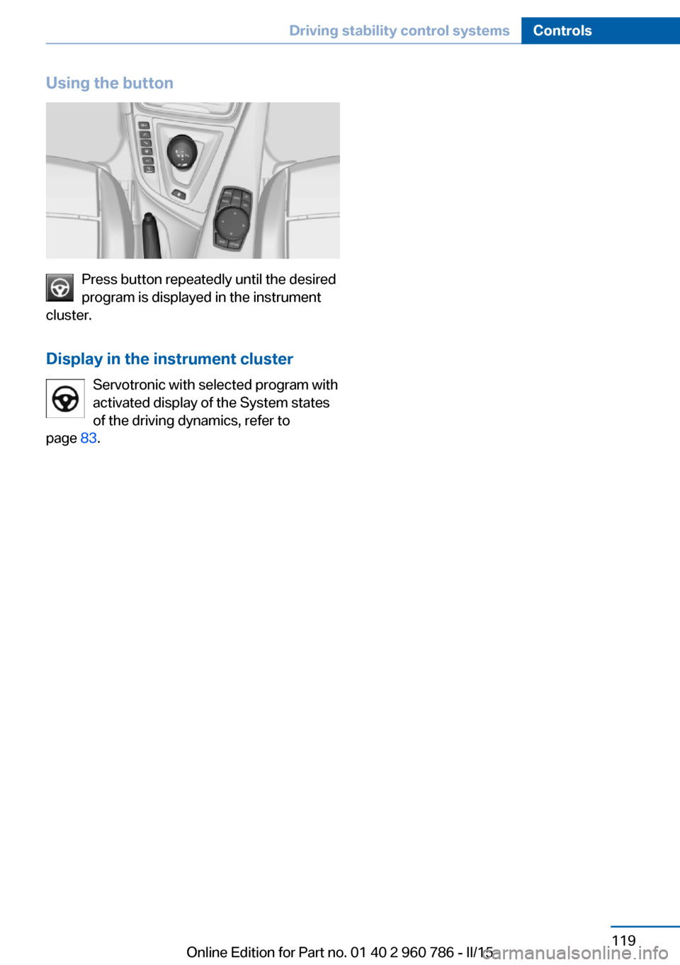
Using the button
Press button repeatedly until the desired
program is displayed in the instrument
cluster.
Display in the instrument cluster Servotronic with selected program with
activated display of the System states
of the driving dynamics, refer to
page 83.
Seite 119Driving stability control systemsControls119
Online Edition for Part no. 01 40 2 960 786 - II/15
Page 124 of 228

Driving comfortVehicle features and options
This chapter describes all standard, country-
specific and optional features offered with the
series. It also describes features that are not
necessarily available in your car, e. g., due to
the selected options or country versions. This
also applies to safety-related functions and
systems. The respectively applicable country
provisions must be observed when using the
respective features and systems.
Cruise control The concept The system maintains a preset speed via the
buttons on the steering wheel. The system brakes on downhill gradients if engine braking
is insufficient.
General information
Depending on the driving settings, the features
of the cruise control can change in certain
areas.
Hints Unfavorable conditions
Do not use the system if unfavorable
conditions make it impossible to drive at a con‐
stant speed, e.g.:▷On winding roads.▷In heavy traffic.▷On slippery roads, in fog, snow or rain, or
on a loose road surface.
Otherwise, you could lose control of the vehi‐
cle and cause an accident.◀
Overview
Buttons on the steering wheelPress buttonFunctionSystem on/off, interruptStore speedResume speedrocker switch: change, hold,
store speed
Controls
Switching on Press button on the steering wheel.
The marking in the speedometer is set to the
current speed.
Cruise control can be used.
Switch off Deactivated or interrupted system
With deactivated or interrupted system
use your brakes, steering and moves as usual
to avoid the chance of an accident.◀
Press button.
▷If active: press twice.▷If interrupted: press once.
The displays go out. The stored desired speed
is deleted.
Seite 120ControlsDriving comfort120
Online Edition for Part no. 01 40 2 960 786 - II/15
Page 125 of 228

InterruptingWhen active, press the button.
The system is automatically interrupted if:▷The brakes are applied.▷The clutch pedal is depressed for a few
seconds or released while a gear is not en‐
gaged.▷The gear engaged is too high for the cur‐
rent speed.▷MDM is activated or DSC is deactivated.▷DSC is actively controlling stability.
Maintaining, storing, and changing the
speed
Hints Adjusting the desired speed
Modify desired speed to road conditions
and be ready to brake at all times; otherwise,
there is the risk of an accident.◀
Maintaining/storing the speed Press button.
Or:
Press the rocker switch while the system is in‐
terrupted.
When the system is switched on, the current
speed is maintained and stored as the desired
speed.
This is displayed, refer to page 121, in the
speedometer and briefly in the instrument
cluster.
When cruise control is maintained or stored,
DSC Dynamic Stability Control will be turned
on if needed.
Changing the speed
Press the rocker switch up or down repeatedly
until the desired speed is set.
If active, the displayed speed is stored and the
vehicle reaches the stored speed when the
road is clear.▷Each time the rocker switch is pressed to
the point of resistance, the desired speed
increases or decreases by approx.
1 mph/1 km/h.▷Each time the rocker switch is pressed
past the point of resistance, the desired
speed increases or decreases by a maxi‐
mum of 5 mph/10 km/h.
The maximum speed that can be set de‐
pends on the vehicle.▷Pressing the rocker switch to the resist‐
ance point and holding it accelerates or de‐
celerates the vehicle without requiring
pressure on the accelerator pedal.
After the rocker switch is released, the ve‐
hicle maintains its final speed. Pressing the
switch beyond the resistance point causes
the vehicle to accelerate more rapidly.
Resuming the desired speed
Press button.
The stored speed is reached and maintained. Displays in the instrument cluster
Indicator lamp Depending on how the vehicle is equip‐
ped, the indicator lamp in the instru‐
Seite 121Driving comfortControls121
Online Edition for Part no. 01 40 2 960 786 - II/15
Page 126 of 228

ment cluster indicates whether the system is
switched on.
Desired speed▷The marking lights up green:
the system is active.▷The marking lights up or‐
ange: the system has been
interrupted.▷The marking does not light up: the system
is switched off.
Brief status display
Selected desired speed.
If --- appears briefly on the display for Check
Control messages, it is possible that the sys‐
tem requirements are currently not ready for
operations.
Displays in the Head-up Display Some system information can also be dis‐played in the Head-up Display.
PDC Park Distance Control
The concept PDC is a support when parking. When you
slowly approach an object in the rear - or also
in the front of the vehicle if the feature is availa‐
ble - then the object is reported through:
▷Signal tones.▷Visual display.
General information
Ultrasound sensors in the bumpers measure
the distances from objects.
The maneuvering range, depending on the ob‐
stacle and environmental conditions, is approx.
6 ft/2 m.
An acoustic warning is first given:▷By the front sensors and the two rear cor‐
ner sensors at approx. 24 in/60 cm.▷By the rear middle sensors at approx.
5 ft/1.50 m.
To ensure full functionality:
▷Do not cover sensors, e.g., with stickers,
bicycle racks.▷Keep the sensors clean and free of ice.▷When using high-pressure washers, do not
spray the sensors for long periods and
maintain a distance of at least 12 in/30 cm.
Hints
Personal responsibility
Even an active system does not relieve
the driver from personal responsibility while
driving.
Technically the system has its limits, it cannot
independently react to all traffic situations.
Monitor your driving, be on the alert, observe
the vehicle surroundings and other traffic and
react when needed - risk of accident.◀
Avoid driving fast with PDC
Avoid approaching an object too fast.
Avoid driving off fast while PDC is not yet ac‐
tive.
For technical reasons, the system may other‐
wise be too late in issuing a warning.◀
Seite 122ControlsDriving comfort122
Online Edition for Part no. 01 40 2 960 786 - II/15
Page 127 of 228

Overview
With front PDC: button in vehicle
PDC Park Distance Control
Switching on/off
Switching on automatically With the engine running, engage lever in posi‐
tion P R.
Automatic deactivation during forward
travel
The system switches off when a certain driving
distance or speed is exceeded.
Switch the system back on if needed.
With front PDC: switching on/off
manually
Press button.
▷On: the LED lights up.▷Off: the LED goes out.
Display
Signal tones When approaching an object, an intermittent
sound indicates the position of the object. E. g.
if an object is detected to the left rear of the
vehicle, a signal tone sounds from the left rear
speaker.
The shorter the distance to the object, the
shorter the intervals.
If the distance to a detected object is less than
approx. 10 in/25 cm, a continuous tone is
sounded.
With front PDC: if objects are located both in
front of and behind the vehicle, an alternating
continuous signal is sounded.
Volume
The volume of the PDC signal tone can be ad‐
justed similar to the sound and volume set‐
tings of the radio.
Settings are stored for the profile currently in
use.
Visual warning
The approach of the vehicle to an object can
be shown on the Control Display. Objects that
are farther away are already displayed on the
Control Display before a signal sounds.
A display appears as soon as Park Distance
Control (PDC) is activated.
The range of the sensors is represented in the
colors green, yellow and red.
When the image of the rearview camera is dis‐
played, the reel can be made to PDC:
"Rear view camera"
System limits
Limits of ultrasonic measurement
Ultrasonic measuring might not function under
the following circumstances:
▷For small children and animals.▷For persons with certain clothing, e.g.
coats.▷With external interference of the ultra‐
sound, e.g. from passing vehicles or loud
machines.▷When sensors are dirty, iced over, dam‐
aged or out of position.Seite 123Driving comfortControls123
Online Edition for Part no. 01 40 2 960 786 - II/15
Page 128 of 228

▷Under certain weather conditions such as
high relative humidity, rain, snowfall, ex‐
treme heat or strong wind.▷With tow bars and trailer couplings of other
vehicles.▷With thin or wedge-shaped objects.▷With moving objects.▷With elevated, protruding objects such as
ledges or cargo.▷With objects with corners and sharp edges.▷With objects with a fine surface structure
such as fences.▷For objects with porous surfaces.
Low objects already displayed, e.g., curbs, can
move into the blind area of the sensors before
or after a continuous tone sounds.
False warnings
PDC may issue a warning under the following conditions even though there is no obstacle
within the detection range:
▷In heavy rain.▷When sensors are very dirty or covered
with ice.▷When sensors are covered in snow.▷On rough road surfaces.▷On uneven surfaces, such as speed
bumps.▷In large buildings with right angles and
smooth walls, e.g., in underground ga‐
rages.▷In automatic car washes.▷Through heavy pollution.▷Due to other ultrasound sources, e.g.,
sweeping machines, high pressure steam
cleaners or neon lights.
The malfunction is signaled by a continu‐
ous tone alternating between the front and
rear speakers. As soon as the malfunction
due to other ultrasound sources is no lon‐ger present, the system is again fully func‐
tional.
Malfunction
A Check Control message is displayed.
The range of the sensors is shown as a shaded
area on the Control Display.
PDC has failed. Have the system checked.
To ensure full functionality:
▷Keep the sensors clean and free of ice.▷dimmedDo not put any stickers on sen‐
sors.▷When using high-pressure washers, do not
spray the sensors for long periods and
maintain a distance of at least 12 in/30 cm.
Surround View
The concept Surround View comprises various camera as‐
sistance systems that help the driver when
parking, maneuvering, and at complex exits
and intersections.
▷Rearview camera, refer to page 124▷Side View, refer to page 127.▷Top View, refer to page 128.
Rearview camera
The concept The rearview camera provides assistance in
parking and maneuvering backwards. The area
behind the vehicle is shown on the Control
Display.
Seite 124ControlsDriving comfort124
Online Edition for Part no. 01 40 2 960 786 - II/15