2016 BMW M2 steering wheel
[x] Cancel search: steering wheelPage 116 of 220
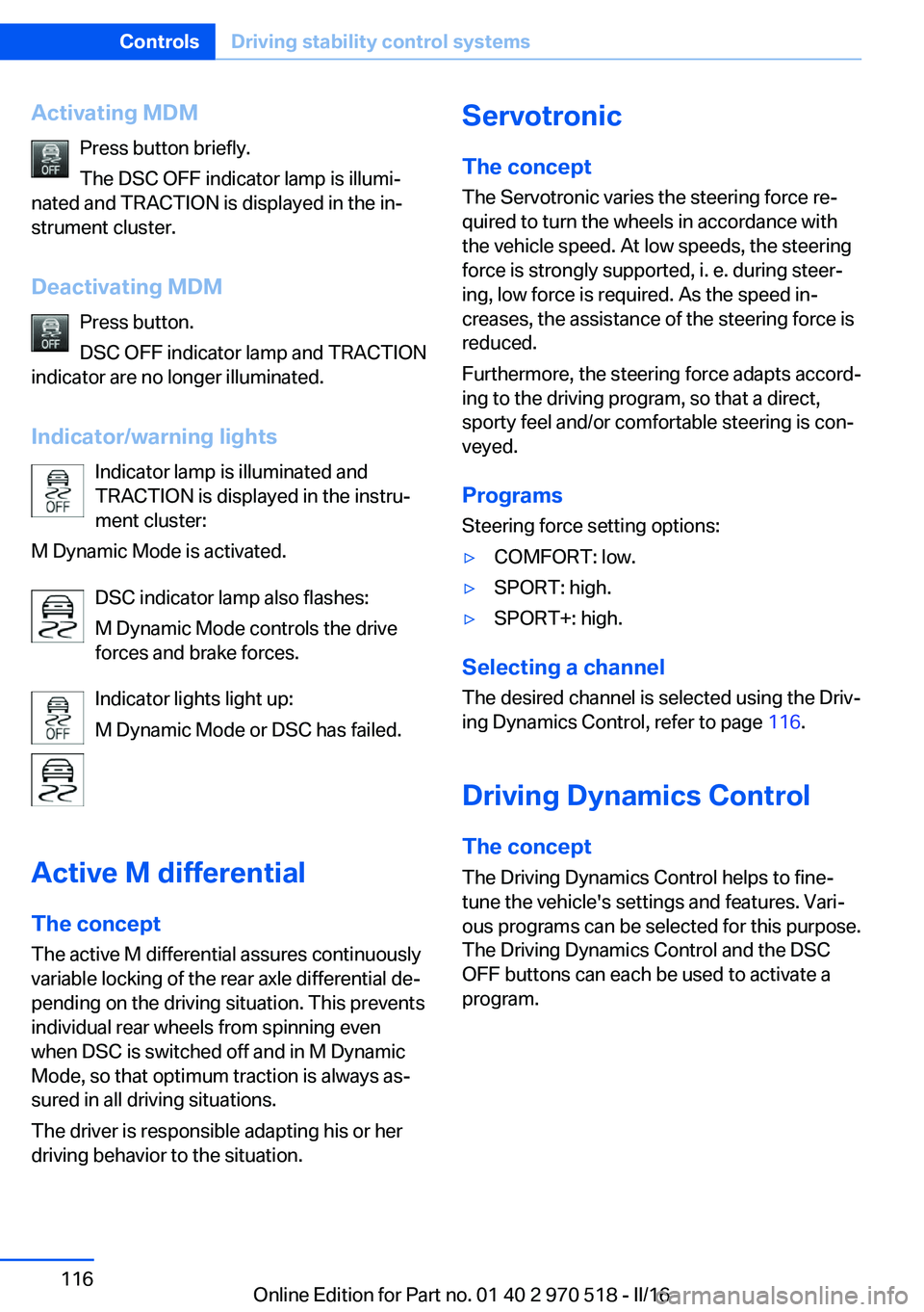
Activating MDMPress button briefly.
The DSC OFF indicator lamp is illumi‐
nated and TRACTION is displayed in the in‐
strument cluster.
Deactivating MDM Press button.
DSC OFF indicator lamp and TRACTION
indicator are no longer illuminated.
Indicator/warning lights Indicator lamp is illuminated and
TRACTION is displayed in the instru‐
ment cluster:
M Dynamic Mode is activated.
DSC indicator lamp also flashes:
M Dynamic Mode controls the drive
forces and brake forces.
Indicator lights light up:
M Dynamic Mode or DSC has failed.
Active M differential The concept The active M differential assures continuously
variable locking of the rear axle differential de‐
pending on the driving situation. This prevents individual rear wheels from spinning even
when DSC is switched off and in M Dynamic
Mode, so that optimum traction is always as‐
sured in all driving situations.
The driver is responsible adapting his or her
driving behavior to the situation.Servotronic
The concept
The Servotronic varies the steering force re‐
quired to turn the wheels in accordance with
the vehicle speed. At low speeds, the steering
force is strongly supported, i. e. during steer‐
ing, low force is required. As the speed in‐
creases, the assistance of the steering force is
reduced.
Furthermore, the steering force adapts accord‐
ing to the driving program, so that a direct,
sporty feel and/or comfortable steering is con‐
veyed.
Programs Steering force setting options:▷COMFORT: low.▷SPORT: high.▷SPORT+: high.
Selecting a channel
The desired channel is selected using the Driv‐
ing Dynamics Control, refer to page 116.
Driving Dynamics Control The conceptThe Driving Dynamics Control helps to fine-
tune the vehicle's settings and features. Vari‐
ous programs can be selected for this purpose.
The Driving Dynamics Control and the DSC
OFF buttons can each be used to activate a
program.
Seite 116ControlsDriving stability control systems116
Online Edition for Part no. 01 40 2 970 518 - II/16
Page 119 of 220
Driving comfortVehicle features and options
This chapter describes all standard, country-
specific and optional features offered with the
series. It also describes features that are not
necessarily available in your car, e. g., due to
the selected options or country versions. This
also applies to safety-related functions and
systems. The respectively applicable country
provisions must be observed when using the
respective features and systems.
Cruise control The concept Using this system, a desired speed can be ad‐
justed using the buttons on the steering wheel.
The system maintains the desired speed. The system accelerates and brakes automatically
as needed.
General information Depending on the driving settings, the features
of the cruise control can change in certain
areas.
Information WARNING
The system does not release from the
personal responsibility to correctly assess the
traffic situation. Based on the limits of the sys‐
tem, it cannot independently react to all traffic
situations. There is risk of an accident. Adjust
the driving style to the traffic conditions. Watch
traffic closely and actively intervene in the re‐
spective situations.◀
WARNING
The use of the system can lead to an in‐
creased risk of accidents in the following situa‐
tions:▷On winding roads.▷In heavy traffic.▷On slippery roads, in fog, snow or rain, or
on a loose road surface.
There is risk of accidents or risk of property
damage. Only use the system if driving at con‐
stant speed is possible.◀
WARNING
The desired speed can be incorrectly ad‐
justed or called up by mistake. There is risk of
an accident. Adjust the desired speed to the
traffic conditions. Watch traffic closely and ac‐
tively intervene in the respective situations.◀
Overview
Buttons on the steering wheel
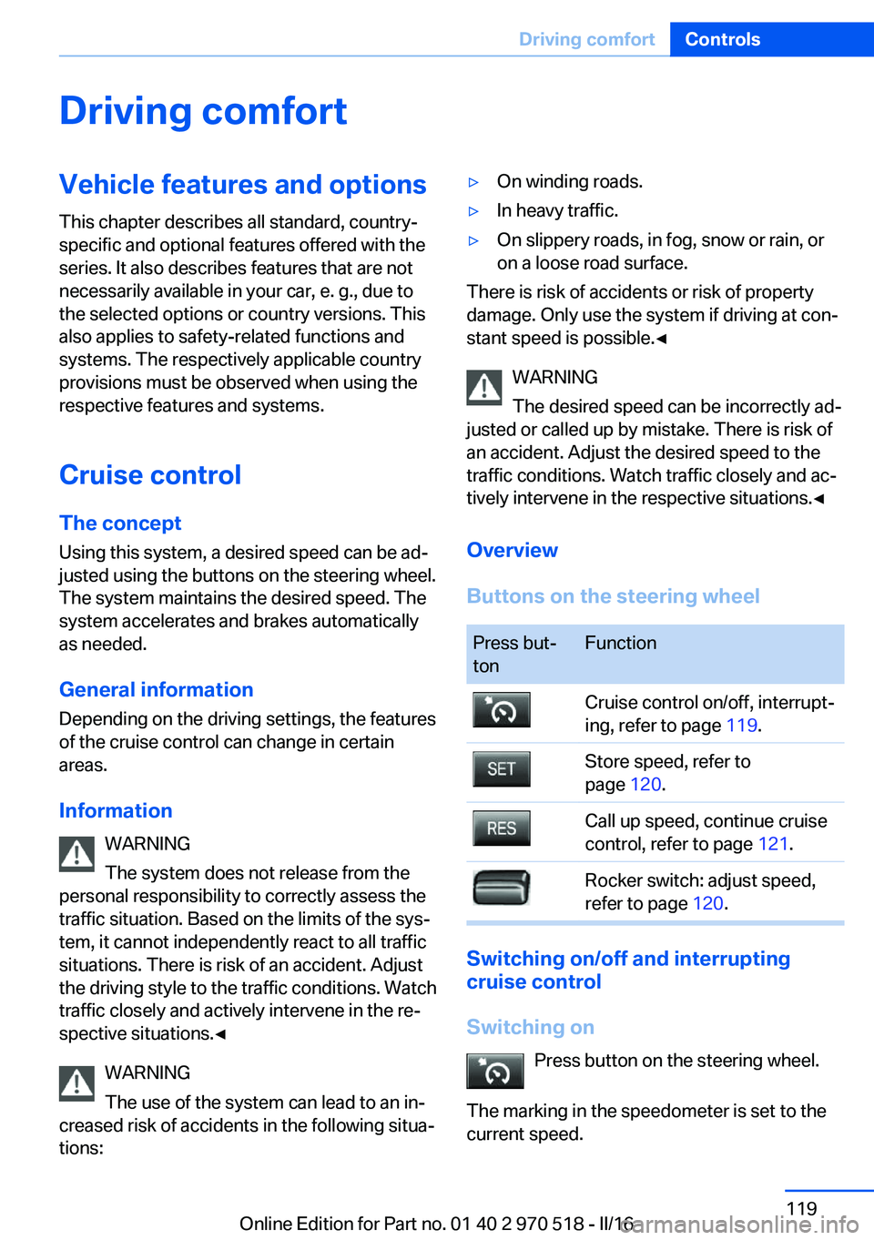
Press but‐
tonFunctionCruise control on/off, interrupt‐
ing, refer to page 119.Store speed, refer to
page 120.Call up speed, continue cruise
control, refer to page 121.Rocker switch: adjust speed,
refer to page 120.
Switching on/off and interrupting
cruise control
Switching on Press button on the steering wheel.
The marking in the speedometer is set to the
current speed.
Seite 119Driving comfortControls119
Online Edition for Part no. 01 40 2 970 518 - II/16
Page 120 of 220

Cruise control can be used.
DSC will be switched on if needed.
Switching off Press button on the steering wheel.▷If active: press twice.▷If interrupted: press once.
The displays go out. The stored desired speed
is deleted.
Interrupting manually When active, press the button on the
steering wheel.
Automatic interruption The system is automatically interrupted in the
following situations:
▷When the driver applies the brakes.▷If the clutch pedal is depressed for a few
seconds or released while a gear is not en‐
gaged.▷If the gear engaged is too high for the cur‐
rent speed.▷If MDM is activated or DSC is deactivated.▷When DSC is actively controlling stability.▷When SPORT+ is activated with Driving
Dynamics Control.Setting the speed
Maintaining/storing the speed
Press the rocker switch while the system is in‐
terrupted.
When the system is switched on, the current
speed is maintained and stored as the desired
speed.
The stored speed is displayed in the speedom‐
eter and briefly in the instrument cluster, refer
to page 121.
DSC will be switched on if needed.
The speed can also be stored by pressing a
button.
Press button.
Changing the speed
Press the rocker switch up or down repeatedly
until the desired speed is set.
If active, the displayed speed is stored and the
vehicle reaches the stored speed when the
road is clear.
Seite 120ControlsDriving comfort120
Online Edition for Part no. 01 40 2 970 518 - II/16
Page 121 of 220
▷Each time the rocker switch is pressed to
the point of resistance, the desired speed
increases or decreases by approx.
1 mph/1 km/h.▷Each time the rocker switch is pressed
past the point of resistance, the desired
speed increases or decreases by a maxi‐
mum of 5 mph/10 km/h.
The maximum speed that can be set de‐
pends on the vehicle.▷Pressing the rocker switch to the resist‐
ance point and holding it accelerates or de‐
celerates the vehicle without requiring
pressure on the accelerator pedal.
After the rocker switch is released, the ve‐
hicle maintains its final speed. Pressing the
switch beyond the resistance point causes
the vehicle to accelerate more rapidly.
Continuing cruise control
General information
An interrupted cruise control can be continued
by calling up the stored speed.
In the following cases, the stored speed value
is deleted and cannot be called up again:
▷When the system is switched off.▷When the ignition is switched off.
Information
Make sure that the difference between current
speed and stored speed is not too large before
calling up the stored speed. Otherwise, unin‐
tentional braking or accelerating may occur.
Calling up stored speed Press button on the steering wheel.
The stored speed is reached and maintained.
Displays in the instrument cluster
Indicator lamp Depending on how the vehicle is equip‐
ped, the indicator lamp in the instru‐
ment cluster indicates whether the sys‐
tem is switched on.
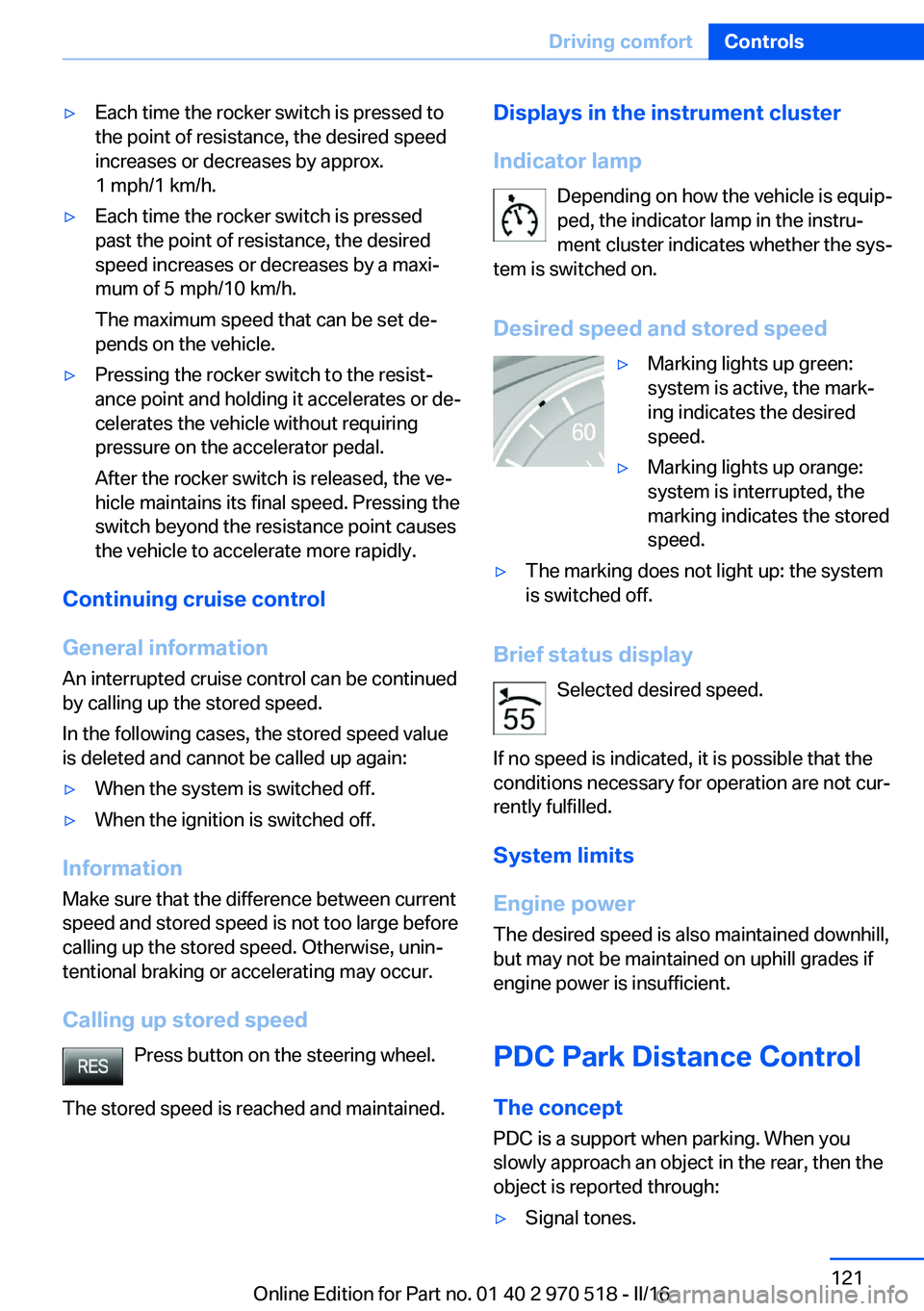
Desired speed and stored speed▷Marking lights up green:
system is active, the mark‐
ing indicates the desired
speed.▷Marking lights up orange:
system is interrupted, the
marking indicates the stored
speed.▷The marking does not light up: the system
is switched off.
Brief status display
Selected desired speed.
If no speed is indicated, it is possible that the
conditions necessary for operation are not cur‐
rently fulfilled.
System limits
Engine power The desired speed is also maintained downhill,
but may not be maintained on uphill grades if
engine power is insufficient.
PDC Park Distance Control The concept
PDC is a support when parking. When you
slowly approach an object in the rear, then the
object is reported through:
▷Signal tones.Seite 121Driving comfortControls121
Online Edition for Part no. 01 40 2 970 518 - II/16
Page 125 of 220
▷Keep the recording range of the camera
clear. Protruding cargo can lead to mal‐
functions.
Activating assistance functions
More than one assistance function can be ac‐
tive at the same time.
▷Parking aid lines
"Parking aid lines"
Lanes and turning radius are indicated.
▷Obstacle marking
"Obstacle marking"
Spatially-shaped markings are displayed.
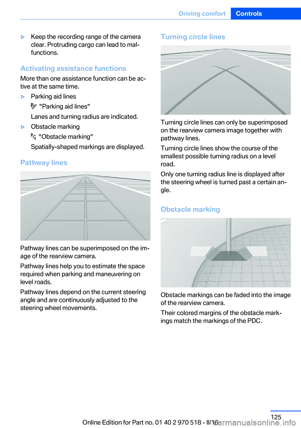
Pathway lines
Pathway lines can be superimposed on the im‐
age of the rearview camera.
Pathway lines help you to estimate the space
required when parking and maneuvering on
level roads.
Pathway lines depend on the current steering
angle and are continuously adjusted to the
steering wheel movements.
Turning circle lines
Turning circle lines can only be superimposed
on the rearview camera image together with
pathway lines.
Turning circle lines show the course of the
smallest possible turning radius on a level
road.
Only one turning radius line is displayed after
the steering wheel is turned past a certain an‐
gle.
Obstacle marking
Obstacle markings can be faded into the image
of the rearview camera.
Their colored margins of the obstacle mark‐
ings match the markings of the PDC.
Seite 125Driving comfortControls125
Online Edition for Part no. 01 40 2 970 518 - II/16
Page 126 of 220
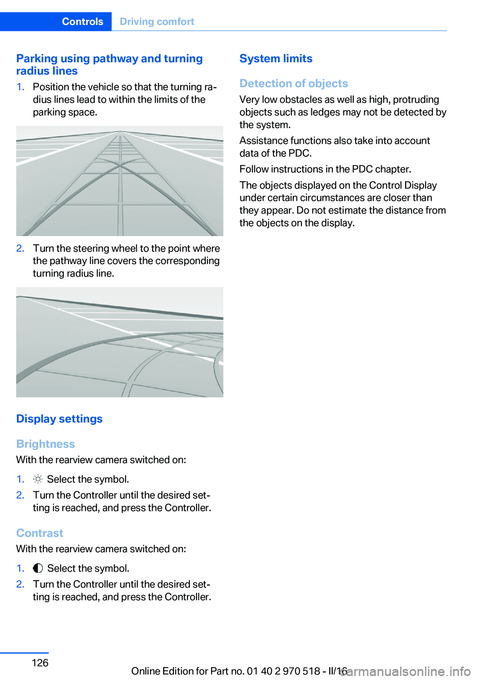
Parking using pathway and turning
radius lines1.Position the vehicle so that the turning ra‐
dius lines lead to within the limits of the
parking space.2.Turn the steering wheel to the point where
the pathway line covers the corresponding
turning radius line.
Display settings
Brightness
With the rearview camera switched on:
1. Select the symbol.2.Turn the Controller until the desired set‐
ting is reached, and press the Controller.
Contrast
With the rearview camera switched on:
1. Select the symbol.2.Turn the Controller until the desired set‐
ting is reached, and press the Controller.System limits
Detection of objects
Very low obstacles as well as high, protruding
objects such as ledges may not be detected by
the system.
Assistance functions also take into account
data of the PDC.
Follow instructions in the PDC chapter.
The objects displayed on the Control Display
under certain circumstances are closer than
they appear. Do not estimate the distance from
the objects on the display.Seite 126ControlsDriving comfort126
Online Edition for Part no. 01 40 2 970 518 - II/16
Page 168 of 220

Wheels and tiresVehicle features and options
This chapter describes all standard, country-
specific and optional features offered with the
series. It also describes features that are not
necessarily available in your car, e. g., due to
the selected options or country versions. This
also applies to safety-related functions and
systems. The respectively applicable country
provisions must be observed when using the
respective features and systems.
Tire inflation pressure Safety information
The tire characteristics and tire inflation pres‐
sure influence the following:▷The service life of the tires.▷Road safety.▷Driving comfort.
Checking the tire inflation pressure
WARNING
A tire with low or missing tire inflation
pressure impacts handling, such as steering
and braking response. There is risk of an acci‐
dent. Regularly check the tire inflation pres‐
sure, and correct it as needed, e.g., twice a
month and before a long trip.◀
Tires have a natural, consistent loss of tire in‐
flation pressure.
Tires heat up while driving, and the tire infla‐
tion pressure increases along with the tire's
temperature. The tire inflation pressure speci‐
fications relate to cold tires or tires with the
ambient temperature.
Only check the tire inflation pressure when the
tires are cold. This means after driving no more
than 1.25 miles/2 km or when the vehicle has
been parked for at least 2 hours.
The displays of inflation devices may under-
read by up to 0.1 bar/2 psi.
For Flat Tire Monitor: after correcting the tire
inflation pressure, reinitialize the Flat Tire
Monitor.
For Tire Pressure Monitor: after correcting the
tire inflation pressure, reset the Tire Pressure
Monitor.
Tire inflation pressure specifications
The tire inflation pressure table, refer to
page 169, contains all tire inflation pressure
specifications for the specified tire sizes at the
ambient temperature. The tire inflation pres‐
sure values apply to tire sizes approved by the
manufacturer of the vehicle for the vehicle
type.
To identify the correct tire inflation pressure,
please note the following:▷Tire sizes of your vehicle.▷Maximum permitted driving speed.
Tire inflation pressures up to
100 mph/160 km/h
For speeds of up to 100 mph/160 km/h and for
optimum driving comfort, note the pressure
values in the tire inflation pressure table, refer
to page 169, and adjust as necessary.
Seite 168MobilityWheels and tires168
Online Edition for Part no. 01 40 2 970 518 - II/16
Page 173 of 220
Do not exceed the maximum tire inflation pres‐
sure indicated on the side wall of the tire.
Repairing a flat tire
Safety measures▷Park the vehicle as far away as possible
from passing traffic and on solid ground.▷Switch on the hazard warning system.▷Secure the vehicle against rolling away by
setting the parking brake.▷Turn the steering wheel until the front
wheels are in the straight-ahead position
and engage the steering wheel lock.▷Have all vehicle occupants get out of the
vehicle and ensure that they remain out‐
side the immediate area in a safe place,
such as behind a guardrail.▷If necessary, set up a warning triangle at an
appropriate distance.
Mobility System
The concept
With the Mobility System, minor tire damage
can be sealed temporarily to enable continued
travel. To accomplish this, sealant is pumped
into the tires, which seals the damage from the
inside.
The compressor can be used to check the tire
inflation pressure.
Information
▷Follow the instructions on using the Mobi‐
lity System found on the compressor and
sealant container.▷Use of the Mobility System may be ineffec‐
tive if the tire puncture measures approx.
1/8 in/4 mm or more.▷Contact a dealer’s service center or an‐
other qualified service center or repair
shop if the tire cannot be made drivable.▷If possible, do not remove foreign bodies
that have penetrated the tire.▷Pull the speed limit sticker off the sealant
container and apply it to the steering
wheel.▷The use of a sealant can damage the TPM
wheel electronics. In this case, have the
electronics checked at the next opportu‐
nity and have them replaced if needed.
DANGER
If the exhaust pipe is blocked or ventila‐
tion is insufficient, harmful exhaust gases can
enter into the vehicle. The exhaust gases con‐
tain carbon monoxide, an odorless and color‐
less but highly toxic gas. In enclosed areas, ex‐
haust gases can also accumulate outside of
the vehicle. There is danger to life. Keep the
exhaust pipe free and ensure sufficient ventila‐
tion.◀
Storage
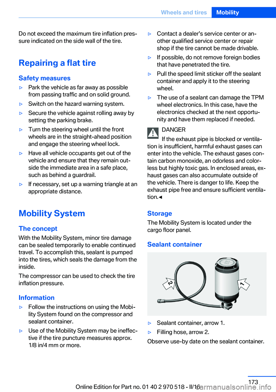
The Mobility System is located under the cargo floor panel.
Sealant container
▷Sealant container, arrow 1.▷Filling hose, arrow 2.
Observe use-by date on the sealant container.
Seite 173Wheels and tiresMobility173
Online Edition for Part no. 01 40 2 970 518 - II/16