2016 AUDI RS7 SPORTBACK trailer
[x] Cancel search: trailerPage 109 of 282

Parking systems
General information
Applies to: vehicl es with parking system plus/rear view cam
era/peripheral cameras
Depending on your vehicle's equipment, various
parking aids will help you when parking and ma
neuvering.
The
parking system plus assists you when park
ing by audibly and visually indicating objects de
tected
in front of and behind the vehicle
¢page 108.
The rear view camera shows the area behind the
vehicle in the Infotainment display. This display
assists you when you are cross or parallel parking
¢ page 109. In addition, you are assisted by the
functions from the parking system plus
¢ page 108.
The peripheral cameras assist you with parking
and maneuvering. You are aided by various cam
e ras depending on the vehicle equipment leve l
¢page 112. In addition, you are assisted by the
functions from the parking system plus
¢page 108.
A WARNING
-Always look for traffic and check the area
around your vehicle by looking at it directly
as well. The parking system cannot replace
the driver's attention. The driver is always
responsible for safety during parking and
for all other maneuvers.
-
-Please note that some surfaces, such as
clothing, are not detected by the system.
- Sensors and cameras have blind spots in
which people and objects cannot be detect ed. Be especially cautious of children and
animals.
- The sensors can be displaced by impacts or
damage to the radiator grille, bumper,
wheel housing and the underbody. The park
ing systems may become impaired as a re
sult. Have your authorized Audi dealer or
qualified workshop check their function.
- Make sure the sensors are not covered by
stickers, deposits or any other obstructions
Parking systems
as it may impair the sensor function. For in
formation on cleaning, refer to
¢page 193.
(D Note
-Some objects are not detected by the sys
tem under certain circumstances:
- Objects such as barrier chains, trailer draw
bars, vertical poles or fences
- Objects above the sensors such as wall ex tensions
- Objects with specific surfaces or struc
tures such as chain link fences or powder
snow.
- If you continue driving closer to a low-lying
object, it may disappear from the sensor
range . Note that you will no longer be
warned about this obstacle.
(D Tips
- The system may provide a warning even
though there are no obstacles in the cover age area in some situations, such as:
- certain road surfaces or for long grass.
- external ultrasonic sources e.g. from cleaning vehicles.
- heavy rain, snow or thick vehicle exhaust.
- We recommend that you practice parking in
a traffic-free location or parking lot to be
come familiar with the system. When doing
this, there should be good light and weath
er conditions.
- You can change the volume and pitch of the
signals as well as the display
¢page 116.
- What appears in the infotainment display is
somewhat time-delayed.
107
Page 112 of 282

Parking systems
-The camera lens enlarges and distorts the
field of vision. The object appears both al
tered and inaccurate on the screen.
- In certain situations, people or objects in
the display appear closer or farther away:
- For objects that do not touch the ground,
such as the bumper of a parked vehicle, a
trailer hitch or the rear of a truck. Do not
use the help lines in this case.
- If driven from a level surface onto an in
cline, or a downward slope.
- If driven toward protruding objects.
- If the vehicle is carrying too much load in
the rear.
(D Note
- Always read and follow the applicable warn
ings r::!>(D
in General information on
page 107 .
-The orange colored orientation lines in the
Infotainment display show the vehicle path
depending on the steering wheel angle. The
front of the vehicle swings out more than
the rear of the vehicle. Maintain plenty of
distance so that your outside mirror or a
corner of your vehicle does not collide with
any obstacles.
Switching on/off
Applies to: vehicles with rearview camera
Switching on
.,. Shift into reverse, or
.,. Press the
P,,, A button in the center console
r:=> page 108, fig. 120. A short confirmation
tone sounds and the LED in the button turns
on.
Switching between the rearview camera and
optical display
.,. Press the Graphic control button ®
r:=> page 110, fig. 125 to see the optical display .
.,. Press the
Rear view control button to see the
. . rearv1ew camera image.
Switching off
.,. Drive forward faster than 10 km/h, or
.,. press the
P,1
1.A button, or
110
.,. Switch the ignition off.
@ Tips
- The visual display in the left part of the dis
play should help you detect the critical vehi
cle areas.
- You can change the volume and pitch of the
signals as well as the display
r:=> page 116.
Cross parking
Applies to: vehicles with rearview camera
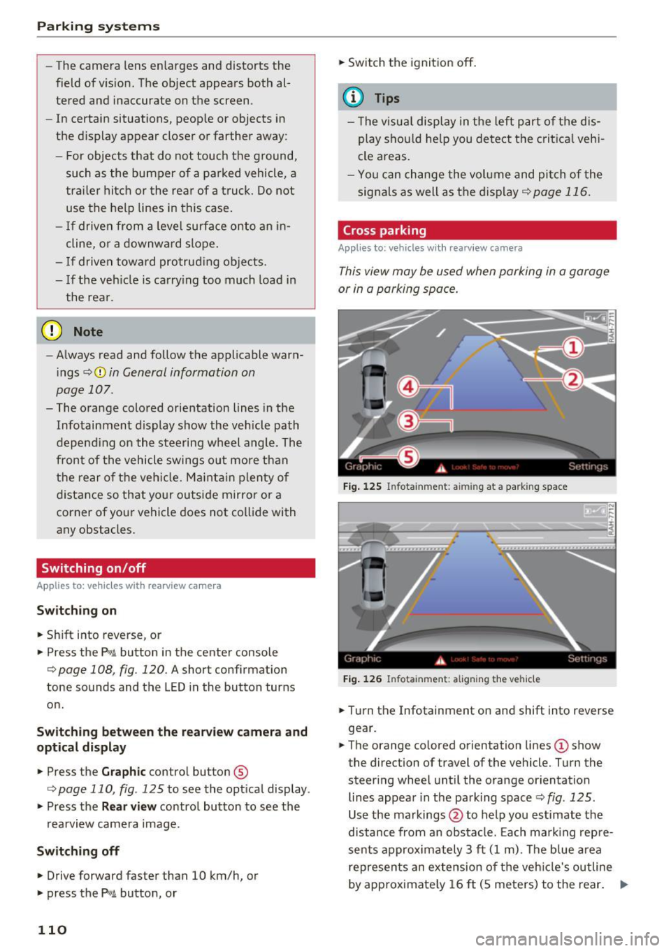
This view may be used when parking in a garage
or in a parking space.
Fig. 125 Infotainment: aiming at a parking space
Fig. 126 Infota inment: aligning the vehicle
.,. Turn the Infotainment on and shift into reverse
gear.
.,. The orange colored orientation lines
(D show
the direction of travel of the vehicle. Turn the
steer ing wheel until the orange orientation
lines appear in the parking space r::!>
fig. 125 .
Use the markings @to help you estimate the
distance from an obstacle. Each marking repre
sents approximately 3 ft
(1 m). The blue area
represents an extension of the vehicle's outline
by approximately
16 ft (5 meters) to the rear. ..,.
Page 232 of 282

Wheels
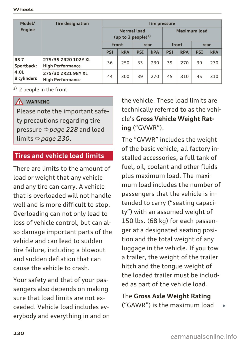
Model/ Tire designation Tire pressure
Engine Normal load Maximum load
(up to 2 people)a>
front rear front rear
PSI
RS 7 275/35 ZR20 102Y XL
Sportback: High Performance
36
4.0L 275/30 ZR21 98Y XL
8 cylinders High Performance
44
a) 2 people in the front
A WARNING
Please note the important safe
ty precautions regarding tire
pressure ¢
page 228 and load
limits ¢
page 230.
Tires and vehicle load limits
There are limits to the amount of
load or weight that any vehicle
and any tire can carry. A vehicle
that is overloaded will not handle
well and is more difficult to stop. Overloading can not only lead to
loss of vehicle control, but can al
so damage important parts of the
vehicle and can lead to sudden
tire failure, including a blowout and sudden deflation that can
cause the vehicle to crash.
Your safety and that of your pas sengers also depends on making
sure that load limits are not ex
ceeded . Vehicle load includes ev
erybody and everything in and on
230
kPA PSI kPA PSI kPA PSI kPA
25 0 33 230 39 270
39 270
30 0 39 270 45 310 45
310
the vehicle. These load limits are
technically referred to as the vehi
cle's
Gross Vehicle Weight Rat
ing
("GVWR").
The "GVWR" includes the weight of the basic vehicle, all factory in
stalled accessories , a full tank of
fuel, oil, coolant and other fluids
plus maximum load. The maxi
mum load includes the number of
passengers that the vehicle is in
tended to carry ("seating capaci
ty") with an assumed weight of 150 lbs. (68 kg) for each passen
ger at a designated seating posi
tion and the total weight of any luggage in the vehicle. If you tow
a trailer, the weight of the trailer hitch and the tongue weight of
the loaded trailer must be includ ed as part of the vehicle load.
The
Gross Axle Weight Rating
("GAWR") is the maximum load
Page 233 of 282

that can be applied at each of the
vehicle's two axles.
The fact that there is an upper
limit to your vehicle 's Gross Vehi
cle Weight Rating means that the
total weight of whatever is being carried in the vehicle (including
the weight of a trailer hitch and
the tongue weight of the loaded
trailer) is limited. The more pas sengers in the vehicle or passen
gers who are heavier than the
standard weights assumed mean
that less weight can be carried as luggage.
The Gross Vehicle Weight Rating and the Gross Axle Weight Rating
are listed on the safety compli
ance sticker label located on the
driver 's side 8-pillar
¢ page 228,
fig. 192.
& WARNING
-
Overloading a vehicle can cause
loss of vehicle control, a crash
or other accident, serious per
sonal injury, and even death.
-Carrying more weight than
your vehicle was designed to carry will prevent the vehicle
from handling properly and increase the risk of the loss of
vehicle control.
Wheels
-The brakes on a vehicle that
has been overloaded may not
be able to stop the vehicle
within a safe distance.
-Tires on a vehicle that has
been overloaded can fail sud
denly, including a blowout and
sudden deflation, causing loss
of control and a crash.
-Always make sure that the to
tal load being transported -
including the weight of a trail
er hitch and the tongue
weight of a loaded trailer - does not make the vehicle
heavier than the vehicle's
Gross Vehicle Weight Rating.
Determining correct load
limit
Use the example below to calcu
late the total weight of the pas
sengers and luggage or other
things that you plan to transport
so that you can make sure that
your vehicle will not be overload ed.
Steps for Determining Correct Load Limit
1. Locate the statement "THE
COMBINED WEIGHT OF OCCU-
PANTS AND CARGO SHOULD .,.
231
Page 234 of 282

Wheels
NEVER EXCEED XXX KG OR XXX
LBS"on your vehicle's placard
(tire inflation pressure label)
¢page 228, fig. 192.
2. Determine the combined
weight of the driver and pas
sengers that will be riding in
your vehicle.
3. Subtract the combined weight
of the driver and passengers
from
"XXX" kilograms or "XXX"
pounds shown on the sticker
¢ page 228, fig. 192.
4. The resulting figure equals the
available amount of cargo and
luggage load capacity. For ex
ample, if the "XXX" amount
equals 1400 lbs. and there will
be five 150 lbs. passengers in
your vehicle, the amount of available cargo and luggage
load capacity is 650 lbs.
(1400-750 (5 X 150) = 650
lbs.)
5. Determine the combined
weight of luggage and cargo being loaded on the vehicle.
That weight may not safely ex ceed the available cargo and
luggage load capacity calculat
ed in Step 4.
6. If your vehicle will be towing a trailer, load from your trailer
232
will be transferred to your ve
hicle. Consult this manual to
determine how this reduces
the available cargo and lug
gage load capacity of your vehi
cle.
~check the tire sidewall
(¢page 218, fig. 190) to deter
mine the designated load rating
for a specific tire.
Wheel bolts and rims '
Wheel bolts
Wheel bolts must be clean and loosen/tighten
easily.
Rims
Rims with a bolted rim ring* or with bolted wheel
covers* consist of multiple pieces. These compo
nents were bolted together using special bolts
and a special procedure . You must not repair or
disassemble them
9 &. .
_&. WARNING
Wheel bolts that are tightened or repaired in
correctly can become loose and result in loss
of vehicle control, which increases the risk of
an accident. For the correct tightening specifi
cation, refer to
9 page 244, After changing a
wheel .
-Always keep the wheel bolts and the
threads in the wheel hub clean and free of
grease .
- Only use wheel bolts that fit the rim.
- Always have damaged rims repaired by an
authorized Audi dealer or authorized Audi
Service Facility. Never repair or disassemble
rims yourself, because this increases the risk
of an accident.
Page 252 of 282

Fuses
Driver side cockpit fuse
assignment
Fig . 209 Driver side cockp it: fuse panel with plastic bracket
Fuse panel @ (black)
No . Equipment
Electromechanical power steering, trailer
1 hitch, ionizer, switch strip, seat heating
(rear), electromechanical parking brake
Horn, climate control system, Gateway,
2 automatic dimming interior rearv iew mir·
ror
4 Park ing aid, headlight range adjustment
5 Dynamic steering, Electron
ic Stabilization
Control (ESC)
6 Headlights
7 Adaptive cruise control
8 Front passenger's seat sensors, airbag
9 Gateway
10 Engine sound, night vision
assist, garage
door opener (Home Link), parking aid
11 Video camera
image processing
12 Headlights
13 Steering column switch module
14 Terminal 15 (luggage compartment)
250
Fuse panel
@ (black)
15 Terminal 15 (engine compartment)
16 Starter
Fuse panel @ (brown)
No. Equipment
1 Infotainment
2 Infotainment
3 F
ron t passenger's seat
5 Airbag, Elect
ronic Stabilization Control
(ESC)
6 Anti·theft alarm system
7 Electromechanical parking brake
8 Inter ior lights
9
Windshield video camera heating, light/
rain sensor
10 Lumbar support (driver's seat)
11 Driver's seat
12 Electronic stabilization control
13 Horn
14 Headlights
15 Front
seat heating
16 Dynamic steering
Fuse panel © (red)
No . Equipment
1 Clutch pedal
2 Fuel pump
3 Brake light sensor
4 AdBlue (diesel
engine)/engine acoustics
5 Rear door
6 Front
door
7 Electronic stab ilizat ion control
8 Windshield wiper motor
9 Headlight washer system
10 Interior
lighting, climate control system
11 Headlights
12 Sunroof