Page 33 of 112

INSTRUMENT AND CONTROL FUNCTIONS
3-18
3
3. Wipe up any spilled fuel immedi- ately. NOTICE: Immediately
wipe off spille d fuel with a clean,
d ry, soft cloth, since fuel may
d eteriorate painte d surfaces or
plastic parts.
[ECA10072]
4. Be sure to securely close the fuel tank cap.
WARNING
EWA15152
Gasoline is poisonous an d can
cause injury or d eath. Handle gaso-
line with care. Never siphon gasoline
b y mouth. If you shoul d swallow
some gasoline or inhale a lot of gas-
oline vapor, or get some g asoline in
your eyes, see your doctor imme di- ately. If g
asoline spills on your skin,
wash with soap an d water. If gaso-
line spills on your clothin g, chan ge
your clothes.
EAU54601
NOTICE
ECA11401
Use only unlea ded g asoline. The use
of lead ed g asoline will cause severe
d amag e to internal en gine parts,
such as the valves an d piston rin gs,
as well as to the exhaust system.Your Yamaha engine has been de-
signed to use premium unleaded gas-
oline with a research octane number of
95 or higher. If knocking (or pinging)
occurs, use a gasoline of a different brand. Use of unleaded fuel will extend
spark plug life and reduce mainte-
nance costs.
Gasohol
There are two types of gasohol: gaso-
hol containing ethanol and that con-
taining methanol. Gasohol containing
ethanol can be used if the ethanol con-
tent does not exceed 10% (E10). Gas-
ohol containing methanol is not
recommended by Yamaha because it
can cause damage to the fuel system
or vehicle performance problems.
1. Fuel tank filler tube
2. Maximum fuel level
2
1
Recommen ded fuel:
Premium unleaded gasoline (Gaso-
hol (E10) acceptable)
Fuel tank capacity:
17.3 L (4.57 US gal, 3.81 Imp.gal)
Fuel reserve amount (when the fuel
level warnin g li ght comes on):
3.5 L (0.92 US gal, 0.77 Imp.gal)
U2CXE1E0.book Page 18 Friday, July 25, 2014 11:05 AM
Page 34 of 112

INSTRUMENT AND CONTROL FUNCTIONS
3-19
3
EAU58081
Fuel tank breather hose an d
overflow hoseBefore operating the motorcycle:
Check each hose connection.
Check each hose for cracks or
damage, and replace if necessary.
Make sure that the end of each
hose is not blocked, and clean if
necessary.
Make sure that the end of each
hose is positioned outside of the
cowling.
Make sure that each hose is rout-
ed through the clamp or guide.
EAU13446
Catalytic convertersThis vehicle is equipped with catalytic
converters in the exhaust system.
WARNING
EWA10863
The exhaust system is hot after op-
eration. To prevent a fire hazar d or
b urns:
Do not park the vehicle near
possi ble fire hazard s such as
g rass or other materials that
easily burn.
Park the vehicle in a place
where ped estrians or chil dren
are not likely to touch the hot
exhaust system.
Make sure that the exhaust sys-
tem has coole d down before
d oin g any maintenance work.
Do not allow the en gine to i dle
more than a few minutes. Lon g
i d lin g can cause a b uild-up of
heat.
NOTICE
ECA10702
Use only unlea ded g asoline. The use
of lead ed g asoline will cause unre-
pairab le damag e to the catalytic
converter.
1. Guide
2. Fuel tank breather hose and overflow hose
2
1
U2CXE1E0.book Page 19 Friday, July 25, 2014 11:05 AM
Page 35 of 112
INSTRUMENT AND CONTROL FUNCTIONS
3-20
3
EAU39034
SeatsRider seat
To remove the rider seatPull back the rear of the rider seat as
shown, remove the bolts, and then pull
the seat off.
To install the rider seatInsert the projection on the front of the
rider seat into the seat holder as
shown, place the seat in the original
position, and then install the bolts. Passen
ger seat
To remove the passenger seat
1. Insert the key into the seat lock, and then turn it clockwise. 2. While holding the key in that posi-
tion, lift the front of the passenger
seat and pull it forward.
To install the passenger seat
1. Insert the projections on the pas- senger seat into the seat holders
as shown, and then push the front
of the seat down to lock it in place.
2. Remove the key.TIPMake sure that the seats are properly
secured before riding.
1. Bolt
1. Projection
2. Seat holder
1. Seat lock
2. Unlock.
1. Projection
2. Seat holder
U2CXE1E0.book Page 20 Friday, July 25, 2014 11:05 AM
Page 36 of 112

INSTRUMENT AND CONTROL FUNCTIONS
3-21
3
EAU39074
Helmet holdin g ca bleA helmet holding cable is provided in
the owner’s tool kit to secure two hel-
mets to the helmet cable holder
equipped on the bottom of the passen-
ger seat.
To secure a helmet with the helmet
hol din g cab le
1. Remove the passenger seat. (See page 3-20.)
2. Clip the middle snap hook of the cable onto the cable holder. 3. Pass one of the other snap hooks
of the cable through the helmet
strap buckle, and then clip the
snap hook onto the cable holder
as shown.
4. Install the passenger seat. WARNING! Never ri de with a
helmet attached to a helmet
hol din g cab le, since the helmet
may hit o bjects, causin g loss of
control an d possi bly an acci-
d ent.
[EWA14332]
To release a helmet from the helmet
hol din g cab le
1. Remove the passenger seat.
2. Unfasten the snap hooks from the cable holder, and then remove the
cable from the helmet strap buck-
le.
3. Install the passenger seat.
1. Helmet holding cable
2. Helmet cable holder
3. Middle snap hook
1. Snap hook
2. Helmet holding cable
3. Helmet
1
2
3
1. Helmet holding cable
2. Helmet
U2CXE1E0.book Page 21 Friday, July 25, 2014 11:05 AM
Page 37 of 112

INSTRUMENT AND CONTROL FUNCTIONS
3-22
3
EAU39672
Rear view mirrorsThe rear view mirrors of this vehicle
can be folded forward or backward for
parking in narrow spaces. Fold the mir-
rors back to their original position be-
fore riding.
WARNING
EWA14372
Be sure to fold the rear view mirrors
b ack to their ori ginal position before
ri din g.
EAU38946
A djustin g the front fork
WARNING
EWA10181
Always a djust both fork le gs equally,
otherwise poor han dlin g an d loss of
sta bility may result.This front fork is equipped with spring
preload adjusting bolts, rebound
damping force adjusting screws, com-
pression damping force adjusting bolts
(for fast compression damping) and
compression damping force adjusting
bolts (for slow compression damping).NOTICE
ECA10102
To avoi d d amag ing the mechanism,
d o not attempt to turn b eyond the
maximum or minimum settin gs.Sprin g preloa d
To increase the spring preload and
thereby harden the suspension, turn
the adjusting bolt on each fork leg in di-
rection (a). To decrease the spring pre-
load and thereby soften the
suspension, turn the adjusting bolt on
each fork leg in direction (b). Align the appropriate groove on the ad-
justing mechanism with the top of the
front fork collar.
1. Riding position
2. Parking position
2
2
1
2
2
1
1. Spring preload adjusting bolt
1. Current setting
2. Front fork collar1
(a) (b)
U2CXE1E0.book Page 22 Friday, July 25, 2014 11:05 AM
Page 38 of 112
")
INSTRUMENT AND CONTROL FUNCTIONS
3-23
3Reboun d d ampin g force
To increase the rebound damping
force and thereby harden the rebound
damping, turn the adjusting screw on
each fork leg in direction (a). To de-
crease the rebound damping force and
thereby soften the rebound damping,
turn the adjusting screw on each fork
leg in direction (b). Compression
dampin g force
To adjust the compression damping
force (for fast compression damping)To increase the compression damping
force and thereby harden the com-
pression damping, turn the adjusting
bolt on each fork leg in direction (a). To
decrease the compression damping
force and thereby soften the compres-
sion damping, turn the adjusting bolt
on each fork leg in direction (b). To adjust the compression damping
force (for slow compression damping)To increase the compression damping
force and thereby harden the com-
pression damping, turn the adjusting
bolt on each fork leg in direction (a). To
decrease the compression damping
Spring preloa d setting :
Minimum (soft):
0
Standard:
2
Maximum (hard): 51. Rebound damping force adjusting screw1
(a) (b)
Re
boun d d ampin g setting :
Minimum (soft):
25 click(s) in direction (b)*
Standard:
20 click(s) in direction (b)*
Maximum (hard): 1 click(s) in direction (b)*
* With the adjusting screw fully turned in direction (a)
1. Compression damping force adjusting bolt
(for fast compression damping)Compression dampin g settin g (for
fast compression dampin g):
Minimum (soft):
4 turn(s) in direction (b)*
Standard: 2 turn(s) in direction (b)*
Maximum (hard): 0 turn(s) in direction (b)*
* With the adjusting bolt fully turned
in direction (a)
1
(a)
(b)
U2CXE1E0.book Page 23 Friday, July 25, 2014 11:05 AM
Page 39 of 112
.
TIPAlthough the total number of clicks or
turns o")
INSTRUMENT AND CONTROL FUNCTIONS
3-24
3
force and thereby soften the compres-
sion damping, turn the adjusting bolt
on each fork leg in direction (b).
TIPAlthough the total number of clicks or
turns of a damping force adjusting
mechanism may not exactly match the above specifications due to small dif-
ferences in production, the actual
number of clicks or turns always repre-
sents the entire adjusting range. To ob-
tain a precise adjustment, it would be
advisable to check the number of
clicks or turns of each damping force
adjusting mechanism and to modify
the specifications as necessary.
EAU42947
A
djustin g the shock a bsor ber
assem blyThis shock absorber assembly is
equipped with a spring preload adjust-
ing ring, a rebound damping force ad-
justing screw, a compression damping
force adjusting bolt (for fast compres-
sion damping) and a compression
damping force adjusting bolt (for slow
compression damping).NOTICE
ECA10102
To avoi d d amag ing the mechanism,
d o not attempt to turn beyon d the
maximum or minimum settin gs.Sprin g preloa d
To increase the spring preload and
thereby harden the suspension, turn
the adjusting ring in direction (a). To
decrease the spring preload and there-
by soften the suspension, turn the ad-
justing ring in direction (b). Align the appropriate notch in the
adjusting ring with the position in-
dicator on the shock absorber.
1. Compression damping force adjusting bolt
(for slow compression damping)Compression dampin g setting (for
slow compression dampin g):
Minimum (soft):
20 click(s) in direction (b)*
Standard: 15 click(s) in direction (b)*
Maximum (hard): 1 click(s) in direction (b)*
* With the adjusting bolt fully turned
in direction (a)
1
(a)
(b)
U2CXE1E0.book Page 24 Friday, July 25, 2014 11:05 AM
Page 40 of 112

INSTRUMENT AND CONTROL FUNCTIONS
3-25
3
Use the special wrench and the
extension bar included in the own-
er’s tool kit to make the adjust-
ment. Re
boun d d ampin g force
To increase the rebound damping
force and thereby harden the rebound
damping, turn the adjusting screw in
direction (a). To decrease the rebound
damping force and thereby soften the
rebound damping, turn the adjusting
screw in direction (b). Compression
dampin g force
Compression damping force (for fast
compression damping)To increase the compression damping
force and thereby harden the com-
pression damping, turn the adjusting
bolt in direction (a). To decrease the
compression damping force and there-
by soften the compression damping,
turn the adjusting bolt in direction (b).
1. Spring preload adjusting ring
2. Position indicator
3. Extension bar
4. Special wrenchSprin g preloa d setting :
Minimum (soft): 1
Standard: 4
Maximum (hard):
9
1
4
32
1. Rebound damping force adjusting screwRe boun d d ampin g setting :
Minimum (soft): 20 click(s) in direction (b)*
Standard: 16 click(s) in direction (b)*
Maximum (hard):
3 click(s) in direction (b)*
* With the adjusting screw fully turned in direction (a)
1. Compression damping force adjusting bolt
(for fast compression damping)
1
(a)
(b)
U2CXE1E0.book Page 25 Friday, July 25, 2014 11:05 AM
 1
1 2
2 3
3 4
4 5
5 6
6 7
7 8
8 9
9 10
10 11
11 12
12 13
13 14
14 15
15 16
16 17
17 18
18 19
19 20
20 21
21 22
22 23
23 24
24 25
25 26
26 27
27 28
28 29
29 30
30 31
31 32
32 33
33 34
34 35
35 36
36 37
37 38
38 39
39 40
40 41
41 42
42 43
43 44
44 45
45 46
46 47
47 48
48 49
49 50
50 51
51 52
52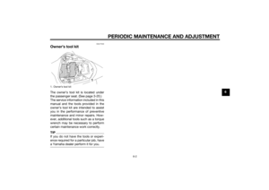 53
53 54
54 55
55 56
56 57
57 58
58 59
59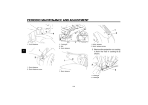 60
60 61
61 62
62 63
63 64
64 65
65 66
66 67
67 68
68 69
69 70
70 71
71 72
72 73
73 74
74 75
75 76
76 77
77 78
78 79
79 80
80 81
81 82
82 83
83 84
84 85
85 86
86 87
87 88
88 89
89 90
90 91
91 92
92 93
93 94
94 95
95 96
96 97
97 98
98 99
99 100
100 101
101 102
102 103
103 104
104 105
105 106
106 107
107 108
108 109
109 110
110 111
111