Page 81 of 112

PERIODIC MAINTENANCE AND ADJUSTMENT
6-30
6
EAU23115
Checking an d lu bricatin g the
throttle grip an d ca bleThe operation of the throttle grip
should be checked before each ride. In
addition, the cable should be lubricat-
ed by a Yamaha dealer at the intervals
specified in the periodic maintenance
chart.
The throttle cable is equipped with a
rubber cover. Make sure that the cover
is securely installed. Even though the
cover is installed correctly, it does not
completely protect the cable from wa-
ter entry. Therefore, use care not to
pour water directly onto the cover or
cable when washing the vehicle. If the
cable or cover becomes dirty, wipe
clean with a moist cloth.
EAU44275
Checkin g an d lu bricatin g the
b rake an d shift pe dalsThe operation of the brake and shift
pedals should be checked before each
ride, and the pedal pivots should be lu-
bricated if necessary.
Brake pe dal
Shift pe dal
Recommen ded lu bricant:
Lithium-soap-based grease
U2CXE1E0.book Page 30 Friday, July 25, 2014 11:05 AM
Page 82 of 112
PERIODIC MAINTENANCE AND ADJUSTMENT
6-31
6
EAU23144
Checking an d lu bricatin g the
b rake an d clutch leversThe operation of the brake and clutch
levers should be checked before each
ride, and the lever pivots should be lu-
bricated if necessary.
Brake lever
Clutch lever
EAU23203
Checkin g an d lu bricatin g the
si destan dThe operation of the sidestand should
be checked before each ride, and the
sidestand pivot and metal-to-metal
contact surfaces should be lubricated
if necessary.
WARNING
EWA10732
If the si destan d d oes not move up
an d d own smoothly, have a Yamaha
d ealer check or repair it. Otherwise,
the si destan d coul d contact the
g roun d an d d istract the operator, re-
sultin g in a possi ble loss of control.
Recommen ded lu bricants:
Brake lever:
Silicone grease
Clutch lever:
Lithium-soap-based grease
Recommen ded lu bricant:
Lithium-soap-based grease
U2CXE1E0.book Page 31 Friday, July 25, 2014 11:05 AM
Page 83 of 112

PERIODIC MAINTENANCE AND ADJUSTMENT
6-32
6
EAUM1653
Lubricatin g the swin garm piv-
otsThe swingarm pivots must be lubricat-
ed by a Yamaha dealer at the intervals
specified in the periodic maintenance
and lubrication chart.
EAU23273
Checkin g the front forkThe condition and operation of the
front fork must be checked as follows
at the intervals specified in the periodic
maintenance and lubrication chart.
To check the con dition
Check the inner tubes for scratches,
damage and excessive oil leakage.
To check the operation 1. Place the vehicle on a level sur- face and hold it in an upright posi-
tion. WARNING! To avoi d injury,
securely support the vehicle so
there is no dan ger of it fallin g
over.
[EWA10752]
2. While applying the front brake, push down hard on the handle-
bars several times to check if the
front fork compresses and re-
bounds smoothly.
NOTICE
ECA10591
If any damag e is foun d or the front
fork does not operate smoothly,
have a Yamaha dealer check or re-
pair it.
Recommen ded lu bricant:
Lithium-soap-based grease
U2CXE1E0.book Page 32 Friday, July 25, 2014 11:05 AM
Page 84 of 112

PERIODIC MAINTENANCE AND ADJUSTMENT
6-33
6
EAU23284
Checking the steerin gWorn or loose steering bearings may
cause danger. Therefore, the operation
of the steering must be checked as fol-
lows at the intervals specified in the
periodic maintenance and lubrication
chart.
1. Place a stand under the engine to raise the front wheel off the
ground. (See page 6-39 for more
information.) WARNING! To
avoi d injury, securely support
the vehicle so there is no dan ger
of it fallin g over.
[EWA10752]
2. Hold the lower ends of the front
fork legs and try to move them for-
ward and backward. If any free
play can be felt, have a Yamaha
dealer check or repair the steer-
ing.
EAU23292
Checkin g the wheel bearin gsThe front and rear wheel bearings must
be checked at the intervals specified in
the periodic maintenance and lubrica-
tion chart. If there is play in the wheel
hub or if the wheel does not turn
smoothly, have a Yamaha dealer
check the wheel bearings.
U2CXE1E0.book Page 33 Friday, July 25, 2014 11:05 AM
Page 85 of 112

This model is equipped with a VRLA
(Valve Regulated Lead Acid) battery.
There i")
PERIODIC MAINTENANCE AND ADJUSTMENT
6-34
6
EAU50211
BatteryThe battery is located under the rider
seat. (See page 3-20.)
This model is equipped with a VRLA
(Valve Regulated Lead Acid) battery.
There is no need to check the electro-
lyte or to add distilled water. However,
the battery lead connections need to
be checked and, if necessary, tight-
ened.
WARNING
EWA10761
Electrolyte is poisonous an d
d an gerous since it contains sul-
furic aci d, which causes severe b
urns. Avoi d any contact with
skin, eyes or clothin g an d al-
ways shiel d your eyes when
workin g near b atteries. In case
of contact, ad minister the fol-
lowin g FIRST AID.
EXTERNAL: Flush with plenty of water.
INTERNAL: Drink lar ge quan-
tities of water or milk an d im-
me diately call a physician.
EYES: Flush with water for 15 minutes an d seek prompt
me dical attention.
Batteries pro duce explosive hy-
d ro gen gas. Therefore, keep
sparks, flames, ci garettes, etc.,
away from the b attery and pro-
vi de sufficient ventilation when
char gin g it in an enclose d
space.
KEEP THIS AND ALL BATTER-
IES OUT OF THE REACH OF
CHILDREN.
To char ge the b attery
Have a Yamaha dealer charge the bat-
tery as soon as possible if it seems to
h a ve d is c h ar g e d . K e e p i n m i nd th a t th e battery tends to discharge more quick-
ly if the vehicle is equipped with op-
tional electrical accessories.
NOTICE
ECA16522
To char
ge a VRLA (Valve Re gulate d
Lea d Aci d) battery, a special (con-
stant-volta ge) battery char ger is re-
quire d. Usin g a conventional b attery
char ger will d amage the battery.To store the battery
1. If the vehicle will not be used for more than one month, remove the
battery, fully charge it, and then
place it in a cool, dry place.
NOTICE: When removin g the
b attery, be sure the key is
turne d to “OFF”, then discon-
nect the neg ative lead b efore
d isconnectin g the positive lea d.
[ECA16303]
2. If the battery will be stored for
more than two months, check it at
least once a month and fully
charge it if necessary.
3. Fully charge the battery before in- stallation. NOTICE: When install-
in g the b attery, be sure the key
1. Battery
2. Negative battery lead (black)
3. Positive battery lead (red)
1
2
3
U2CXE1E0.book Page 34 Friday, July 25, 2014 11:05 AM
Page 86 of 112
![YAMAHA YZF-R6 2015 Owners Manual PERIODIC MAINTENANCE AND ADJUSTMENT
6-35
6is turne
d to “OFF”, then connect
the positive lea d before con-
nectin g the ne gative lea d.
[ECA16841]
4. After installation, make sure that
the batt](/manual-img/51/54349/w960_54349-85.png "YAMAHA YZF-R6 2015 Owners Manual PERIODIC MAINTENANCE AND ADJUSTMENT
6-35
6is turne
d to “OFF”, then connect
the positive lea d before con-
nectin g the ne gative lea d.
[ECA16841]
4. After installation, make sure that
the batt")
PERIODIC MAINTENANCE AND ADJUSTMENT
6-35
6is turne
d to “OFF”, then connect
the positive lea d before con-
nectin g the ne gative lea d.
[ECA16841]
4. After installation, make sure that
the battery leads are properly con-
nected to the battery terminals.NOTICE
ECA16531
Always keep the b attery charged .
Storin g a d ischar ged battery can
cause permanent battery dama ge.
EAU23707
Replacin g the fusesThe main fuse, the fuel injection sys-
tem fuse, and fuse box 1 are located
under the rider seat. (See page 3-20.)TIPTo access the fuel injection system
fuse, remove the starter relay cover by
pulling it upward.
Fuse box 2 is located under panel A.
(See page 6-8.)
If a fuse is blown, replace it as follows.
1. Turn the key to “OFF” and turn off the electrical circuit in question.
2. Remove the blown fuse, and then install a new fuse of the specified
amperage. WARNING! Do not
use a fuse of a hi gher ampera ge
ratin g than recommen ded to
1. Main fuse
2. Fuel injection system spare fuse
3. Starter relay cover
4. Fuel injection system fuse
5. Fuse box 1
6. Backup fuse (for clock and immobilizer sys-
tem)
7. Electronic throttle valve fuse
8. Spare fuse
2
1
5
6
3
748
1. Fuse box 2
2. Left radiator fan motor fuse
3. Right radiator fan motor fuse
4. Signaling system fuse
5. Ignition fuse
6. Taillight fuse
7. Headlight fuse
8. Spare fuse
U2CXE1E0.book Page 35 Friday, July 25, 2014 11:05 AM
Page 87 of 112
![YAMAHA YZF-R6 2015 Owners Manual PERIODIC MAINTENANCE AND ADJUSTMENT
6-36
6
avoi
d causin g extensive dam-
a g e to the electrical system an d
possi bly a fire.
[EWA15132]
3. Turn the key to “ON” and turn on
the electrical circ](/manual-img/51/54349/w960_54349-86.png "YAMAHA YZF-R6 2015 Owners Manual PERIODIC MAINTENANCE AND ADJUSTMENT
6-36
6
avoi
d causin g extensive dam-
a g e to the electrical system an d
possi bly a fire.
[EWA15132]
3. Turn the key to “ON” and turn on
the electrical circ")
PERIODIC MAINTENANCE AND ADJUSTMENT
6-36
6
avoi
d causin g extensive dam-
a g e to the electrical system an d
possi bly a fire.
[EWA15132]
3. Turn the key to “ON” and turn on
the electrical circuit in question to
check if the device operates.
4. If the fuse immediately blows again, have a Yamaha dealer
check the electrical system.
EAU39014
Replacin g a hea dlig ht bul bThis model is equipped with halogen
bulb headlights. If a headlight bulb
burns out, replace it as follows.NOTICE
ECA10651
Take care not to damag e the follow-
in g parts:
Hea dlig ht bul b
Do not touch the glass part of
the hea dlig ht bul b to keep it free
from oil, otherwise the transpar-
ency of the g lass, the luminosity
of the b ulb, an d the b ulb life will
b e ad versely affected . Thor-
ou ghly clean off any d irt and fin-
g erprints on the hea dlig ht bul b
using a cloth moistene d with al-
cohol or thinner.
Hea dlig ht lens
Do not affix any type of tinted
film or stickers to the head light
lens.
Do not use a hea dlig ht bul b of a
watta ge hi gher than specifie d.
1. Remove the headlight bulb cover
by turning it counterclockwise.
2. Disconnect the headlight coupler.
Specifie d fuses:
Main fuse: 50.0 A
Fuel injection system fuse:
15.0 A
Electronic throttle valve fuse: 7.5 A
Backup fuse: 7.5 A
Radiator fan motor fuse:
15.0 A × 2
Ignition fuse: 15.0 A
Signaling system fuse: 10.0 A
Taillight fuse:
7.5 A
Headlight fuse: 15.0 A
1. Do not touch the glass part of the bulb.
1. Headlight bulb cover
1
U2CXE1E0.book Page 36 Friday, July 25, 2014 11:05 AM
Page 88 of 112
PERIODIC MAINTENANCE AND ADJUSTMENT
6-37
63. Unhook the headlight bulb holder,
and then remove the burnt-out
bulb.
4. Place a new headlight bulb into position, and then secure it with
the bulb holder.
5. Connect the headlight coupler. 6. Install the headlight bulb cover by
turning it clockwise.
7. Have a Yamaha dealer adjust the headlight beam if necessary.
EAU44941
Auxiliary li ghtThis model is equipped with an LED-
type auxiliary light.
If the auxiliary light does not come on,
have a Yamaha dealer check it.
1. Headlight coupler
1. Headlight bulb holder
1. Auxiliary light
U2CXE1E0.book Page 37 Friday, July 25, 2014 11:05 AM
 1
1 2
2 3
3 4
4 5
5 6
6 7
7 8
8 9
9 10
10 11
11 12
12 13
13 14
14 15
15 16
16 17
17 18
18 19
19 20
20 21
21 22
22 23
23 24
24 25
25 26
26 27
27 28
28 29
29 30
30 31
31 32
32 33
33 34
34 35
35 36
36 37
37 38
38 39
39 40
40 41
41 42
42 43
43 44
44 45
45 46
46 47
47 48
48 49
49 50
50 51
51 52
52 53
53 54
54 55
55 56
56 57
57 58
58 59
59 60
60 61
61 62
62 63
63 64
64 65
65 66
66 67
67 68
68 69
69 70
70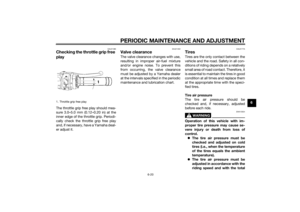 71
71 72
72 73
73 74
74 75
75 76
76 77
77 78
78 79
79 80
80 81
81 82
82 83
83 84
84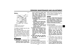 85
85 86
86 87
87 88
88 89
89 90
90 91
91 92
92 93
93 94
94 95
95 96
96 97
97 98
98 99
99 100
100 101
101 102
102 103
103 104
104 105
105 106
106 107
107 108
108 109
109 110
110 111
111
