Page 65 of 88

PERIODIC MAINTENANCE AND ADJUSTMENT
6-23
6
EAU51951
Checking the front forkThe condition and operation of the
front fork must be checked as follows
at the intervals specified in the periodic
maintenance and lubrication chart.
To check the con dition
Check the front fork for damage and
excessive oil leakage.
To check the operation 1. Place the vehicle on a level sur- face and hold it in an upright posi-
tion. WARNING! To avoi d injury,
securely support the vehicle so
there is no dan ger of it fallin g
over.
[EWA10752]
2. While applying the front brake, push down hard on the handle-
bars several times to check if the
front fork compresses and re-
bounds smoothly.
NOTICE
ECA10591
If any damag e is foun d or the front
fork does not operate smoothly,
have a Yamaha d ealer check or re-
pair it.
EAU23285
Checkin g the steerin gWorn or loose steering bearings may
cause danger. Therefore, the operation
of the steering must be checked as fol-
lows at the intervals specified in the
periodic maintenance and lubrication
chart.
1. Raise the front wheel off the ground. (See page 6-30.)
WARNING! To avoi d injury, se-
curely support the vehicle so
there is no dan ger of it fallin g
over.
[EWA10752]
2. Hold the lower ends of the front fork legs and try to move them for-
ward and backward. If any free
play can be felt, have a Yamaha
dealer check or repair the steer-
ing.
UB33E0E0.book Page 23 Monday, December 1, 2014 4:49 PM
Page 66 of 88

PERIODIC MAINTENANCE AND ADJUSTMENT
6-24
6
EAU23292
Checking the wheel b earingsThe front and rear wheel bearings must
be checked at the intervals specified in
the periodic maintenance and lubrica-
tion chart. If there is play in the wheel
hub or if the wheel does not turn
smoothly, have a Yamaha dealer
check the wheel bearings.
EAU50291
BatteryThe battery is located under the seat.
(See page 3-15.)
This model is equipped with a VRLA
(Valve Regulated Lead Acid) battery.
There is no need to check the electro-
lyte or to add distilled water. However,
the battery lead connections need to
be checked and, if necessary, tight-
ened.
WARNING
EWA10761
Electrolyte is poisonous an d
d an gerous since it contains sul-
furic aci d, which causes severe b
urns. Avoi d any contact with
skin, eyes or clothin g an d al-
ways shiel d your eyes when
workin g near b atteries. In case
of contact, ad minister the fol-
lowin g FIRST AID.
EXTERNAL: Flush with plenty of water.
INTERNAL: Drink lar ge quan-
tities of water or milk an d im-
me diately call a physician.
EYES: Flush with water for 15 minutes an d seek prompt
me dical attention.
Batteries pro duce explosive hy-
d ro gen gas. Therefore, keep
sparks, flames, ci garettes, etc.,
away from the battery an d pro-
vi de sufficient ventilation when
char gin g it in an enclose d
space.
KEEP THIS AND ALL BATTER-
IES OUT OF THE REACH OF
CHILDREN.
To char ge the battery
Have a Yamaha dealer charge the bat-
tery as soon as possible if it seems to
ha v e di s c ha r g e d. Ke e p in m in d t ha t t he
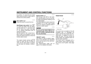
1. Positive battery lead (red)
2. Battery
3. Negative battery lead (black)
1
2
3
UB33E0E0.book Page 24 Monday, December 1, 2014 4:49 PM
Page 67 of 88

PERIODIC MAINTENANCE AND ADJUSTMENT
6-25
6
battery tends to discharge more quick-
ly if the vehicle is equipped with op-
tional electrical accessories.
NOTICE
ECA16522
To char
ge a VRLA (Valve Re gulate d
Lea d Aci d) battery, a special (con-
stant-volta ge) battery char ger is re-
quire d. Usin g a conventional b attery
char ger will damag e the battery.To store the battery
1. If the vehicle will not be used for more than one month, remove the
battery, fully charge it, and then
place it in a cool, dry place.
NOTICE: When removin g the
b attery, be sure the key is
turne d to “OFF”, then discon-
nect the neg ative lead b efore
d isconnectin g the positive lea d.
[ECA16303]
2. If the battery will be stored for
more than two months, check it at
least once a month and fully
charge it if necessary.
3. Fully charge the battery before in- stallation. NOTICE: When install-
in g the b attery, be sure the key is turne
d to “OFF”, then connect
the positive lea d before con-
nectin g the ne gative lead .
[ECA16841]
4. After installation, make sure that
the battery leads are properly con-
nected to the battery terminals.NOTICE
ECA16531
Always keep the b attery charged .
Storin g a dischar ged battery can
cause permanent b attery damag e.
EAU57711
Replacin g the fusesThe main fuse, the ABS motor fuse,
and the fuse boxes, which contain the
fuses for the individual circuits, are lo-
cated under the owner’s tool box be-
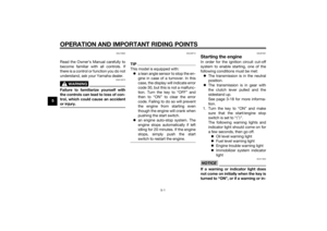
hind panel A. (See page 6-8.)1. Fuse box
2. Main fuse
3. ABS motor fuse
4. ABS motor spare fuse
3
2
4
1
UB33E0E0.book Page 25 Monday, December 1, 2014 4:49 PM
Page 68 of 88

PERIODIC MAINTENANCE AND ADJUSTMENT
6-26
6
TIPTo access the ABS motor fuse, remove
the starter relay cover by pulling it up-
ward.
If a fuse is blown, replace it as follows.1. Turn the key to “OFF” and turn off the electrical circuit in question.
2. Remove the blown fuse, and then install a new fuse of the specified
amperage. WARNING! Do not
use a fuse of a hi gher ampera ge
ratin g than recommen ded to
avoi d causin g extensive d am-
a g e to the electrical system an d
possi bly a fire.
[EWA15132]
3. Turn the key to “ON” and turn on
the electrical circuit in question to
check if the device operates.
4. If the fuse immediately blows again, have a Yamaha dealer
check the electrical system.
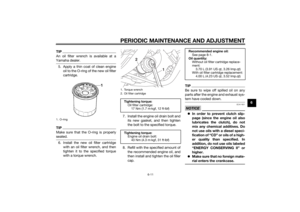
1. Ignition fuse
2. ABS control unit fuse
3. Signaling system fuse
4. Parking lighting fuse
5. Backup fuse (for clock and immobilizer sys-tem)
6. Headlight fuse
7. Spare fuse
8. Fuel injection system fuse
9. ABS solenoid fuse
2 1
4
5
6
7
789
3
1. Starter relay cover
2. ABS motor fuse
3. ABS motor spare fuse
2
1
3
Specifie d fuses:
Main fuse:
40.0 A
Headlight fuse:
20.0 A
Signaling system fuse: 7.5 A
Ignition fuse: 15.0 A
Parking lighting fuse:
15.0 A
ABS motor fuse: 30.0 A
Fuel injection system fuse: 10.0 A
ABS solenoid fuse:
15.0 A
ABS control unit fuse: 7.5 A
Backup fuse: 7.5 A
UB33E0E0.book Page 26 Monday, December 1, 2014 4:49 PM
Page 69 of 88

PERIODIC MAINTENANCE AND ADJUSTMENT
6-27
6
EAU63180
Replacing the hea dlig ht bul bThis model is equipped with a halogen
bulb headlight. If the headlight bulb
burns out, replace it as follows.NOTICE
ECA10661
Do not touch the g lass part of the
hea dlig ht bul b to keep it free from
oil, otherwise the transparency of
the glass, the luminosity of the b ulb,
an d the bul b life will be ad versely af-
fected . Thorou ghly clean off any d irt
an d fin gerprints on the head light
b ul b using a cloth moistene d with al-
cohol or thinner.1. Remove the headlight unit by re- moving the screws. 2. Disconnect the headlight coupler,
and then remove the headlight
bulb cover.
3. Unhook the headlight bulb holder, and then remove the burnt-out
bulb. 4. Place a new headlight bulb into
position, and then secure it with
the bulb holder.
5. Install the bulb cover, and then connect the coupler.
TIPWhen installing the headlight bulb cov-
er, make sure the “TOP” mark faces
upwards.
1. Do not touch the glass part of the bulb.
1. Screw
1. Headlight bulb cover
2. Headlight coupler
1
1
2
1. Headlight bulb holder
1
UB33E0E0.book Page 27 Monday, December 1, 2014 4:49 PM
Page 70 of 88
PERIODIC MAINTENANCE AND ADJUSTMENT
6-28
66. Install the headlight unit by install-
ing the screws.
7. Have a Yamaha dealer adjust the headlight beam if necessary.
EAU45226
Replacin g the auxiliary li ght
b ul b If the auxiliary light bulb burns out, re-
place it as follows.
1. Remove the headlight unit. (See page 6-27.)
2. Remove the auxiliary light bulb socket (together with the bulb) by
pulling it out.
3. Remove the burnt-out bulb by pulling it out. 4. Insert a new bulb into the socket.
5. Install the socket (together with
the bulb) by pushing it in.
6. Install the headlight unit.
1. “TOP” mark
1
1. Auxiliary light bulb socket
1
1. Auxiliary light bulb
1
UB33E0E0.book Page 28 Monday, December 1, 2014 4:49 PM
Page 71 of 88
PERIODIC MAINTENANCE AND ADJUSTMENT
6-29
6
EAU24182
Tail/brake li ghtThis model is equipped with an LED-
type tail/brake light.
If the tail/brake light does not come on,
have a Yamaha dealer check it.
EAU24215
Replacin g a turn sig nal light
b ul b1. Remove the turn signal light lens
by removing the screws.
2. Remove the burnt-out bulb by pushing it in and turning it coun-
terclockwise. 3. Insert a new bulb into the socket,
push it in, and then turn it clock-
wise until it stops.
4. Install the lens by installing the screws. NOTICE: Do not over-
ti ghten the screws, otherwise
the lens may break.
[ECA10682]
1. Screw
2. Turn signal light lens
2
1
1. Turn signal light bulb
1
UB33E0E0.book Page 29 Monday, December 1, 2014 4:49 PM
Page 72 of 88

PERIODIC MAINTENANCE AND ADJUSTMENT
6-30
6
EAU24331
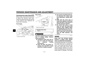
License plate lightIf the license plate light does not come
on, have a Yamaha dealer check the
electrical circuit or replace the bulb.
EAU24351
Supportin g the motorcycleSince this model is not equipped with a
centerstand, follow these precautions
when removing the front and rear
wheel or performing other mainte-
nance requiring the motorcycle to
stand upright. Check that the motorcy-
cle is in a stable and level position be-
fore starting any maintenance. A
strong wooden box can be placed un-
der the engine for added stability.
To service the front wheel
1. Stabilize the rear of the motorcy- cle by using a motorcycle stand
or, if an additional motorcycle
stand is not available, by placing a
jack under the frame in front of the
rear wheel.
2. Raise the front wheel off the ground by using a motorcycle
stand.
To service the rear wheel
Raise the rear wheel off the ground by
using a motorcycle stand or, if a motor-
cycle stand is not available, by placing a jack either under each side of the
frame in front of the rear wheel or under
each side of the swingarm.
UB33E0E0.book Page 30 Monday, December 1, 2014 4:49 PM