Page 49 of 88
PERIODIC MAINTENANCE AND ADJUSTMENT
6-7
6
Hydraulic brake service
• Regularly check and, if necessary, correct the brake fluid level.
• Every two years replace the internal components of the brake master cylinders and calipers, and change the brake fluid.
• Replace the brake hoses every four years and if cracked or damaged.
UB33E0E0.book Page 7 Monday, December 1, 2014 4:49 PM
Page 50 of 88

PERIODIC MAINTENANCE AND ADJUSTMENT
6-8
6
EAU18752
Removing an d installin g the
panelThe panel shown needs to be removed
to perform some of the maintenance
jobs described in this chapter. Refer to
this section each time the panel needs
to be removed and installed.
EAU54942
Panel A
To remove the panel1. Slide the panel lock cover open,
insert the key into the lock, and
then turn it 1/4 turn clockwise. 2. Pull the panel off as shown.
To install the panel
1. Place the panel in the original po- sition.
2. Turn the key 1/4 turn counter- clockwise, remove it, and then
slide the panel lock cover closed.
EAU19643
Checkin g the spark plu gsThe spark plugs are important engine
components, which should be
checked periodically, preferably by a
Yamaha dealer. Since heat and depos- its will cause any spark plug to slowly
erode, they should be removed and
checked in accordance with the peri-
odic maintenance and lubrication
chart. In addition, the condition of the
spark plugs can reveal the condition of
the engine.
The porcelain insulator around the
center electrode of each spark plug
should be a medium-to-light tan (the
ideal color when the vehicle is ridden
normally), and all spark plugs installed
in the engine should have the same
color. If any spark plug shows a dis-
tinctly different color, the engine could
be operating improperly. Do not at-
tempt to diagnose such problems
yourself. Instead, have a Yamaha deal-
er check the vehicle.
If a spark plug shows signs of elec-
trode erosion and excessive carbon or
other deposits, it should be replaced.
1. Panel A
1
1. Panel lock cover
2. Unlock.
1 2
UB33E0E0.book Page 8 Monday, December 1, 2014 4:49 PM
Page 51 of 88

PERIODIC MAINTENANCE AND ADJUSTMENT
6-9
6
Before installing a spark plug, the
spark plug gap should be measured
with a wire thickness gauge and, if
necessary, adjusted to specification.
Clean the surface of the spark plug
gasket and its mating surface, and
then wipe off any grime from the spark
plug threads.
TIPIf a torque wrench is not available
when installing a spark plug, a good
estimate of the correct torque is 1/4–
1/2 turn past finger tight. However, the
spark plug should be tightened to the
specified torque as soon as possible.
EAU47114
En
gine oil an d oil filter car-
tri dgeThe engine oil level should be checked
before each ride. In addition, the oil
must be changed and the oil filter car-
tridge replaced at the intervals speci-
fied in the periodic maintenance and
lubrication chart.
To check the en gine oil level
1. Place the vehicle on a level sur- face and hold it in an upright posi-
tion. A slight tilt to the side can
result in a false reading.
2. Start the engine, warm it up for several minutes, and then turn it
off.
3. Wait a few minutes until the oil set- tles.
4. Remove the engine oil filler cap, wipe the engine oil dipstick clean,
insert it back into the oil filler hole
(without screwing it in), and then
remove it again to check the oil
level.
Specifie d spark plu g:
NGK/CPR7EA-91. Spark plug gapSpark plu g g ap:
0.8–0.9 mm (0.031–0.035 in)
Ti ghtenin g torque:
Spark plug: 13 Nm (1.3 m·kgf, 9.4 ft·lbf)
UB33E0E0.book Page 9 Monday, December 1, 2014 4:49 PM
Page 52 of 88

PERIODIC MAINTENANCE AND ADJUSTMENT
6-10
6
TIPThe engine oil should be between the
minimum and maximum level marks.
5. If the engine oil is at or below theminimum level mark, add suffi-
cient oil of the recommended type
to raise it to the correct level.
6. Insert the dipstick into the oil filler hole, and then tighten the oil filler
cap.
To chan ge the en gine oil (with or
without oil filter cartri dge replace-
ment) 1. Start the engine, warm it up for several minutes, and then turn it
off.
2. Place an oil pan under the engine to collect the used oil.
3. Remove the engine oil filler cap, the engine oil drain bolt and its
gasket to drain the oil from the
crankcase.
TIPSkip steps 4–6 if the oil filter cartridge
is not being replaced.4. Remove the oil filter cartridge withan oil filter wrench.
1. Engine oil filler cap
1. Engine oil dipstick
2. Maximum level mark
3. Minimum level mark
1
1
32
1. Engine oil drain bolt
2. Gasket
1. Oil filter wrench
2. Oil filter cartridge
2
1
1
2
UB33E0E0.book Page 10 Monday, December 1, 2014 4:49 PM
Page 53 of 88

PERIODIC MAINTENANCE AND ADJUSTMENT
6-11
6
TIPAn oil filter wrench is available at a
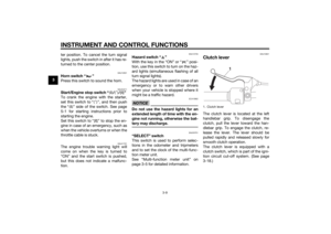
Yamaha dealer.5. Apply a thin coat of clean engine oil to the O-ring of the new oil filter
cartridge.TIPMake sure that the O-ring is properly
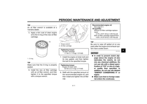
seated.6. Install the new oil filter cartridgewith an oil filter wrench, and then
tighten it to the specified torque
with a torque wrench. 7. Install the engine oil drain bolt and
its new gasket, and then tighten
the bolt to the specified torque.
8. Refill with the specified amount of the recommended engine oil, and
then install and tighten the oil filler
cap.
TIPBe sure to wipe off spilled oil on any
parts after the engine and exhaust sys-
tem have cooled down.NOTICE
ECA11621
In or der to prevent clutch slip-
pa ge (since the en gine oil also
lu bricates the clutch), do not
mix any chemical additives. Do
not use oils with a diesel speci-
fication of “CD” or oils of a hi gh-
er quality than specifie d. In
a dd ition, do not use oils la bele d
“ENERGY CONSERVING II” or
hi gher.
Make sure that no forei gn mate-
rial enters the crankcase.
1. O-ring
1. Torque wrench
2. Oil filter cartridge
Ti ghtenin g torque:
Oil filter cartridge: 17 Nm (1.7 m·kgf, 12 ft·lbf)
Ti ghtenin g torque:
Engine oil drain bolt: 43 Nm (4.3 m·kgf, 31 ft·lbf)
1
2
Recommen ded en gine oil:
See page 8-1.
Oil quantity: Without oil filter cartridge replace-
ment: 3.70 L (3.91 US qt, 3.26 Imp.qt)
With oil filter cartridge replacement:
4.00 L (4.23 US qt, 3.52 Imp.qt)
UB33E0E0.book Page 11 Monday, December 1, 2014 4:49 PM
Page 54 of 88

PERIODIC MAINTENANCE AND ADJUSTMENT
6-12
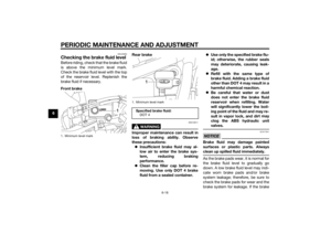
69. Start the engine, and then let it idle
for several minutes while checking
it for oil leakage. If oil is leaking,
immediately turn the engine off
and check for the cause.
TIPAfter the engine is started, the engine
oil level warning light should go off if
the oil level is sufficient.NOTICE
ECA10402
If the oil level warnin g lig ht flickers
or remains on even if the oil level is
correct, imme diately turn the en gine
off an d have a Yamaha d ealer check
the vehicle.10. Turn the engine off, wait a few minutes until the oil settles, and
then check the oil level and cor-
rect it if necessary.
EAU47081
Replacin g the air filter ele-
mentThe air filter element should be re-
placed at the intervals specified in the
periodic maintenance and lubrication
chart. Replace the air filter element
more frequently if you are riding in un-
usually wet or dusty areas.
To replace the air filter element
1. Remove the air filter case cover by removing the bolts.
2. Pull the air filter element out. 3. Insert a new air filter element into
the air filter case. NOTICE: Make
sure that the air filter element is
properly seate d in the air filter
case. The en gine shoul d never
b e operated without the air filter
element installe d, otherwise the
piston(s) an d/or cylin der(s) may
b ecome excessively worn.
[ECA10482]
4. Install the air filter case cover by
installing the bolts.
1. Bolt
2. Air filter case cover
2
1
1
1. Air filter element
1
UB33E0E0.book Page 12 Monday, December 1, 2014 4:49 PM
Page 55 of 88
 at the
inner edge of the throttle g")
PERIODIC MAINTENANCE AND ADJUSTMENT
6-13
6
EAU21385
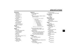
Checking the throttle grip free
playThe throttle grip free play should mea-
sure 4.0–6.0 mm (0.16–0.24 in) at the
inner edge of the throttle grip. Periodi-
cally check the throttle grip free play
and, if necessary, have a Yamaha deal-
er adjust it.
EAU21402
Valve clearanceThe valve clearance changes with use,
resulting in improper air-fuel mixture
and/or engine noise. To prevent this
from occurring, the valve clearance
must be adjusted by a Yamaha dealer
at the intervals specified in the periodic
maintenance and lubrication chart.
EAU61710
TiresTires are the only contact between the
vehicle and the road. Safety in all con-
ditions of riding depends on a relatively
small area of road contact. Therefore, it
is essential to maintain the tires in good
condition at all times and replace them
at the appropriate time with the speci-
fied tires.
Tire air pressure
The tire air pressure should be
checked and, if necessary, adjusted
before each ride.
WARNING
EWA10504
Operation of this vehicle with im-
proper tire pressure may cause se-
vere injury or d eath from loss of
control. The tire air pressure must be
checked and a djuste d on col d
tires (i.e., when the temperature
of the tires equals the am bient
temperature).
The tire air pressure must be
a d juste d in accor dance with the
ri din g spee d an d with the total
1. Throttle grip free play
1
UB33E0E0.book Page 13 Monday, December 1, 2014 4:49 PM
Page 56 of 88

PERIODIC MAINTENANCE AND ADJUSTMENT
6-14
6wei
ght of ri der, passen ger, car-
g o, an d accessories approve d
for this mo del.
WARNING
EWA10512
Never overloa d your vehicle. Opera-
tion of an overloa ded vehicle coul d
cause an acci dent.
Tire inspection
The tires must be checked before each
ride. If the center tread depth reaches
the specified limit, if the tire has a nail
or glass fragments in it, or if the side-
wall is cracked, have a Yamaha dealer
replace the tire immediately.TIPThe tire tread depth limit may differ
from country to country. Always com-
ply with the local regulations.
WARNING
EWA10472
Have a Yamaha dealer replace
excessively worn tires. Besi des
b ein g ille gal, operatin g the vehi-
cle with excessively worn tires
d ecreases rid ing sta bility an d
can lead to loss of control.
The replacement of all wheel
and b rake-relate d parts, inclu d-
in g the tires, shoul d b e left to a
Yamaha dealer, who has the
necessary professional knowl-
e dge an d experience to do so.
Ride at mo derate speed s after
chan gin g a tire since the tire
surface must first be “ broken
in” for it to develop its optimal
characteristics.Tire information
This model is equipped with tubeless
tires and tire air valves.
Tires age, even if they have not been
used or have only been used occasion-
ally. Cracking of the tread and sidewall
rubber, sometimes accompanied by
carcass deformation, is an evidence of
Tire air pressure (measure d on col d
tires): Up to 90 k g (198 l b) loa d:
Front:
225 kPa (2.25 kgf/cm², 33 psi)
Rear: 250 kPa (2.50 kgf/cm², 36 psi)
90 k g (198 l b) to maximum load :
Front: 250 kPa (2.50 kgf/cm², 36 psi)
Rear: 280 kPa (2.80 kgf/cm², 41 psi)
Maximum loa d*:
206 kg (454 lb)
* Total weight of rider, passenger, car- go and accessories
1. Tire sidewall
2. Tire tread depthMinimum tire trea d d epth (front an d
rear): 1.6 mm (0.06 in)
UB33E0E0.book Page 14 Monday, December 1, 2014 4:49 PM