2015 YAMAHA WR 250F length
[x] Cancel search: lengthPage 152 of 430
CHASSIS
4-5
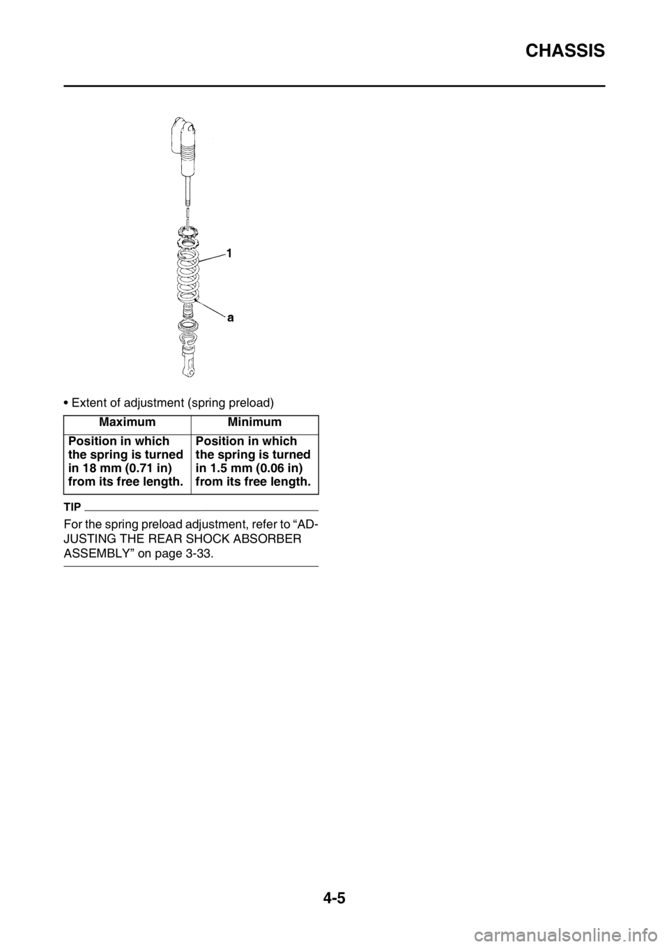
• Extent of adjustment (spring preload)
TIP
For the spring preload adjustment, refer to “AD-
JUSTING THE REAR SHOCK ABSORBER
ASSEMBLY” on page 3-33.Maximum Minimum
Position in which
the spring is turned
in 18 mm (0.71 in)
from its free length.Position in which
the spring is turned
in 1.5 mm (0.06 in)
from its free length.
Page 153 of 430

CHASSIS
4-6
EAS2GB2150SUSPENSION SETTING (FRONT FORK)
TIP
• If any of the following symptoms is experienced with the standard position as the base, make reset-
ting by reference to the adjustment procedure given in the same chart.
• Before any change, set the rear shock absorber sunken length to the standard figure 90–100 mm
(3.5–3.9 in).
SymptomSection
Check Adjust
JumpLarge
gapMedi-
um
gapSmall
gap
Stiff over entire
rangeCompression
damping forceTurn adjuster counterclock-
wise (about 2 clicks) to de-
crease damping.
Oil amount Decrease oil amount by about
5–10 cm
3 (0.2–0.3 US oz, 0.2–
0.4 Imp.oz).
Spring Replace with soft spring.
Unsmooth
movement over
entire rangeOuter tube
Inner tubeCheck for any bends, dents,
other noticeable scars, etc. If
any, replace affected parts.
Slide metal Replace with a new one for ex-
tended use.
Piston metal Replace with a new one for ex-
tended use.
Lower bracket
tightening
torqueRetighten to specified torque.
Poor initial
movementRebound
damping forceTurn adjuster counterclock-
wise (about 2 clicks) to de-
crease damping.
Oil seals Apply grease in oil seal wall.
Soft over entire
range, bottom-
ing outCompression
damping forceTurn adjuster clockwise (about
2 clicks) to increase damping.
Oil amount Increase oil amount by about
5–10 cm
3 (0.2–0.3 US oz, 0.2–
0.4 Imp.oz).
Spring Replace with stiff spring.
Stiff toward
stroke endOil amountDecrease oil amount by about
5 cm
3 (0.2 US oz, 0.2 Imp.oz).
Soft toward
stroke end, bot-
toming outOil amountIncrease oil amount by about 5
cm
3 (0.2 US oz, 0.2 Imp.oz).
Stiff initial
movementCompression
damping forceTurn adjuster counterclock-
wise (about 2 clicks) to de-
crease damping.
Page 154 of 430

CHASSIS
4-7
EAS2GB2151SUSPENSION SETTING (REAR SHOCK ABSORBER)
TIP
• If any of the following symptoms is experienced with the standard position as the base, make reset-
ting by reference to the adjustment procedure given in the same chart.
• Adjust the rebound damping in 2-click increments or decrements.
• Adjust the low compression damping in 1-click increments or decrements.
• Adjust the high compression damping in 1/6 turn increments or decrements. Low front, tend-
ing to lower
front postureCompression
damping forceTurn adjuster clockwise (about
2 clicks) to increase damping.
Rebound
damping forceTurn adjuster counterclock-
wise (about 2 clicks) to de-
crease damping.
Balance with
rear endSet sunken length for 95–100
mm (3.7–3.9 in) when one
passenger is astride seat (low-
er rear posture).
Oil amount Increase oil amount by about 5
cm
3 (0.2 US oz, 0.2 Imp.oz).
“Obtrusive”
front, tending to
upper front pos-
tureCompression
damping forceTurn adjuster counterclock-
wise (about 2 clicks) to de-
crease damping.
Balance with
rear endSet sunken length for 90–95
mm (3.5–3.7 in) when one
passenger is astride seat (up-
per rear posture).
Spring Replace with soft spring.
Oil amount Decrease oil amount by about
5–10 cm
3 (0.2–0.3 US oz, 0.2–
0.4 Imp.oz).
SymptomSection
Check Adjust
JumpLarge
gapMedi-
um
gapSmall
gap
Stiff, tending to
sinkRebound
damping forceTurn adjuster counterclock-
wise (about 2 clicks) to de-
crease damping.
Spring set
lengthSet sunken length for 90–100
mm (3.5–3.9 in) when one
passenger is astride seat.
Spongy and un-
stableRebound
damping forceTurn adjuster clockwise (about
2 clicks) to increase damping.
Low compres-
sion dampingTurn adjuster clockwise (about
1 click) to increase damping.
Spring Replace with stiff spring. SymptomSection
Check Adjust
JumpLarge
gapMedi-
um
gapSmall
gap
Page 155 of 430

CHASSIS
4-8
Heavy and
draggingRebound
damping forceTurn adjuster counterclock-
wise (about 2 clicks) to de-
crease damping.
Spring Replace with soft spring.
Poor road grip-
pingRebound
damping forceTurn adjuster counterclock-
wise (about 2 clicks) to de-
crease damping.
Low compres-
sion dampingTurn adjuster clockwise (about
1 click) to increase damping.
High compres-
sion dampingTurn adjuster clockwise (about
1/6 turn) to increase damping.
Spring set
lengthSet sunken length for 90–100
mm (3.5–3.9 in) when one
passenger is astride seat.
Spring Replace with soft spring.
Bottoming outHigh compres-
sion dampingTurn adjuster clockwise (about
1/6 turn) to increase damping.
Spring set
lengthSet sunken length for 90–100
mm (3.5–3.9 in) when one
passenger is astride seat.
Spring Replace with stiff spring.
BouncingRebound
damping forceTurn adjuster clockwise (about
2 clicks) to increase damping.
Spring Replace with soft spring.
Stiff travelHigh compres-
sion dampingTurn adjuster counterclock-
wise (about 1/6 turn) to de-
crease damping.
Spring set
lengthSet sunken length for 90–100
mm (3.5–3.9 in) when one
passenger is astride seat.
Spring Replace with soft spring. SymptomSection
Check Adjust
JumpLarge
gapMedi-
um
gapSmall
gap
Page 201 of 430
FRONT FORK
5-43
▲▲▲▲▲▲▲▲▲▲▲▲▲▲▲▲▲▲▲▲▲▲▲▲▲▲▲▲▲▲▲▲
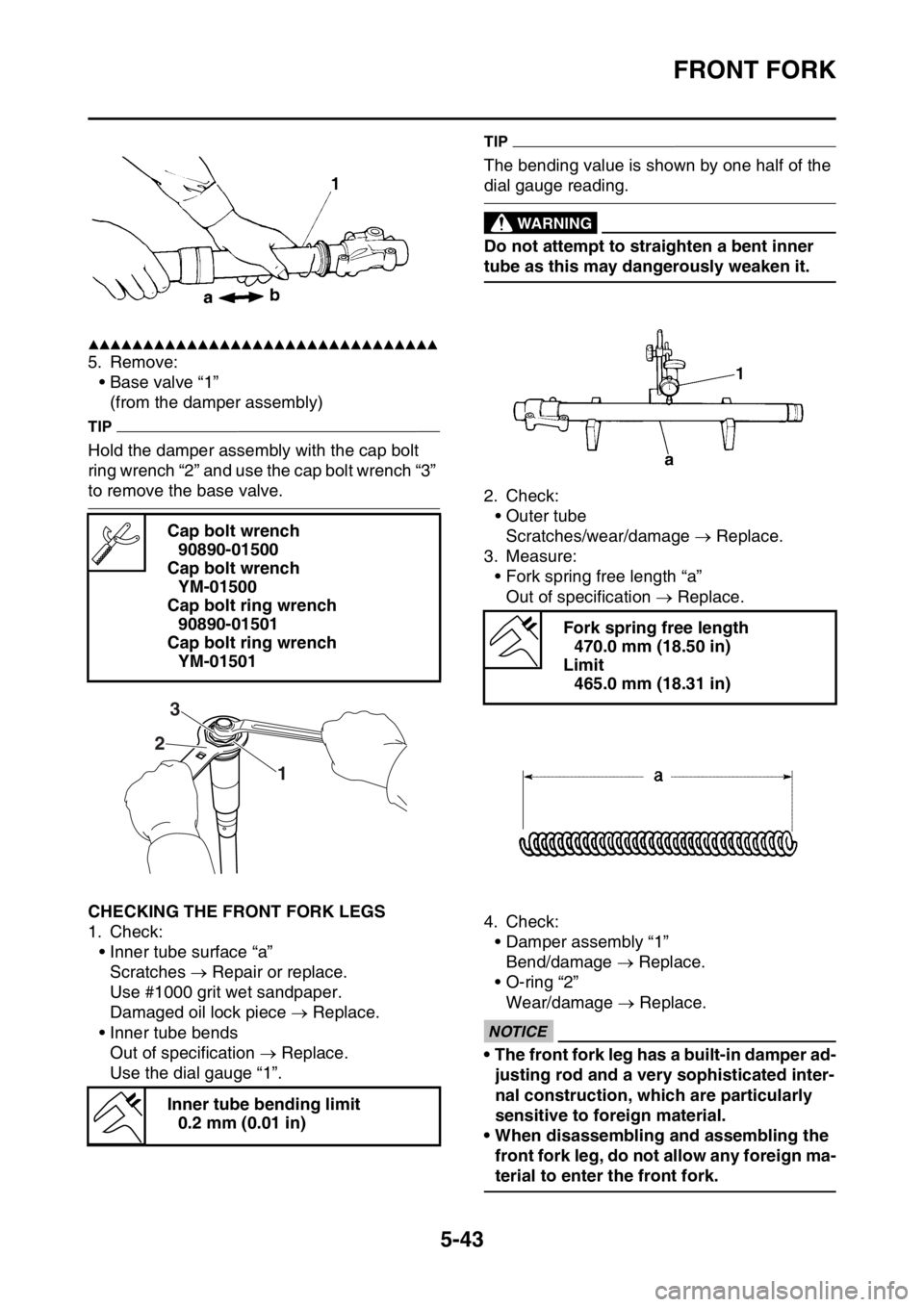
5. Remove:
• Base valve “1”
(from the damper assembly)
TIP
Hold the damper assembly with the cap bolt
ring wrench “2” and use the cap bolt wrench “3”
to remove the base valve.
EAS2GB2202CHECKING THE FRONT FORK LEGS
1. Check:
• Inner tube surface “a”
Scratches Repair or replace.
Use #1000 grit wet sandpaper.
Damaged oil lock piece Replace.
• Inner tube bends
Out of specification Replace.
Use the dial gauge “1”.
TIP
The bending value is shown by one half of the
dial gauge reading.
EWA
WARNING
Do not attempt to straighten a bent inner
tube as this may dangerously weaken it.
2. Check:
• Outer tube
Scratches/wear/damage Replace.
3. Measure:
• Fork spring free length “a”
Out of specification Replace.
4. Check:
• Damper assembly “1”
Bend/damage Replace.
• O-ring “2”
Wear/damage Replace.
ECA
NOTICE
• The front fork leg has a built-in damper ad-
justing rod and a very sophisticated inter-
nal construction, which are particularly
sensitive to foreign material.
• When disassembling and assembling the
front fork leg, do not allow any foreign ma-
terial to enter the front fork. Cap bolt wrench
90890-01500
Cap bolt wrench
YM-01500
Cap bolt ring wrench
90890-01501
Cap bolt ring wrench
YM-01501
Inner tube bending limit
0.2 mm (0.01 in)
1 23
Fork spring free length
470.0 mm (18.50 in)
Limit
465.0 mm (18.31 in)
Page 226 of 430
CHAIN DRIVE
5-68
EAS23420REMOVING THE DRIVE CHAIN
1. Stand the vehicle on a level surface.
EWA
WARNING
Securely support the vehicle so that there is
no danger of it falling over.
TIP
Place the vehicle on a suitable stand so that the
rear wheel is elevated.
2. Remove:
•Drive chain
TIP
Cut the drive chain with the drive chain cut &
rivet tool. (Use goods on the market)
EAS23441CHECKING THE DRIVE CHAIN
1. Measure:
• 15-link section of the drive chain
Out of specification Replace the drive
chain.
▼▼▼▼▼▼▼▼▼▼▼▼▼▼▼▼▼▼▼▼▼▼▼▼▼▼▼▼▼▼▼▼
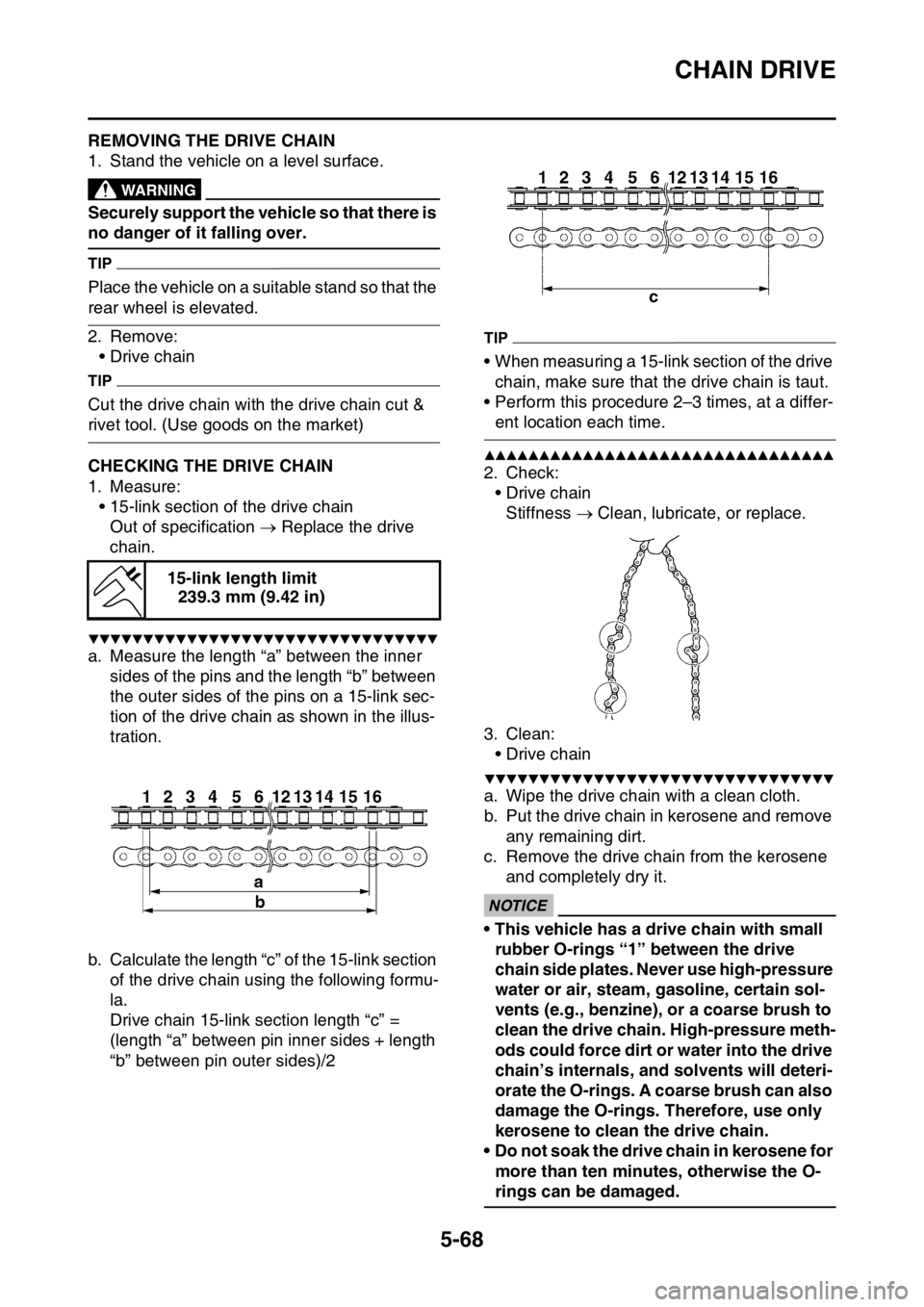
a. Measure the length “a” between the inner
sides of the pins and the length “b” between
the outer sides of the pins on a 15-link sec-
tion of the drive chain as shown in the illus-
tration.
b. Calculate the length “c” of the 15-link section
of the drive chain using the following formu-
la.
Drive chain 15-link section length “c” =
(length “a” between pin inner sides + length
“b” between pin outer sides)/2
TIP
• When measuring a 15-link section of the drive
chain, make sure that the drive chain is taut.
• Perform this procedure 2–3 times, at a differ-
ent location each time.
▲▲▲▲▲▲▲▲▲▲▲▲▲▲▲▲▲▲▲▲▲▲▲▲▲▲▲▲▲▲▲▲
2. Check:
•Drive chain
Stiffness Clean, lubricate, or replace.
3. Clean:
•Drive chain
▼▼▼▼▼▼▼▼▼▼▼▼▼▼▼▼▼▼▼▼▼▼▼▼▼▼▼▼▼▼▼▼
a. Wipe the drive chain with a clean cloth.
b. Put the drive chain in kerosene and remove
any remaining dirt.
c. Remove the drive chain from the kerosene
and completely dry it.
ECA
NOTICE
• This vehicle has a drive chain with small
rubber O-rings “1” between the drive
chain side plates. Never use high-pressure
water or air, steam, gasoline, certain sol-
vents (e.g., benzine), or a coarse brush to
clean the drive chain. High-pressure meth-
ods could force dirt or water into the drive
chain’s internals, and solvents will deteri-
orate the O-rings. A coarse brush can also
damage the O-rings. Therefore, use only
kerosene to clean the drive chain.
• Do not soak the drive chain in kerosene for
more than ten minutes, otherwise the O-
rings can be damaged. 15-link length limit
239.3 mm (9.42 in)
Page 258 of 430
VALVES AND VALVE SPRINGS
6-27
TIP
While turning the valve lapper, tap and lap the
valve seat.
e. Apply a fine lapping compound to the valve
face, and repeat the above steps.
f. After every lapping step, be sure to clean off
all of the lapping compound from the valve
face and the valve seat.
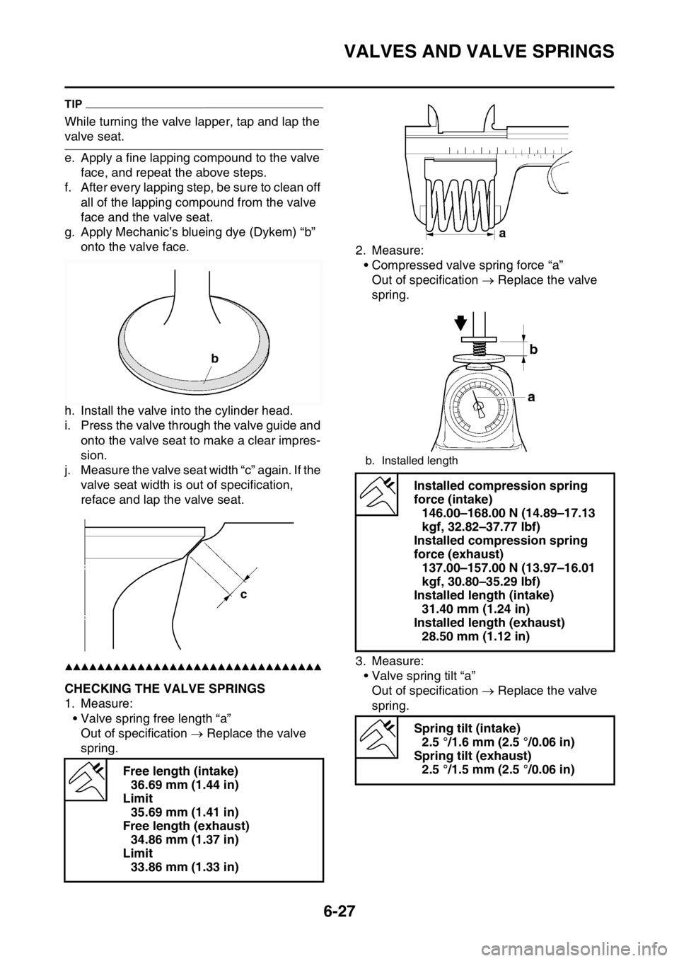
g. Apply Mechanic’s blueing dye (Dykem) “b”
onto the valve face.
h. Install the valve into the cylinder head.
i. Press the valve through the valve guide and
onto the valve seat to make a clear impres-
sion.
j. Measure the valve seat width “c” again. If the
valve seat width is out of specification,
reface and lap the valve seat.
▲▲▲▲▲▲▲▲▲▲▲▲▲▲▲▲▲▲▲▲▲▲▲▲▲▲▲▲▲▲▲▲
EAS2GB2255CHECKING THE VALVE SPRINGS
1. Measure:
• Valve spring free length “a”
Out of specification Replace the valve
spring.2. Measure:
• Compressed valve spring force “a”
Out of specification Replace the valve
spring.
3. Measure:
• Valve spring tilt “a”
Out of specification Replace the valve
spring.
Free length (intake)
36.69 mm (1.44 in)
Limit
35.69 mm (1.41 in)
Free length (exhaust)
34.86 mm (1.37 in)
Limit
33.86 mm (1.33 in)
b. Installed length
Installed compression spring
force (intake)
146.00–168.00 N (14.89–17.13
kgf, 32.82–37.77 lbf)
Installed compression spring
force (exhaust)
137.00–157.00 N (13.97–16.01
kgf, 30.80–35.29 lbf)
Installed length (intake)
31.40 mm (1.24 in)
Installed length (exhaust)
28.50 mm (1.12 in)
Spring tilt (intake)
2.5 °/1.6 mm (2.5 °/0.06 in)
Spring tilt (exhaust)
2.5 °/1.5 mm (2.5 °/0.06 in)
Page 268 of 430
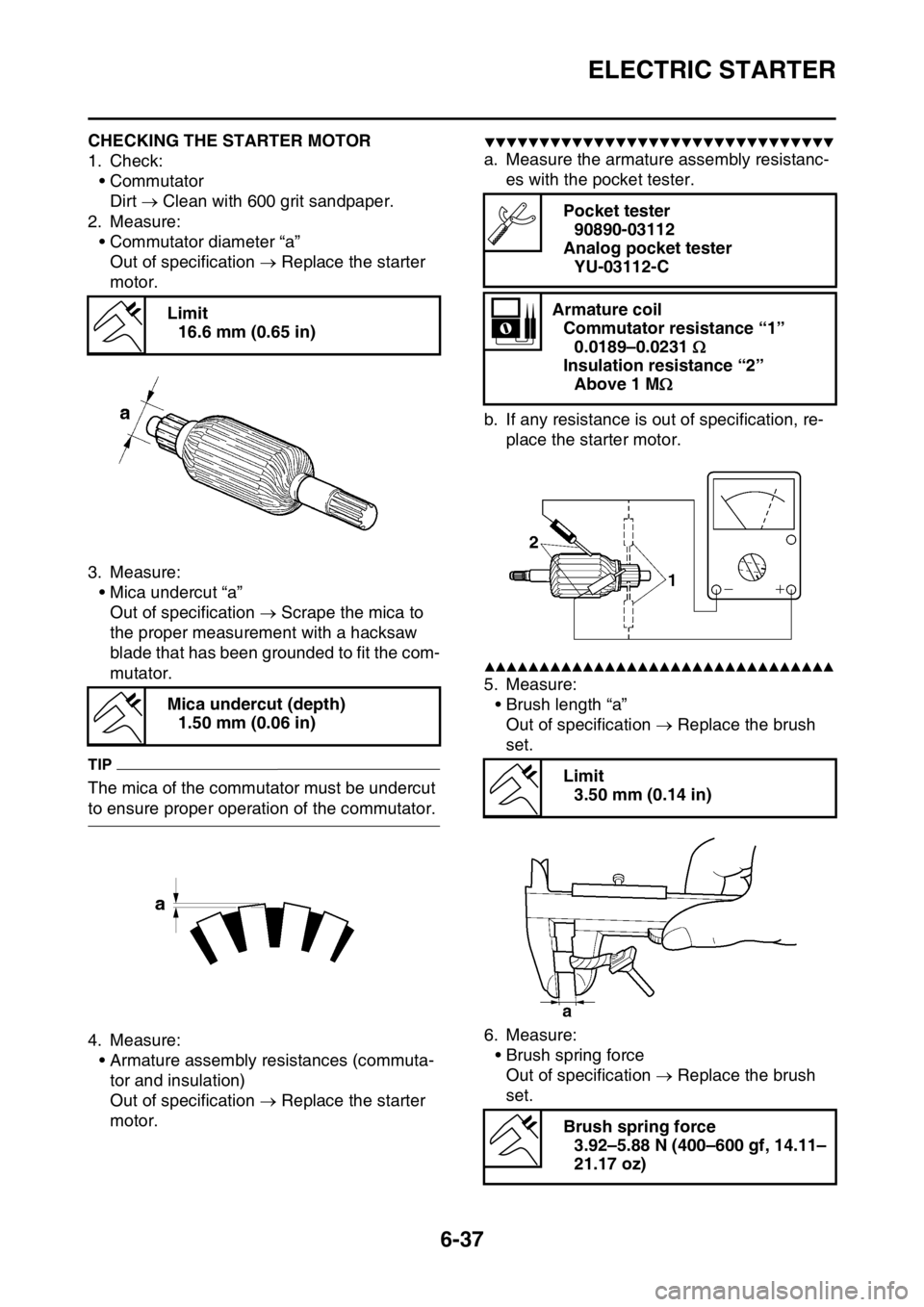
ELECTRIC STARTER
6-37
EAS2GB2265CHECKING THE STARTER MOTOR
1. Check:
•Commutator
Dirt Clean with 600 grit sandpaper.
2. Measure:
• Commutator diameter “a”
Out of specification Replace the starter
motor.
3. Measure:
• Mica undercut “a”
Out of specification Scrape the mica to
the proper measurement with a hacksaw
blade that has been grounded to fit the com-
mutator.
TIP
The mica of the commutator must be undercut
to ensure proper operation of the commutator.
4. Measure:
• Armature assembly resistances (commuta-
tor and insulation)
Out of specification Replace the starter
motor.
▼▼▼▼▼▼▼▼▼▼▼▼▼▼▼▼▼▼▼▼▼▼▼▼▼▼▼▼▼▼▼▼
a. Measure the armature assembly resistanc-
es with the pocket tester.
b. If any resistance is out of specification, re-
place the starter motor.
▲▲▲▲▲▲▲▲▲▲▲▲▲▲▲▲▲▲▲▲▲▲▲▲▲▲▲▲▲▲▲▲
5. Measure:
• Brush length “a”
Out of specification Replace the brush
set.
6. Measure:
• Brush spring force
Out of specification Replace the brush
set. Limit
16.6 mm (0.65 in)
Mica undercut (depth)
1.50 mm (0.06 in)
Pocket tester
90890-03112
Analog pocket tester
YU-03112-C
Armature coil
Commutator resistance “1”
0.0189–0.0231
Insulation resistance “2”
Above 1 M
Limit
3.50 mm (0.14 in)
Brush spring force
3.92–5.88 N (400–600 gf, 14.11–
21.17 oz)