Page 89 of 112
PERIODIC MAINTENANCE AND ADJUSTMENT
6-34
6
b
attery, be sure the key is
turne d to “OFF”, then connect
the positive lea d before con-
nectin g the ne gative lead .
[ECA16841]
8. Install the cowling.NOTICE
ECA16531
Always keep the b attery charged .
Storin g a dischar ged battery can
cause permanent battery damag e.
EAU46455
Replacin g the fusesThe main fuse and the ABS motor fuse
are located behind cowling A. (See
page 6-8.)
Fuse box 1 is located under the rider
seat. (See page 3-25.) Fuse
box 1
Fuse box 2 is located behind panel B.
(See page 6-8.)1. Main fuse
2. ABS motor fuse
3. ABS motor spare fuse
1
3
2
1. ABS solenoid fuse
2. Fuel injection system fuse
3. Spare fuse
123
U2CEE0E0.book Page 34 Wednesday, August 27, 2014 11:11 AM
Page 90 of 112

PERIODIC MAINTENANCE AND ADJUSTMENT
6-35
6Fuse
box 2
If a fuse is blown, replace it as follows. 1. Turn the key to “OFF” and turn off the electrical circuit in question.
2. Remove the blown fuse, and then install a new fuse of the specified
amperage. WARNING! Do not
use a fuse of a hi gher ampera ge
ratin g than recommen ded to avoi
d causin g extensive d am-
a g e to the electrical system an d
possi bly a fire.
[EWA15132]
3. Turn the key to “ON” and turn on
the electrical circuit in question to
check if the device operates.
4. If the fuse immediately blows again, have a Yamaha dealer
check the electrical system.
1. Ignition fuse
2. ABS control unit fuse
3. Headlight fuse
4. Backup fuse (for clock and immobilizer sys-tem)
5. Electronic throttle valve fuse
6. Radiator fan motor fuse
7. Spare fuse
8. Signaling system fuse
9. Parking lighting fuse
10.Sub radiator fan motor fuse
1 23456
7
8
10
7
9
Specifie
d fuses:
Main fuse: 50.0 A
Ignition fuse:
20.0 A
Parking lighting fuse: 7.5 A
Signaling system fuse: 7.5 A
Headlight fuse:
15.0 A
Radiator fan motor fuse: 20.0 A
Sub radiator fan motor fuse: 7.5 A
Fuel injection system fuse:
15.0 A
ABS control unit fuse: 7.5 A
ABS motor fuse: 30.0 A
ABS solenoid fuse:
15.0 A
Backup fuse: 7.5 A
Electronic throttle valve fuse: 7.5 A
U2CEE0E0.book Page 35 Wednesday, August 27, 2014 11:11 AM
Page 91 of 112

PERIODIC MAINTENANCE AND ADJUSTMENT
6-36
6
EAU46463
Replacing the hea dlig ht bul bThis model is equipped with a halogen
bulb headlight. If the headlight bulb
burns out, replace it as follows.NOTICE
ECA10651
Take care not to damag e the follow-
in g parts:
Hea dlig ht bul b
Do not touch the glass part of
the hea dlig ht bul b to keep it free
from oil, otherwise the transpar-
ency of the g lass, the luminosity
of the b ulb, an d the b ulb life will
b e ad versely affected . Thor-
ou ghly clean off any d irt and fin-
g erprints on the head light bul b
using a cloth moistene d with al-
cohol or thinner.
Hea dlig ht lens
Do not affix any type of tinted
film or stickers to the head light
lens.
Do not use a hea dlig ht bul b of a
watta ge hi gher than specified .
1. Remove the headlight unit by re-
moving the bolts.
2. Disconnect the headlight coupler, and then remove the bulb cover. 3. Unhook the headlight bulb holder,
and then remove the burnt-out
bulb.
4. Place a new headlight bulb into position, and then secure it with
the bulb holder.1. Do not touch the glass part of the bulb.
1. Bolt
1
1
1. Headlight coupler
2. Headlight bulb cover
1. Headlight bulb holder
1
2
1
U2CEE0E0.book Page 36 Wednesday, August 27, 2014 11:11 AM
Page 92 of 112
PERIODIC MAINTENANCE AND ADJUSTMENT
6-37
65. Install the headlight bulb cover,
and then connect the coupler.
6. Install the headlight unit by install- ing the bolts.
7. Have a Yamaha dealer adjust the headlight beam if necessary.
EAU46405
Replacin g the auxiliary li ght
b ul bIf the auxiliary light bulb burns out, re-
place it as follows.
1. Remove the headlight unit. (See page 6-36.)
2. Remove the auxiliary light bulb socket (together with the bulb) by
turning it counterclockwise.
3. Remove the burnt-out bulb by pulling it out of the socket. 4. Insert a new bulb into the socket.
5. Install the socket (together with
the bulb) by turning it clockwise.
6. Install the headlight unit.1. Auxiliary light bulb socket
1
1. Auxiliary light bulb
1
U2CEE0E0.book Page 37 Wednesday, August 27, 2014 11:11 AM
Page 93 of 112
PERIODIC MAINTENANCE AND ADJUSTMENT
6-38
6
EAU24182
Tail/brake li ghtThis model is equipped with an LED-
type tail/brake light.
If the tail/brake light does not come on,
have a Yamaha dealer check it.
EAU24205
Replacin g a turn sig nal light
b ul b1. Remove the turn signal light lens
by removing the screw.
2. Remove the burnt-out bulb by pushing it in and turning it coun-
terclockwise. 3. Insert a new bulb into the socket,
push it in, and then turn it clock-
wise until it stops.
4. Install the lens by installing the screw. NOTICE: Do not over-
ti ghten the screw, otherwise the
lens may break.
[ECA11192]
1. Screw
2. Turn signal light lens
1
2
1. Turn signal light bulb
1
U2CEE0E0.book Page 38 Wednesday, August 27, 2014 11:11 AM
Page 94 of 112

PERIODIC MAINTENANCE AND ADJUSTMENT
6-39
6
EAU50453
Replacing a license plate li ght
b ul b1. Remove the holding plate by re-
moving the bolts.
2. Remove the license plate light unit bolts. 3. Pull the license plate light unit out-
ward as shown to access the bulb
and its socket. 4. Remove the license plate light
bulb socket (together with the
bulb) by turning it counterclock-
wise, and then pulling it out.
5. Remove the burnt-out bulb by pulling it out.
6. Insert a new bulb into the socket.
7. Install the socket (together with the bulb) by pushing it in, and then
turning it clockwise until it stops.
8. Place the license plate light unit in the original position, and then in-
stall the bolts.
9. Install the holding plate by install- ing the bolts.1. Holding plate
2. Bolt
12
1. License plate light unit bolt
2. License plate light unit
1. License plate light bulb socket
2. License plate light unit
1
2
12
1. License plate light bulb
1
U2CEE0E0.book Page 39 Wednesday, August 27, 2014 11:11 AM
Page 95 of 112

PERIODIC MAINTENANCE AND ADJUSTMENT
6-40
6
EAU24351
Supporting the motorcycleSince this model is not equipped with a
centerstand, follow these precautions
when removing the front and rear
wheel or performing other mainte-
nance requiring the motorcycle to
stand upright. Check that the motorcy-
cle is in a stable and level position be-
fore starting any maintenance. A
strong wooden box can be placed un-
der the engine for added stability.
To service the front wheel
1. Stabilize the rear of the motorcy- cle by using a motorcycle stand
or, if an additional motorcycle
stand is not available, by placing a
jack under the frame in front of the
rear wheel.
2. Raise the front wheel off the ground by using a motorcycle
stand.
To service the rear wheel
Raise the rear wheel off the ground by
using a motorcycle stand or, if a motor-
cycle stand is not available, by placing a jack either under each side of the
frame in front of the rear wheel or under
each side of the swingarm.
EAU25872
Trou
bleshootin gAlthough Yamaha motorcycles receive
a thorough inspection before shipment
from the factory, trouble may occur
during operation. Any problem in the
fuel, compression, or ignition systems,
for example, can cause poor starting
and loss of power.
The following troubleshooting charts
represent quick and easy procedures
for checking these vital systems your-
self. However, should your motorcycle
require any repair, take it to a Yamaha
dealer, whose skilled technicians have
the necessary tools, experience, and
know-how to service the motorcycle
properly.
Use only genuine Yamaha replace-
ment parts. Imitation parts may look
like Yamaha parts, but they are often
inferior, have a shorter service life and
can lead to expensive repair bills.
WARNING
EWA15142
When checkin g the fuel system, d o
not smoke, an d make sure there are
no open flames or sparks in the ar-
ea, inclu din g pilot li ghts from water
U2CEE0E0.book Page 40 Wednesday, August 27, 2014 11:11 AM
Page 96 of 112
PERIODIC MAINTENANCE AND ADJUSTMENT
6-41
6heaters or furnaces. Gasoline or
g
asoline vapors can i gnite or ex-
plo de, causin g severe injury or prop-
erty damag e.
U2CEE0E0.book Page 41 Wednesday, August 27, 2014 11:11 AM
 1
1 2
2 3
3 4
4 5
5 6
6 7
7 8
8 9
9 10
10 11
11 12
12 13
13 14
14 15
15 16
16 17
17 18
18 19
19 20
20 21
21 22
22 23
23 24
24 25
25 26
26 27
27 28
28 29
29 30
30 31
31 32
32 33
33 34
34 35
35 36
36 37
37 38
38 39
39 40
40 41
41 42
42 43
43 44
44 45
45 46
46 47
47 48
48 49
49 50
50 51
51 52
52 53
53 54
54 55
55 56
56 57
57 58
58 59
59 60
60 61
61 62
62 63
63 64
64 65
65 66
66 67
67 68
68 69
69 70
70 71
71 72
72 73
73 74
74 75
75 76
76 77
77 78
78 79
79 80
80 81
81 82
82 83
83 84
84 85
85 86
86 87
87 88
88 89
89 90
90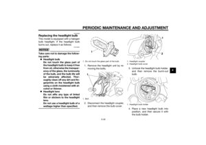 91
91 92
92 93
93 94
94 95
95 96
96 97
97 98
98 99
99 100
100 101
101 102
102 103
103 104
104 105
105 106
106 107
107 108
108 109
109 110
110 111
111![YAMAHA VMAX 2015 Owners Manual PERIODIC MAINTENANCE AND ADJUSTMENT
6-34
6
b
attery, be sure the key is
turne d to “OFF”, then connect
the positive lea d before con-
nectin g the ne gative lead .
[ECA16841]
8. Install the cow](/manual-img/51/51998/w960_51998-88.png "YAMAHA VMAX 2015 Owners Manual PERIODIC MAINTENANCE AND ADJUSTMENT
6-34
6
b
attery, be sure the key is
turne d to “OFF”, then connect
the positive lea d before con-
nectin g the ne gative lead .
[ECA16841]
8. Install the cow")


