2015 SKODA SUPERB seats
[x] Cancel search: seatsPage 111 of 276

Fig. 133
Luggage compartment cover
stowed behind the rear seats
Read and observe and on page 106 first.
If the support straps
A
» Fig. 132 are attached to the boot lid, then opening
the lid will raise the boot lid cover (hereafter referred to as cover).
If you want to carry bulky goods, the cover can be removed from the vehicle,
and may be stowed behind the rear seat backrests » Fig. 133.
Removing
›
On both sides of the boot lid unhook the straps
A
in direction of arrow
1
» Fig. 132 .
›
Hold the raised cover.
›
Press on the two sides to the underside of the cover in the region of the re-
cess
C
.
›
Take out the cover in the direction of the arrow
2
.
Fitting
›
Position the fixture
B
of the cover over the recess
C
of the side trim
» Fig. 132 .
›
Place first the front and then the rear fixture
B
.
›
Press on the two sides to the upper side of the cover in the region of the re-
cess
C
.
The fixture
B
must lock into place of the recess
C
on both sides of the lug-
gage compartment.
›
On both sides of the boot lid unhook the straps
A
.
WARNINGNo objects should be placed on the cover. This could endanger the vehicle
occupants during sudden braking or vehicle impact.CAUTION■ When closing the boot lid, jamming and damage to the cover or the side trim
panel can occur if handled incorrectly. The following guidelines must be ob-
served. ■ The fixtures B
» Fig. 132 on the cover must be engaged in the recess of
the side trim
C
.
■ The items which are transported must not exceed the height of the cover.
■ The cover must not be jammed in the surrounding seal of the luggage com-
partment lid when it is in the raised position. ■ There must be no object in the gap between the cover in the raise position
and the rear backrest.
■
Never fold the raised cover forwards to the rear seats - there is a risk of dam-
aging the cover and the boot lid.
Roll-up cover
Fig. 134
Roll-up cover: pull out / roll up / intermediate position / remove
109Transporting and practical equipment
Page 115 of 276

Usage of Cargo elements›Open the storage compartment » Fig. 138 on page 112 - .›
Remove the cargo elements in direction of arrow » Fig. 139 or » Fig. 140 -
.
›
Attach the Cargo elements with Velcro as close as possible to the rear seats
on the floor of the luggage compartment » Fig. 140 -
or attach to the fabric
side of the double-sided floor covering.
Storage compartments under the floor covering
Fig. 141
Variant 1: Lifting the floor covering / Storage compartments
Fig. 142
Variant 2: Lifting the floor covering / Storage compartments
Read and observe
and on page 106 first.
The storage compartments
B
» Fig. 141 or » Fig. 142 are located under the
floor covering of the luggage compartment in vehicles without a spare wheel.
Every storage compartment
B
is designed for storing small objects of up to 15
kg. in weight in total.
Transport of cargo - Version 1›Remove the fog floor covering in the direction of the arrow » Fig. 141.›
Fix the flooring with the loop
A
to the hook on the cargo cover or fold up in
the direction of the arrow.
›
Stow the cargo in the storage compartment.
›
Remove the flooring from the hook or fold back against the direction of the
arrow.
When transporting higher items in the trays
B
, the flooring must be flipped
forward, i.e. it must be attached to the hook of the luggage compartment cov-
er.
Transport of cargo - Version 2
›
Dividing the luggage compartment with variable loading floor » page 116.
›
Remove the fog floor covering in the direction of the arrow » Fig. 142.
›
Fix the hook
C
to the top edge of the variable loading floor.
›
Stow the cargo in the storage compartment.
›
Unhook the hook
C
and fold back the flooring opposite to the arrow.
When transporting high objects in the trays
B
the hook
C
must be hooked
onto the top edge of the variable loading floor.
CAUTION
■ The following instructions must be observed to avoid damage to the storage
compartments. ■Do not stored any sharp objects in the storage compartments.
■ Do not place any point-pressure in the storage compartment.
■ Carefully place the items in the storage compartments.■
Before closing the boot lid check that the flooring is not attached to the
hook with the loop
A
» Fig. 141 - there is a risk of damaging the hook.
■
Before closing the boot lid check that the cargo transported in the storage
compartments does not strike against the boot lid - there is a risk of damage
to the lid.
113Transporting and practical equipment
Page 118 of 276

›Fold up the variable loading floor by moving it in the direction of the arrow2.
Dividing the luggage compartment
Fig. 148
Dividing the boot with variable
loading floor
The luggage compartment can be divided with the variable loading floor in the
lower and upper position.
›
Raise the rear of the variable loading floor by the handle
A
» Fig. 148 .
›
Push the rear edge of the variable loading floor into the grooves
B
in the
direction of the arrow.
The variable loading floor is secured against movements in the grooves
B
.
Net partition
Introduction
This chapter contains information on the following subjects:
Using the net partition
116
Removing and refitting the net partition housing
117
The net partition can either be extracted from behind the rear seats or behind
the front seats.
This chapter describes the procedure for extracting and rolling up the net par-
tition behind the rear seats.
Installing and removing the net partition from behind the front seats is carried
out in a similar way as behind the rear seats. Before removing the net parti-
tion, the rear seat backrests should be folded forwards. After rolling up the net
partition in the housing, the rear seat backrests should then be folded back
» page 85 .
Using the net partitionFig. 149
Open part of the roll-up luggage compartment cover / release
lever
Fig. 150
Correctly secure net partition behind the front seats in the
pulled-out state
Removing the net partition behind the rear seats
›
Fold out part of the roll-up luggage compartment cover
A
in the direction of
the arrow » Fig. 149.
›
Pull out the net partition at the upper crossbar
C
from the housing
D
» Fig. 150.
›
Insert the transverse rod into one of the mounts
E
and push forwards.
›
Insert the transverse rod into the mount
E
on the other side of the vehicle
in the same way.
›
Make sure that the crossbar is firmly seated in the fittings
E
.
116Using the system
Page 119 of 276

›Fold back part of the roll-up luggage compartment cover A in the opposite
direction of the arrow » Fig. 149.
Using the net partition behind the rear seats›
Fold out part of the roll-up luggage compartment cover
A
in the direction of
the arrow » Fig. 149.
›
Pull the transverse rod back slightly first on one side and then on the other
and remove it from the mounts
E
» Fig. 150 .
›
Hold the crossbar
C
in such a way that the net partition can slowly roll up
into the housing
D
without being damaged.
›
Fold back part of the roll-up luggage compartment cover
A
in the opposite
direction of the arrow » Fig. 149.
CAUTION
If the net partition blocks when pulling it out of the housing, push the release
lever B in the direction of the arrow » Fig. 149.
Removing and refitting the net partition housing
Fig. 151
Removing the net partition
housing
Removing
›
Fold the rear seat backrests forward » page 85.
›
Open the rear right door » page 56.
›
Push the net partition housing
A
in the direction of the arrow
1
and re-
move it from the mounts on the right seat backrests in the direction of the
arrow
2
» Fig. 151 .
Fitting
›
Insert the recesses on the net partition housing into the mounts on the rear
seat backrests.
›
Push the net partition housing in the opposite direction of the arrow
1
» Fig. 151 as far as the stop.
›
Fold the rear seats back into their original positions » page 85.
Roof rack
Introduction
This chapter contains information on the following subjects:
fixing points for base support
118
Roof load
118WARNINGWhen transporting cargo the following the instructions must be adhered
to.■
The transported items on the roof rack must always be securely attached
– risk of accident!
■
Always secure the load with appropriate and undamaged lashing straps
or tensioning straps.
■
Distribute the load evenly over the roof rack system.
■
When transporting heavy objects or objects which take up a large area on
the roof rack system, the handling of the car may change as a result of the
displacement of the centre of gravity. The style of driving and speed must
therefore be adapted to the current circumstances.
■
Avoid abrupt and sudden driving/braking manoeuvres.
■
The permissible roof load, permissible axle loads and permissible total ve-
hicle weight must not be exceeded under any circumstances – risk of acci-
dent!
CAUTION
■ On models fitted with a sliding/tilting roof, ensure that the sliding/tilting roof
does not strike any items of luggage transported on the roof when tilting.■
Ensure that the boot lid does not hit the roof load when opened.
■
The height of the vehicle changes after mounting a roof luggage rack system
including the load that is being transported. Compare the vehicle height with
available clearances, such as underpasses and garage doors.
■
Ensure the roof aerial is not impaired by the load being transported.
Note
We recommend that you use a roof rack from ŠKODA Original Accessories.117Transporting and practical equipment
Page 176 of 276

ProActive passenger protection (following known as system) increases pas-
senger protection in the front seats in situations that could lead to vehicle im-
pact or overturning.WARNINGPlease take note of the general points relating to the use of assistance
systems » page 142, in section Introduction .
Note
The system component service life is monitored electronically. Further infor-
mation » page 35 , Safety systems .
Function
Read and observe
on page 174 first.
In critical driving situations (e.g. during emergency braking or a sudden change
in direction), the following steps can be taken separately or combined in order
to reduce the risk of serious injury.
▶ The front passenger's and driver's seatbelts, if worn, are automatically ten-
sioned closely over the body.
▶ The windows in the side doors (if open) are automatically closed up to a gap
of about 5 cm from the edge.
▶ The sliding/tilting roof is closed.
Once the critical driving situation has passed, the tension on the seatbelts will
be released again.
The system operates at two levels of protection.
The first level of protection
The system already intervenes in situations that may occur during dynamic
driving. As a result, this primarily helps to keep the driver and the passenger in
the correct seated position.
The first protection level can be deactivated in one of the following ways.
▶ The system deactivation in the Infotainment » Owner´s Manual Infotain-
ment , chapter CAR - vehicle settings .
▶ Deactivation of TCS » page 143, Braking and stabilisation systems .
▶ Selecting the driving mode
Sport
» page 171 .
Provided that the driving mode
Sport
is not selected, the system is activated
over the two levels of protection after switching the ignition off and on again.
The second level of protection
The system intervenes only if the situation is evaluated as critical, such as in
panic braking at high speeds.
This level of protection cannot be deactivated.
Vehicles with the Front Assist system
On vehicles with Front Assist the system has been expanded to include infor-
mation from the radar sensor » page 143. Using this information a system in-
tervention may also occur when there is the danger of a collision with an ob-
stacle detected in front of the vehicle.
A system intervention can only take place on the basis of the information col-
lected by the radar sensor, if the radar sensor is fully functional.
Note
If the front passenger front airbag is deactivated » page 19 the belt tensioning
function for the front passenger seat is switched off.
Lane Departure Warning (Lane Assist)
Introduction
Fig. 211
Camera viewing window for Lane
Assist
This chapter contains information on the following subjects:
Operation
175
Activation / deactivation
176
Information messages
176
The lane departure warning (following known as system) helps to keep the ve-
hicle between the boundary lines of a lane.
The system detects the boundary lines of a lane using the camera » Fig. 211.
174Driving
Page 202 of 276

CAUTION■For Alcantara ®
seat covers, do not use any solvents, floor wax, shoe cream,
stain remover, leather cleaners or similar agents.■
Avoid leaving the vehicle in bright sunlight for long periods of time in order
to stop the artificial leather, materials or Alcantara ®
from bleaching. During ex-
tended periods of standing outdoors, protect artificial leather, fabrics or Alcan-
tara ®
by covering.
■
Some clothing materials, e.g. dark denim, do not have sufficient colour fast-
ness. This can cause damage or clearly visible discolouration to seat covers,
even when used correctly. This applies particularly to light-coloured seat cov-
ers. This does not relate to a fault in the seat cover, but rather to poor colour
fastness of the clothing textiles.
Seat covers
Read and observe
and on page 198 first.
Electrically heated seats
Use a specific cleaning agent such as dry foam or similar to clean the covers.
»
.
Seats without seat heating
Thoroughly vacuum the seat covers with a vacuum cleaner before cleaning.
Clean the seat covers with a damp cloth or cleaning products specially de-
signed for this purpose.
Indented points arising on the fabrics by everyday use, can be removed by
brushing against the direction of hair with a damp brush.
Always clean all parts of the covers, so that there are no visible edges. Then
allow the seat to dry completely.
CAUTION
■ Do not clean the covers of electrically heated seats either with water or with
other liquids - there is a risk of damaging the seat heating system.■
Regularly remove dust from the seat covers using a vacuum cleaner.
■
Electrically heated seats must not be dried after cleaning by switching on the
heater.
■
Do not sit on wet seats - risk of seat deformation.
■
Always clean the seats from “seam to seam”.
Safety belts
Read and observe
and on page 198 first.
Wash dirty seat belts with mild soapy water.
Remove coarse dirt with a soft brush.
WARNING■ The seat belts must not be removed for cleaning.■Never clean the seat belts chemically as chemical cleaning products could
destroy the fabric.■
The seat belts must not be allowed to come into contact with corrosive
liquids (e.g. acids).
■
The seat belts must be fully dried before being rolled up.
200General Maintenance
Page 240 of 276

›Turn on the ignition and press the lever into position 4
» page 78 , Wind-
screen wipers and washers .
Move the windscreen wiper arms into the home position.
Replacing the rear window wiper blade
Fig. 265
Rear window wiper blade
Read and observe
on page 237 first.
Removing the wiper blade
›
Lift the wiper arm from the windscreen in the direction of
1
» Fig. 265 .
›
Tilt the wiper blade to the stop in the same direction.
›
Hold the upper part of the wiper arm and press the securing mechanism
A
in the direction of arrow
2
.
›
Remove the wiper blade in the direction of the arrow
3
.
Attaching the windscreen wiper blade
›
Push the windscreen wiper blade to the stop until it locks into place.
›
Check that the windscreen wiper blade is correctly attached.
›
Fold the wiper arm back to the windscreen.
Fuses and light bulbs
Fuses
Introduction
This chapter contains information on the following subjects:
Fuses in the dash panel – LHD
239
Fuses in the dash panel – RHD
239
Assignment of the fuses in the dash panel
240
Fuses in the engine compartment
241
Assignment of fuses in the engine compartment
241
Individual electrical circuits are protected by fuses.
Switch off the ignition and the corresponding power consuming device before
replacing a fuse.
Find out which fuse belongs to the component that is not operating
» page 240 , Assignment of the fuses in the dash panel or » page 241 , Assign-
ment of fuses in the engine compartment .
Electrically adjustable seats are protected by automatic circuit breakers, which
switch on again automatically after a few seconds after the overload has been
eliminated.
Colour coding of fuses
Fuse colourMaximum amperagelight brown5dark brown7.5red10blue15yellow/blue20white25green/pink30orange/green40red50 238Do-it-yourself
Page 242 of 276
Installing the storage compartment›Raise the storage compartment in the direction of the arrow 4.›
Overcome the resistance of the detents
A
.
›
Insert the brake control linkage in the opposite direction to arrow
2
.
›
Lock the brake control linkage in the opposite direction to arrow
1
.
›
Close the storage compartment.
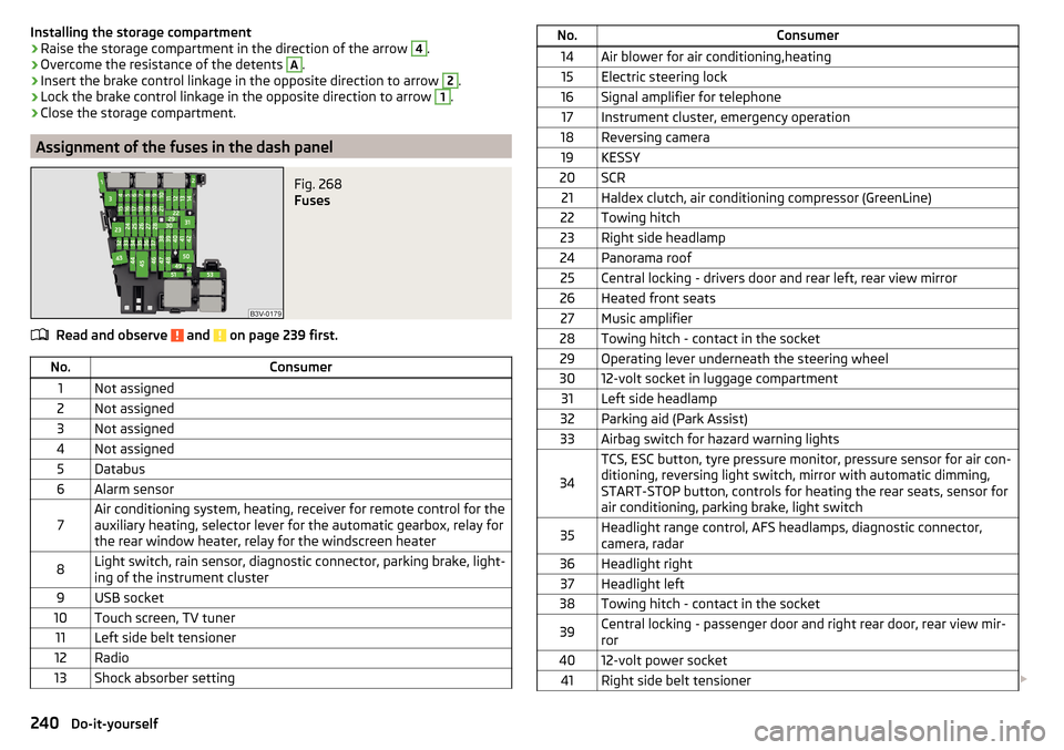
Assignment of the fuses in the dash panel
Fig. 268
Fuses
Read and observe and on page 239 first.
No.Consumer1Not assigned2Not assigned3Not assigned4Not assigned5Databus6Alarm sensor7Air conditioning system, heating, receiver for remote control for the
auxiliary heating, selector lever for the automatic gearbox, relay for
the rear window heater, relay for the windscreen heater8Light switch, rain sensor, diagnostic connector, parking brake, light-
ing of the instrument cluster9USB socket10Touch screen, TV tuner11Left side belt tensioner12Radio13Shock absorber settingNo.Consumer14Air blower for air conditioning,heating15Electric steering lock16Signal amplifier for telephone17Instrument cluster, emergency operation18Reversing camera19KESSY20SCR21Haldex clutch, air conditioning compressor (GreenLine)22Towing hitch23Right side headlamp24Panorama roof25Central locking - drivers door and rear left, rear view mirror26Heated front seats27Music amplifier28Towing hitch - contact in the socket29Operating lever underneath the steering wheel3012-volt socket in luggage compartment31Left side headlamp32Parking aid (Park Assist)33Airbag switch for hazard warning lights
34
TCS, ESC button, tyre pressure monitor, pressure sensor for air con-
ditioning, reversing light switch, mirror with automatic dimming,
START-STOP button, controls for heating the rear seats, sensor for
air conditioning, parking brake, light switch35Headlight range control, AFS headlamps, diagnostic connector,
camera, radar36Headlight right37Headlight left38Towing hitch - contact in the socket39Central locking - passenger door and right rear door, rear view mir-
ror4012-volt power socket41Right side belt tensioner 240Do-it-yourself