2015 SKODA SUPERB emergency towing
[x] Cancel search: emergency towingPage 5 of 276

Traffic jam assistant179Assistant for emergencies179
Traffic sign recognition
180
Fatigue detection
182
Tyre pressure monitoring
183
Hitch and trailer
184
Hitch
184
Trailer
185
General Maintenance
Care and maintenance
190
Service work, adjustments and technical
alterations
190
Washing vehicle
193
Cleaning vehicle exterior
194
Interior care
198
Inspecting and replenishing
201
Fuel
201
AdBlue ®
and its refilling
204
Engine compartment
206
Engine oil
209
Coolant
210
Brake fluid
212
Vehicle battery
213
Wheels
217
Tyres and wheel rims
217
Winter operation
220
Do-it-yourself
Emergency equipment and self-help
222
Emergency equipment
222
Changing a wheel
224
Puncture repair kit
228
Jump-starting
230
Towing the vehicle
231
Remote control and removable light
233Emergency unlocking/locking235Replacing windscreen wiper blades237
Fuses and light bulbs
238
Fuses
238
Bulbs
242
Technical data
Technical data
246
Basic vehicle data
246
Vehicle-specific information depending on
engine type
252
Index
3Table of Contents
Page 57 of 276

If the boot lid is closed after the vehicle has been locked and the key with
which the vehicle was locked remains in the luggage compartment, the lid will
be unlocked (partially opened). The turn signal lights flash four times as an in-
dication that the boot lid has been unlocked again. The luggage compartment
lid remains released (partially open).
The following message is shown in the instrument cluster display.Key in vehicle.KEY IN VEHICLE
CAUTION
■ Some types of gloves can affect the unlocking or locking device in the door
handle.■
After leaving the car there is no automatic locking.
Locking / unlocking the vehicle with the central locking button
Fig. 40
Central locking button
Read and observe and on page 53 first.
When the vehicle has not been locked from outside and no door is open the
button
» Fig. 40 can be used to unlock or lock the vehicle.
The locking is shown by the illuminated symbol
.
The central locking system also operates if the ignition is switched off.
The following applies after locking. ▶ Opening the doors and the boot lid from the outside is not possible.
▶ The doors can be unlocked and opened from the inside by a single pull on the
opening lever of the respective door.
WARNINGDoors locked from the inside make it difficult for rescuers to get into the
vehicle in an emergency – risk to life!
Safe securing system
Read and observe
and on page 53 first.
As soon as the vehicle is locked from the outside, the safe lock prevents open-
ing the doors from the inside.
This function is pointed out by the following message on the display of the in-
strument cluster after switching out the ignition.
Check SAFELOCK! Owner's manual!CHECK SAFELOCK
After locking the vehicle, the warning light in the driver's door flashes for
around 2 seconds in quick succession, afterwards it begins to flash evenly at
longer intervals.
Switching off
The safe lock can be switched off in one of the following ways.
▶ By locking twice within 2 seconds.
▶ By disabling the button for interior monitoring and anti-towing » page 58.
The indicator light in the driver door flashes for about 2 seconds fast, goes out and starts to flash at longer intervals after about 30 seconds.
If the vehicle is locked and the safe securing system is switched off, the door
can be opened separately from the inside by a single pull on opening lever.
The safelock switches on the next time the vehicle is locked.
WARNINGIf the car is locked and the safe securing system activated, no people must
remain in the car as it will then not be possible to either unlock a door or
open a window from the inside. The locked doors make it more difficult for
rescuers to get into the vehicle in an emergency – risk to life!55Unlocking and opening
Page 72 of 276

Fog mode
The cone of light in front of the vehicle is adjusted so that the driver is not
dazzled by the reflection of the cone of light by fog in front of the vehicle.
The mode is active at speeds of 15 – 70 km/h and if the rear fog light is switch- ed on for a period of time longer than about 10 seconds. The deactivation of
the mode is carried out a few minutes after switching off the rear fog lights.
Dynamic cornering lights
The cone of light in front of the vehicle is adjusted to the steering angle so
that the road in the curve is illuminated. This function is active at speeds
greater than 10 km.h and in all System modes.
travel mode
If the travel mode is activated, there is no automatic cone of light adaptation
in front of the vehicle.
The travel mode can be activated/deactivated in the Infotainment » Owner´s
Manual Infotainment , chapter CAR - vehicle settings .
Economy mode
When the Eco driving mode » page 171 is activated the system is in Economy
mode and there is no direction dependent light cone adaptation in front of the
vehicle.WARNINGIf there is a system malfunction the headlights are automatically lowered
to the emergency position, which prevents a possible dazzling of oncoming
traffic. This reduces the cone of light in front of the vehicle. Drive carefully
and visit a specialist garage as soon as possible.Front and rear fog lightsFig. 57
Light switch – switch on front
and rear fog lights
Read and observe on page 67 first.
Switching the fog lights on/off
›
Turn the light switch to position ,
or
» Fig. 57 .
›
Pull the light switch to position
1
, the indicator light
in the instrument
cluster lights up.
Follow the reverse order to switch off.
Switching the rear fog light on/off
›
Turn the light switch into position or
and
» Fig. 57 .
›
Pull the light switch to position
2
, the indicator light
in the instrument
cluster lights up.
Follow the reverse order to switch off.
If the vehicle is not fitted with front fog lights, the rear fog light is switched on
by pulling out the light switch to the only possible setting.
Note
While driving with an accessory connected to the trailer socket (e.g. trailer,
bike carrier) only the equipment is illuminated by the fog light. The towing de-
vice must be installed at the factory or from the ŠKODA original accessories.70Using the system
Page 225 of 276

reflective vestFig. 239
Front door: Storage compart-
ment for the reflective vest
The reflective vest can be stowed in the storage compartment
A
inside the
storage compartment of the front door » Fig. 239.
It is possible to store the reflective vests for the passengers on the rear seat in
the storage compartment in the rear doors.
Fire extinguisher
Fig. 240
Fire extinguisher
The fire extinguisher is attached by two straps in a bracket under the front
passenger's seat.
Removing/attaching
›
Loosen the two straps by pulling the buckles in the direction of the arrow
» Fig. 240 .
›
Remove the fire extinguisher.
›
Secure the fire extinguisher by placing it back into the holder and fastening
with straps.
Please read the instructions which are attached to the fire extinguisher.
Pay attention to the expiration date of the fire extinguisher. If the fire extin-
guisher is used after the expiration date, its proper function is not assured.
WARNINGThe fire extinguisher must always be secured safely so that they do not
come loose when making an emergency braking or in a vehicle collision
which could cause injuries to occupants.
Note
The fire extinguisher is part of the scope of delivery in certain countries only.
Vehicle tool kit
Fig. 241
Vehicle tool kit
The tool kit is housed in a box in the spare wheel compartment or in this stor-
age space.
Depending on the vehicle configuration, it may not contain all the compo-
nents listed in the on-board tool kit.
Screwdriver
Adapter for anti-theft wheel bolts
Towing eye
Clamps for removing the wheel trims
Jack with sign
Crank for the jack
Wheel wrench
Extraction pliers for wheel bolt caps
Breakdown kit
123456789223Emergency equipment and self-help
Page 233 of 276

Fig. 250
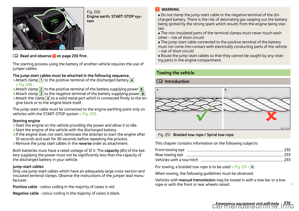
Engine earth: START-STOP sys-
tem
Read and observe on page 230 first.
The starting process using the battery of another vehicle requires the use of
jumper cables.
The jump-start cables must be attached in the following sequence.
›
Attach clamp
1
to the positive terminal of the discharged battery
A
» Fig. 249 .
›
Attach clamp
2
to the positive terminal of the battery supplying power
B
.
›
Attach clamp
3
to the negative terminal of the battery supplying power
B
.
›
Attach the clamp
4
to a solid metal part which is connected firmly to the en-
gine block or to the engine block itself.
The jump-start cable must be connected to the engine earthing point only on
vehicles with the START-STOP system » Fig. 250.
Starting engine
›
Start the engine on the vehicle providing the power and allow it to idle.
›
Start the engine of the vehicle with the discharged battery.
›
If the engine does not start, terminate the attempt to start the engine after
10 seconds and wait for 30 seconds before repeating the process.
›
Remove the jump start cables in the reverse order as attachment.
Both batteries must have a rated voltage of 12 V. The capacity (Ah) of the bat-
tery supplying the power must not be significantly less than the capacity of
the discharged battery in your vehicle.
Jump-start cables
Only use jump-start cables which have an adequately large cross-section and
insulated terminal clamps. Observe the instructions of the jumper lead manu-
facturer.
Positive cable - colour coding in the majority of cases is red.
Negative cable - colour coding in the majority of cases is black.
WARNING■
Do not clamp the jump-start cable to the negative terminal of the dis-
charged battery. There is the risk of detonating gas seeping out the battery
being ignited by the strong spark which results from the engine being star-
ted.■
The non-insulated parts of the terminal clamps must never touch each
other – risk of short circuit!
■
The jump-start cable connected to the positive terminal of the battery
must not come into contact with electrically conducting parts of the vehicle
– risk of short circuit!
■
Route the jump-start cables so that they cannot be caught by any rotat-
ing parts in the engine compartment.
Towing the vehicle
Introduction
Fig. 251
Braided tow rope / Spiral tow rope
This chapter contains information on the following subjects:
Front towing eye
232
Rear towing eye
233
Vehicles with a tow hitch
233
For towing, a braided tow rope is to be used » Fig. 251 -
.
When towing, the following guidelines must be observed.
Vehicles with manual transmission may be towed in with a tow bar or a tow
rope or with the front or rear wheels raised.
231Emergency equipment and self-help
Page 235 of 276

Removing/installing the towing eye›Manually screw the towing eye as far as it will go in the direction of the ar-
row 3
» Fig. 252 » .
For tightening purposes, we recommend, for example, using the wheel
wrench, towing eye from another vehicle or a similar object that can be pushed through the eye.
›
Unscrew the towing eye against the direction of the arrow
3
.
WARNINGThe towing eye must always be screwed in fully and firmly tightened, oth-
erwise the towing eye can tear when towing in or tow-starting.
Rear towing eye
Fig. 253
Removing the cap / fitting the towing eye
Read and observe
and on page 232 first.
Removing/installing the cap
›
Press on the fuel filler flap in the direction of the arrow
1
» Fig. 253 .
›
Remove the cap in the direction of the arrow
2
.
›
After unscrewing the towing eye, insert the cap in the area of arrow
1
.
›
Press the opposite side of the cap.
The cap must engage firmly.
Removing/installing the towing eye
›
Manually screw the towing eye as far as it will go in the direction of the ar-
row
3
» Fig. 253 » .
For tightening purposes, we recommend, for example, using the wheel
wrench, towing eye from another vehicle or a similar object that can be pushed
through the eye.›
Unscrew the towing eye against the direction of the arrow
3
.
WARNINGThe towing eye must always be screwed in fully and firmly tightened, oth-
erwise the towing eye can tear when towing in or tow-starting.
Vehicles with a tow hitch
Read and observe
and on page 232 first.
On vehicles with a factory-fitted towing device, there is no mount for the
screw-in towing eye behind and below the cap.
Use the detachable ball rod for towing » page 184, Hitch .
Towing the vehicle using the tow bar device is a viable alternative solution to
using the towing eye.
CAUTION
The ball rod and/or the vehicle can be damaged if an unsuitable tow bar is
used.
Remote control and removable light
Introduction
This chapter contains information on the following subjects:
Replacing the battery in the remote control key
234
Replace battery in KESSY key
234
Synchronising the remote control
235
replace battery in the remote control the auxiliary heating (auxiliary
heating)
235
Change batteries of the removable lamps
235
Depending on the equipment the battery can be replaced in the remote con-
trol key or KESSY key.
The key has to be synchronised if the vehicle cannot be unlocked or locked
with the key after replacing the battery » page 235.
233Emergency equipment and self-help
Page 242 of 276

Installing the storage compartment›Raise the storage compartment in the direction of the arrow 4.›
Overcome the resistance of the detents
A
.
›
Insert the brake control linkage in the opposite direction to arrow
2
.
›
Lock the brake control linkage in the opposite direction to arrow
1
.
›
Close the storage compartment.
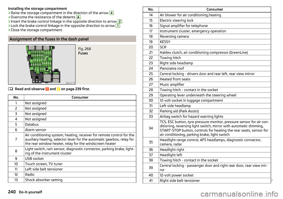
Assignment of the fuses in the dash panel
Fig. 268
Fuses
Read and observe and on page 239 first.
No.Consumer1Not assigned2Not assigned3Not assigned4Not assigned5Databus6Alarm sensor7Air conditioning system, heating, receiver for remote control for the
auxiliary heating, selector lever for the automatic gearbox, relay for
the rear window heater, relay for the windscreen heater8Light switch, rain sensor, diagnostic connector, parking brake, light-
ing of the instrument cluster9USB socket10Touch screen, TV tuner11Left side belt tensioner12Radio13Shock absorber settingNo.Consumer14Air blower for air conditioning,heating15Electric steering lock16Signal amplifier for telephone17Instrument cluster, emergency operation18Reversing camera19KESSY20SCR21Haldex clutch, air conditioning compressor (GreenLine)22Towing hitch23Right side headlamp24Panorama roof25Central locking - drivers door and rear left, rear view mirror26Heated front seats27Music amplifier28Towing hitch - contact in the socket29Operating lever underneath the steering wheel3012-volt socket in luggage compartment31Left side headlamp32Parking aid (Park Assist)33Airbag switch for hazard warning lights
34
TCS, ESC button, tyre pressure monitor, pressure sensor for air con-
ditioning, reversing light switch, mirror with automatic dimming,
START-STOP button, controls for heating the rear seats, sensor for
air conditioning, parking brake, light switch35Headlight range control, AFS headlamps, diagnostic connector,
camera, radar36Headlight right37Headlight left38Towing hitch - contact in the socket39Central locking - passenger door and right rear door, rear view mir-
ror4012-volt power socket41Right side belt tensioner 240Do-it-yourself
Page 261 of 276

Fuel supply30
Gear changes42
Service interval49
Disposal Acceptance and recycling of used vehicles
193
Distance driven31
Distance warning Warning light
40
Door Child safety lock
57
Closing56
Emergency locking236
Emergency locking the driver's door236
Opening56
Door warning41
Drive Driving through water
141
DriveGreen140
Driver Steering Recommendation (DSR)145
Driving Emissions
248
Fuel consumption248
through water141
driving data operation
43
Driving mode171
driving mode select Normal mode
172
Driving Mode Selection171
DSR145
Dynamic Light Assist72
E
ECO-TIP
49
Eco-tips49
Economical driving Tips
139
Economy mode Warning light
41
EDL145
Electrical boot lid set the top position of the lid
60
Electrical power windows Buttons in the driver's door
62
Electric boot lid Force limit
59
Manual operation59
Electric luggage compartment lid Malfunctions
61
Operating60
Electric parking brake133
Electric window lifter61, 63
Button in the passenger door63
Button in the rear doors63
Window operation malfunctions64
Electronic differential lock (EDL, XDS)145
Electronic immobilizer126
emergency replace battery in the remote control
235
Emergency Changing a wheel
224
Hazard warning light system71
Jump-starting230
Locking the door without a locking cylinder236
Locking the driver's door236
Selector lever-unlocking237
Switch off the engine by pressing a button129
Towing the using the tow hitch233
Towing the vehicle231
Tyre repair228
Unlocking the driver's door236
emergency equipment reflective vest
223
Emergency equipment Fire extinguisher
223
First aid kit222
Jack223
Vehicle tool kit223
Warning triangle222
Emissions248
Engine Information messages
38
Running-in139
Engine compartment206
Brake fluid212
Overview208
Vehicle battery213
Engine number246
engine oil specification
209
Engine oil209
Checking210
Replenishing210
Warning light38
EPC Warning light
35
ESC Operation
144
Warning light34
ESC Sport144
Exhaust emissions control system Warning light
34
F
Fastening elements
106
Fatigue detection182
Function182
Information messages182
Films195
Fire extinguisher223
First aid kit222
Floor covering Fixing
108
in the luggage compartment108
Fog lights Warning light
36
Fog Lights70
Fold in passenger's mirror80
259Index