Page 209 of 268

Tyre wear indicator and wheel replacementFig. 212
Principle sketch: Replace tire tread with wear indicators / wheels
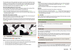
Read and observe
on page 205 first.
Wear indicators
There is a 1.6-mm-high wear indicator » Fig. 212 -
in the base of the tread of
the tyres. In some countries, different tyre wear rates may apply.
Markings on the walls of the tyres through the letters “TWI”, triangular sym- bols or other symbols identify the position of the wear indicators.
Replacing the wheels
For uniform wear on all tyres, we recommend that you replace the wheels ev-
ery 10,000 km as shown in the diagram » Fig. 212-
. You will then obtain ap-
proximately the same life for all the tyres.
After changing the wheel, the tyre pressure must be adjusted.
In vehicles with tyre pressure monitoring, save tyre pressure values
» page 165 .
WARNING■
You must have your tyres replaced with new ones at the latest when the
wear indicators have been worn down.■
Worn tyres do not provide the necessary adhesion to the road surface
particularly at high speeds on wet roads. One could experience “aquaplan- ing” (uncontrolled movements of the vehicle – “swimming” on a wet road surface).
Tyre damage
Read and observe
on page 205 first.
We recommend checking your tyres and wheel rims for damage (punctures,
cuts, splits and bulges, etc.) on a regular basis.
Remove any foreign objects in the tyre tread immediately (e.g. small stones).
Foreign bodies which have penetrated into the tyre (e.g. screws or nails)
should not be removed and seek help from a specialist garage.
WARNINGNever drive with damaged tyres – risk of accident.
CAUTION
The tyres must be protected from contact with substances such as oil, grease
and fuel, which could damage them. If the tyres come into contact with these
substances, then we recommend having them checked out in a specialist ga-
rage.
Unidirectional tyres
Read and observe
on page 205 first.
The direction of rotation of the tyres is marked by arrows on the wall of the
tyre .
The indicated direction of rotation must be adhered to in order to obtain the
best benefits from the characteristics of these tyres.
These characteristics are mainly.
▶ Increased driving stability.
▶ Reduced risk of aquaplaning.
▶ Reduced tyre noise and reduced tyre wear.
Spare wheel
Read and observe
on page 205 first.
The size of the spare wheel is identical to that of the vehicle factory installedwheels.
After changing the spare wheel, the tyre pressure must be adjusted.
207Wheels
Page 210 of 268

In vehicles with tyre pressure monitoring, save tyre pressure values
» page 165 .WARNING■
If, you get a puncture and a spare tyre has to be mounted with opposite
direction of rotation, then drive carefully. The tyre no longer retains its opti-
mal characteristics in this situation.■
If the dimensions or design of the spare wheel differ from the tyres fitted
to the vehicle (e.g. winter tyres or low-profile tyres), it must only be used
briefly in the event of a puncture and if an appropriately cautious style of
driving is adopted.
■
Never use the temporary spare wheel if it is damaged.
Spare wheel
Read and observe
on page 205 first.
A yellow warning label is always displayed on the rim of the temporary spare
wheel.
Please note the following if you intend to use the temporary spare wheel. ▶ The warning label must not be covered after installing the wheel.
▶ Be specially attentive when driving.
▶ The emergency spare is inflated to the maximum inflation pressure for the
vehicle » page 205 .
▶ The tyre inflation pressure of the spare wheel R 18 is 4.2 bar.
▶ Only use this emergency spare wheel to reach the nearest specialist garage,
as it is not intended for permanent use.
If you need to use a spare wheel, make sure to fit a standard wheel of the ap-
propriate dimensions and design as soon as possible.
In vehicles with tyre pressure monitoring, save tyre pressure values
» page 165 .
WARNING■
Never drive with more than one temporary spare wheel mounted!■Only use the temporary spare wheel when absolutely necessary.■
Avoid accelerating at full throttle, sharp braking and fast cornering.
■
The snow chains cannot be used on the temporary spare wheel.
■
If the dimensions or design of the temporary spare wheel differ from the
tyres fitted, never drive faster than 80 km/h (or 50 mph).
WARNING (Continued)■ Never use the emergency spare wheel if it is damaged.■Observe instructions on the warning sign of the emergency wheel.
Tyre label
Read and observe
on page 205 first.
Only fit radial tyres of the same type, size (rolling circumference) and the same
tread pattern on one axle on all 4 wheels.
When fitting new tyres, the tyres must be replaced axle by axle.
Explanation of tyre markings
For example, 195/65 R 15 91 T means:
195Tyre width in mm65Height/width ratio in %RCode letter for the type of tyre – Radial15Diameter of wheel in inches91Load indexTSpeed symbol
The date of manufacture is stated on the tyre wall (possibly on the inside).
For example, DOT ... 10 15... means, for example, that the tyre was manufac-
tured in the 10th week of 2015.
Load index
The load index indicates the maximum permissible load for each individual
tyre.
Load index8889909192939495Load
(In kg)560580600615630650670690
Speed symbol
The maximum speed symbol indicates the maximum permissible vehicle speed
with fitted tyres in each category.
208General Maintenance
Page 211 of 268

Speed
symbolSTUHVWYMaximum speed
(in km/h)180190200210240270300WARNING■ Never exceed the maximum permissible load bearing capacity of moun-
ted tyres.■
Never exceed the maximum permissible speed for the mounted tyres.
Winter operation
Introduction
This chapter contains information on the following subjects:
Winter tyres
209
Snow chains
209
Do not use alloy rims with bevelled or polished surfaces during the winter. The
rim surface does not have sufficient corrosion protection and could be perma-
nently damaged (e.g. through grit).
Winter tyres
The handling of your vehicle will be significantly improved when driving on
wintry roads if you fit winter tyres (labelled M+S).
To ensure the best possible handling, winter tyres must be fitted to all four
wheels. The minimum tread depth is 4 mm.
Fit the summer tyres on again in good time as they provide better handling
properties, a shorter braking distance, less tyre noise, and reduced tyre wear
on roads which are free of snow and ice as well as at temperatures above 7 °C.
Speed symbol
Winter tyres (marked with M+S and a peak/snowflake symbol
) of a lower
speed category can be used provided that the permissible maximum speed of
these tyres is not exceeded even if the possible maximum speed of the vehicle
is higher.
On vehicles with the infotainment system with key the speed limit can be
set for winter tyres » Owner´s Manual Infotainment , chapter CAR - Adjust ve-
hicle systems .
For other vehicles, there is the possibility to set the speed limit for winter tyres
at a specialist garage.
Snow chains
When driving on wintry roads, snow chains improve not only traction, but also
the braking performance.
Snow chains must only be mounted on the front wheels.
It is only permissible to fit snow chains with the following wheel/tyre combina-
tions.
Octavia
Rim sizeImpression depth DTyre size6J x 15 a)43 mm195/65 R156J x 15a)47 mm195/65 R156J x 16 b)48 mm205/55 R166J x 16b)50 mm205/55 R166J x 17b)45 mm205/50 R176J x 17 b)48 mm205/50 R17a)
Only fit snow chains with links and locks not larger than 13 mm.
b)
Only fit snow chains with links and locks not larger than 12 mm.
Octavia Scout
Rim sizeImpression depth DTyre size6J x 16 a)50 mm205/55 R166J x 17a)45 mm205/50 R176J x 16 a)48 mm205/55 R166J x 16 b)48 mm205/60 R166J x 17a)48 mm205/50 R176J x 17b)48 mm205/55 R17a)
Only fit snow chains with links and locks not larger than 12 mm.
b)
Only fit snow chains with links and locks not larger than 9 mm.
209Wheels
Page 212 of 268
Octavia RSRim sizeImpression depth DTyre size6J x 17a)45 mm205/50 R176J x 17a)48 mm205/50 R17a)
Only fit snow chains with links and locks not larger than 12 mm.
Remove the full wheel trims before fitting the snow chains » page 213.
CAUTION
The chains must be removed when driving on snow-free roads. They would
otherwise cause loss of performance and damage the tyres.210General Maintenance
Page 213 of 268

Do-it-yourself
Emergency equipment, and self-help
Emergency equipment
Introduction
This chapter contains information on the following subjects:
First aid kit and warning triangle
211
reflective vest
211
Fire extinguisher
212
Vehicle tool kit
212
First aid kit and warning triangle
Fig. 213
Placement of the first aid kit and warning triangle - version 1 /
version 2
The following information applies to the first-aid kit and warning triangle from
the ŠKODA Original Accessories.
The storage compartments may possibly be too small for a different first-aid
kit or warning triangle.
First-aid box
The first aid kit can be attached by a strap in the right-hand storage compart- ment in the luggage compartment » Fig. 213.
Warning triangle – version 1
The warning triangle can be attached to the rear wall trim panel with rubber straps » Fig. 213 -
. Natural gas vehicles have the warning triangle located
under the floor mat in the luggage compartment.
Warning triangle – version 2
The warning triangle can be secured with straps in the right storage compart-
ment in the luggage compartment » Fig. 213 -
.
Pay attention to the expiration date of the first-aid kit.WARNINGThe first-aid kit and warning triangle must always be secured safely so that
they do not come loose when making an emergency braking or in a vehicle
collision which could cause injuries to occupants.
Note
We recommend using a first-aid box from ŠKODA Original Accessories available
from a ŠKODA Partner.
reflective vest
Fig. 214
Storage compartment for the re-
flective vest
The reflective vest can be stored in brackets under the front seats » Fig. 214.
211Emergency equipment, and self-help
Page 214 of 268

Fire extinguisherFig. 215
Fire extinguisher
The fire extinguisher is attached by two straps in a holder underneath the driv-
er's seat.
Removing/attaching
›
Loosen the two straps by pulling the buckles in the direction of the arrow
» Fig. 215 .
›
Remove the fire extinguisher.
›
To fit in place, insert the fire extinguisher back into the bracket and secure
with straps.
Please read the instructions which are attached to the fire extinguisher.
Pay attention to the expiration date of the fire extinguisher. If the fire extin- guisher is used after the expiration date, its proper function is not assured.
WARNINGThe fire extinguisher must always be secured safely so that they do not
come loose when making an emergency braking or in a vehicle collision
which could cause injuries to occupants.
Note
The fire extinguisher is part of the scope of delivery in certain countries only.Vehicle tool kitFig. 216
Vehicle tool kit
The tool kit is housed in a box in the spare or emergency wheel compartment
or in this storage space.
Depending on the equipment variant, the vehicle tool kit may not contain all
of the following components.
Screwdriver
Key for removing and installing the tail light
Adapter for anti-theft wheel bolts
Towing eye
Clamps for removing the wheel trims
Jack with sign
Crank for the jack
Wheel wrench
Extraction pliers for wheel bolt caps
Breakdown kit
WARNINGThe factory-supplied lifting jack is only intended for your model of vehicle.
Under no circumstances attempt to lift heavier vehicles or other loads. 12345678910212Do-it-yourself
Page 215 of 268

CAUTION■Screw the jack back into the starting position before storing in the box with
the vehicle tool kit.■
Ensure that the vehicle tool kit is safely secured in the luggage compart-
ment.
■
Ensure that the box is always secured with the strap.
Note
The declaration of conformity is included with the jack or the log folder.
Changing a wheel
Introduction
This chapter contains information on the following subjects:
Preparation
213
Removing/stowing the wheel
213
Full wheel trim
213
Wheel bolts
214
Anti-theft wheel bolts
214
Loosening/tightening wheel bolts
215
Raising the vehicle
215
Remove the wheel / fix
216
Follow-up tasks
216
For your own safety and the safety of your passengers, the following instruc-
tions must be observed before carrying out a wheel change on the road.
Switch on the hazard warning light.
Place the warning triangle at the prescribed distance.
Park the vehicle as far away as possible from flowing traffic.
Choose a location with a flat, solid surface.
Have all the occupants get out. The passengers should not stand on the
road (instead they should remain behind a crash barrier, for instance) while
the wheel is being changed.
Preparation
Before changing the wheel, the following work must be carried out.
›
Switch off the engine.
› For vehicles with
manual transmission select 1st gear.›On vehicles with automatic transmission , place the selector lever in the P
position.›
The parking brake switch.
›
Uncouple any trailers.
Removing/stowing the wheel
Fig. 217
Take out the wheel
The wheel is located in a well under the floor covering in the boot and is fixed
in place with special bolt
B
» Fig. 217 .
Take out the wheel
›
Open the boot lid.
›
Raise the floor covering in the boot » page 103.
›
Loosen the retaining belt and take out the box with the tool kit.
›
Remove locking
A
in the direction of arrow
1
» Fig. 217 .
›
Unscrew nut
B
in the direction of arrow
2
.
›
Remove the wheel.
Store wheel away
›
Place the wheel into the wheel well with the wheel rim pointing downward.
›
Pull the fixing band through the opposite holes in the wheel rim.
›
Screw in nut
B
in the opposite direction to arrow
2
» Fig. 217 .
›
Insert locking
A
in the opposite direction to which arrow
1
is pointing.
›
Replace the box with the tool kit into the emergency or spare wheel and se-
cure it with the tape.
›
Fold back the floor covering in the boot » page 107.
›
Shut the boot lid.
Full wheel trim
Before removing the wheel bolts, remove the full wheel trim.
213Emergency equipment, and self-help
Page 216 of 268

Extracting›Hook the clamp found in the vehicle tool kit » page 212 into the reinforced
edge of the wheel trim.›
Push the wheel wrench through the clamp, support on the tyre and pull off
the wheel trim.
Installing
›
Press the wheel trim onto the wheel rim at the designated valve opening.
›
Then press the trim into the wheel rim until its entire circumference locks
correctly in place.
Notes on wheel trims supplied at the factory or from ŠKODAOriginal Accesso-
ries. ▶ When using an anti-theft wheel bolt, make sure that this has been fitted ac-
cording to the position marked on the back of the wheel cover position.
▶ On the back of the wheel cover, the position for the anti-theft wheel bolt is
marked by means of a symbol. If the wheel cover is set outside the position
marked for the anti-theft wheel bolt, there is a risk of damaging the wheel
cover.
If wheel trims are fitted, an adequate flow of air must be assured in order to
cool the brake system.
CAUTION
Use the pressure of your hand only, do not strike the full wheel trim. The cover
could be damaged.
Note
We recommend that you use hub caps from ŠKODA Original Accessories.
Wheel bolts
Fig. 218
Remove the cap
Before removing the wheel bolts, remove the caps.
Extracting›Push the extraction pliers » page 212 sufficiently far onto the cap until the
inner catches of the pliers are positioned at the collar of the cap.›
Remove the cap in the direction of the arrow » Fig. 218.
Fitting
›
Push the cap onto the wheel bolt up to the stop.
Anti-theft wheel bolts
Fig. 219
Principle sketch: Anti-theft
wheel bolt with adapter
The anti-theft wheel bolts protect the wheels from theft. These can only be
loosened or tightened with the use of adapter
B
» Fig. 219 .
›
Remove the full wheel trim or the caps of the wheel bolts.
›
Insert adapter
B
» Fig. 219 with the toothed side all the way into the inner
teeth in the head of the anti-theft wheel bolts
A
.
›
Push the wheel wrench onto the adapter
B
up to the stop.
›
Loosen or tighten the wheel bolt » page 215.
›
Remove the adapter.
›
Replace the wheel trim and the caps.
The adapter for the anti-theft wheel bolts must always be kept in the vehicle
in preparation for a possible wheel change. The adapter is stowed in the tool
kit.
With wheel trims supplied at the factory or from ŠKODA Original Accessories,
the position of the anti-theft wheel bolt is marked on the back of the wheel
trim.
When using an anti-theft wheel bolt, make sure that this has been fitted ac-
cording to the position marked on the back of the wheel cover position.
214Do-it-yourself