Page 207 of 270

5.7
TYRE INFLATION KIT (4/5)
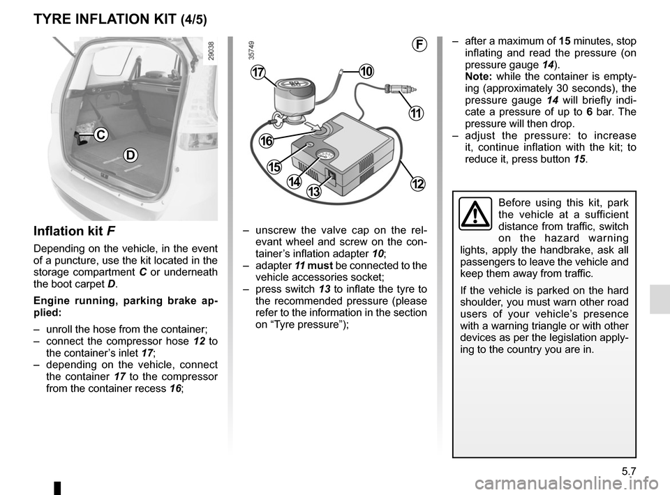
Inflation kit F
Depending on the vehicle, in the event
of a puncture, use the kit located in the
storage compartment C or underneath
the boot carpet D.
Engine running, parking brake ap-
plied:
– unroll the hose from the container;
– connect the compressor hose 12 to
the container’s inlet 17;
– depending on the vehicle, connect the container 17 to the compressor
from the container recess 16; – unscrew the valve cap on the rel-
evant wheel and screw on the con-
tainer’s inflation adapter 10;
– adapter 11 must be connected to the
vehicle accessories socket;
– press switch 13 to inflate the tyre to
the recommended pressure (please
refer to the information in the section
on “Tyre pressure”);
C
D
1314
1017
11
12
16
15
F
Before using this kit, park
the vehicle at a sufficient
distance from traffic, switch
on the hazard warning
lights, apply the handbrake, ask all
passengers to leave the vehicle and
keep them away from traffic.
If the vehicle is parked on the hard
shoulder, you must warn other road
users of your vehicle’s presence
with a warning triangle or with other
devices as per the legislation apply-
ing to the country you are in.
– after a maximum of 15 minutes, stop inflating and read the pressure (on
pressure gauge 14).
Note: while the container is empty-
ing (approximately 30 seconds), the
pressure gauge 14 will briefly indi-
cate a pressure of up to 6 bar. The
pressure will then drop.
– adjust the pressure: to increase it, continue inflation with the kit; to
reduce it, press button 15.
Page 210 of 270
5.10
TOOLS (2/2)/WHEEL TRIM
12
A
BC
D
Wheel trim
Remove it using the hubcap tool 4 by
connecting the hook in the recess pro-
vided next to the valve 12 (to attach the
metal clip).
To refit the wheel trim, align it with
valve 12. Push the retaining hooks in
fully, starting with side A near the valve,
followed by B and C, finishing at D op-
posite the valve.
Note: if you are using anti-theft bolts,
please refer to the information on
“Changing a wheel”.
5-seater version
Lift the boot carpet 10, and secure it
with the hook.
The tools are found in the support 11.
7-seater version
The tools are in the compartment 9 of
the boot: lift the third row rear right-
hand seat, pull the tab 8, then take out
the bag containing the tools.
To put it back, fold the jack fully, then
store and replace the tool bag in its
housing. Check that the assembly is
correctly positioned (to avoid noise).
9
8
10
11
Page 233 of 270

5.33
TOWING: breakdown (2/2)
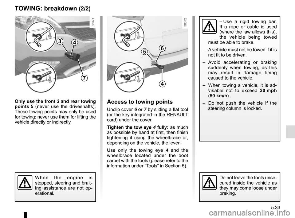
Only use the front 3 and rear towing
points 5 (never use the driveshafts).
These towing points may only be used
for towing: never use them for lifting the
vehicle directly or indirectly.Access to towing points
Unclip cover 6 or 7 by sliding a flat tool
(or the key integrated in the RENAULT
card) under the cover.
Tighten the tow eye 4 fully: as much
as possible by hand at first, then finish
tightening it using the wheelbrace or,
depending on the vehicle, the lever.
Use only the towing eye 4 and the
wheelbrace located under the boot
carpet with the tools (please refer to the
information under “Tools” in Section 5).
When the engine is
stopped, steering and brak-
ing assistance are not op-
erational.Do not leave the tools unse-
cured inside the vehicle as
they may come loose under
braking.
– Use a rigid towing bar.
If a rope or cable is used
(where the law allows this),
the vehicle being towed
must be able to brake.
– A vehicle must not be towed if it is not fit to be driven.
– Avoid accelerating or braking suddenly when towing, as this
may result in damage being
caused to the vehicle.
– When towing a vehicle, it is ad- visable not to exceed 30 mph
(50 km/h).
– Do not push the vehicle if the steering column is locked.
3
7
4
56
4