Page 125 of 425
UNDERSTANDING YOUR INSTRUMENT PANEL
CONTENTS
�INSTRUMENT PANEL FEATURES ..........126
� INSTRUMENT CLUSTER .................127
� INSTRUMENT CLUSTER DESCRIPTIONS .....128
� ELECTRONIC VEHICLE INFORMATION CENTER
(EVIC) ...............................141
▫ Electronic Vehicle Information Center (EVIC)
Setup Menu ........................ .143
▫ Change Engine Oil Indicator System ........145
▫ Trip Computer .......................146
▫ Trip Button ..........................146 ▫
Trip Functions .......................147
▫ Values Displayed ..................... .147
▫ Personal Settings
(Customer-Programmable Features) ........148
� Uconnect® RH3 ........................149
▫ Introduction ........................ .149
▫ Recommendations .....................150
▫ Identification Number ..................151
▫ Security Code ........................151
▫ General ............................ .1524
Page 126 of 425

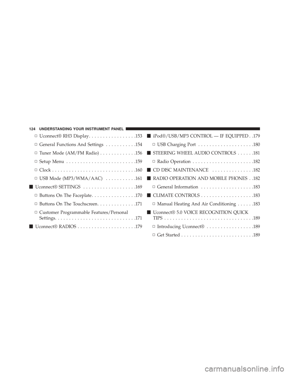
▫Uconnect® RH3 Display .................153
▫ General Functions And Settings ...........154
▫ Tuner Mode (AM/FM Radio) .............156
▫ Setup Menu ........................ .159
▫ Clock ............................. .160
▫ USB Mode (MP3/WMA/AAC) ...........161
� Uconnect® SETTINGS ...................169
▫ Buttons On The Faceplate ................170
▫ Buttons On The Touchscreen ..............171
▫ Customer Programmable Features/Personal
Settings ............................ .171
� Uconnect® RADIOS .....................179 �
iPod®/USB/MP3 CONTROL — IF EQUIPPED . .179
▫ USB Charging Port ....................180
� STEERING WHEEL AUDIO CONTROLS ......181
▫ Radio Operation ..................... .182
� CD DISC MAINTENANCE ...............182
� RADIO OPERATION AND MOBILE PHONES . .182
▫ General Information ...................183
� CLIMATE CONTROLS ...................183
▫ Manual Heating And Air Conditioning ......183
� Uconnect® 5.0 VOICE RECOGNITION QUICK
TIPS ............................... .189
▫ Introducing Uconnect® .................189
▫ Get Started ..........................189
124 UNDERSTANDING YOUR INSTRUMENT PANEL
Page 131 of 425

6. Park/Headlight ON Indicator — If EquippedThis indicator will illuminate when the park
lights or headlights are turned on.
7. Odometer/Trip Odometer/Electronic Vehicle Informa-
tion Center (EVIC) Display Area
This display indicates the total distance the vehicle has
been driven.
U.S. Federal regulations require that upon transfer of
vehicle ownership, the seller certify to the purchaser the
correct mileage that the vehicle has been driven. If your
odometer needs to be repaired or serviced, the repair
technician should leave the odometer reading the same
as it was before the repair or service. If s/he cannot do so,
then the odometer must be set at zero, and a sticker must
be placed in the door jamb stating what the mileage was
before the repair or service. It is a good idea for you to
make a record of the odometer reading before the repair/ service, so that you can be sure that it is properly reset, or
that the door jamb sticker is accurate if the odometer
must be reset at zero.
Shift Lever Status (PRND)
The shift lever status “P,R,N,D,1,2,3,4,5,6” are displayed
indicating the shift lever position. Telltales “1,2,3,4,5,6”
indicate the manual mode has been engaged and the gear
selected is displayed. Refer to “Six-Speed Automatic
Transmission” in “Starting And Operating” for further
information on ERS.
8. External Light Failure Indicator — If Equipped
The External Light Failure Indicator will come
on when a failure to one of the following lights
is detected:
• Direction Indicators
• Backup Lights
• Parking Lights
4
UNDERSTANDING YOUR INSTRUMENT PANEL 129
Page 143 of 425
ELECTRONIC VEHICLE INFORMATION CENTER
(EVIC)
The Electronic Vehicle Information Center (EVIC) fea-
tures a driver-interactive display that is located in the
instrument cluster.This system allows the driver to select a variety of useful
information by pushing the switches mounted on the
instrument panel. The EVIC Menu items consists of the
following:
•
Speed Beep
• Trip B Data
• Set Time
• Set Date
• Autoclose
• Units
• Language
• Buzzer Volume
• Seat Belt Buzzer (*)
• (*) just available after SBR disable made by CHR
Service
Electronic Vehicle Information Center (EVIC) Display
4
UNDERSTANDING YOUR INSTRUMENT PANEL 141
Page 144 of 425
•Service (Diesel Only)
• DRL - Daytime Running Light (if equipped)
• Exit Menu
The system allows the driver to select information by
pushing the following buttons mounted on the instru-
ment panel to the left of the steering column:
•MODE Button
Push and HOLD the MODE button for a time longer than
1 second to access/select the information screens or
submenu screens of a main menu item. Push and hold the
MODE button for two seconds to reset displayed/
selected features that can be reset.
EVIC Control Buttons
142 UNDERSTANDING YOUR INSTRUMENT PANEL
Page 146 of 425

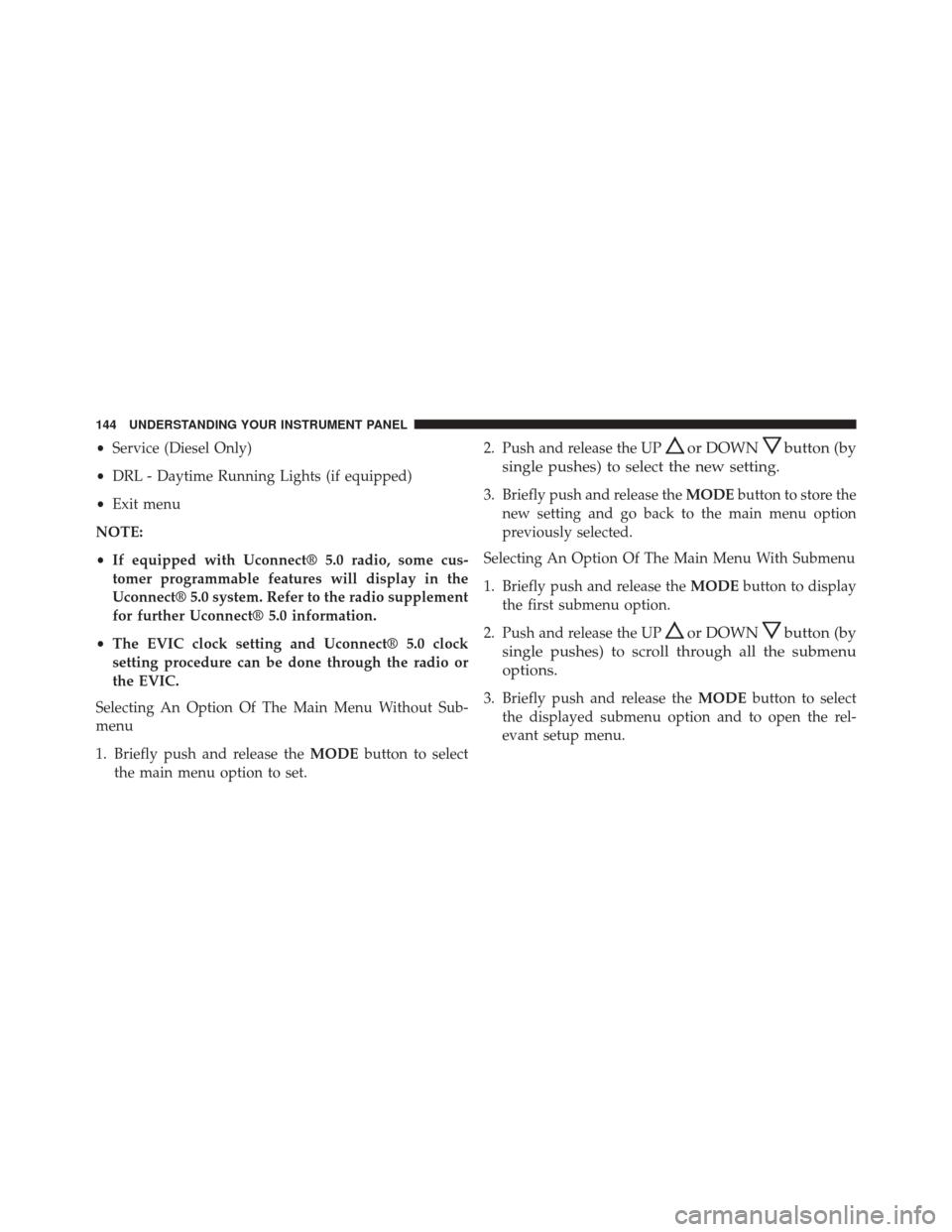
•Service (Diesel Only)
• DRL - Daytime Running Lights (if equipped)
• Exit menu
NOTE:
• If equipped with Uconnect® 5.0 radio, some cus-
tomer programmable features will display in the
Uconnect® 5.0 system. Refer to the radio supplement
for further Uconnect® 5.0 information.
• The EVIC clock setting and Uconnect® 5.0 clock
setting procedure can be done through the radio or
the EVIC.
Selecting An Option Of The Main Menu Without Sub-
menu
1. Briefly push and release the MODEbutton to select
the main menu option to set. 2. Push and release the UPor DOWNbutton (by
single pushes) to select the new setting.
3. Briefly push and release the MODEbutton to store the
new setting and go back to the main menu option
previously selected.
Selecting An Option Of The Main Menu With Submenu
1. Briefly push and release the MODEbutton to display
the first submenu option.
2. Push and release the UP
or DOWNbutton (by
single pushes) to scroll through all the submenu
options.
3. Briefly push and release the MODEbutton to select
the displayed submenu option and to open the rel-
evant setup menu.
144 UNDERSTANDING YOUR INSTRUMENT PANEL
Page 147 of 425

4. Push and release the UPor DOWNbutton (by
single pushes) to select the new setting for this
submenu option.
5. Briefly push and release the MODEbutton to store the
new setting and go back to the previously selected
submenu option.
6. Push and release and hold the MODEbutton to return
to the main menu (short hold) or the main screen
(longer hold).
Change Engine Oil Indicator System
Change Engine Oil
Your vehicle is equipped with an engine oil change
indicator system. The “Change Engine Oil” message will
display in the EVIC display. The engine oil change
indicator system is duty cycle based, which means the
engine oil change interval may fluctuate, dependent
upon your personal driving style. Unless reset, this message will continue to display each
time you turn the ignition switch to the ON/RUN
position. To turn off the message temporarily, push and
release the
MODEbutton. To reset the oil change indi-
cator system (after performing the scheduled mainte-
nance), refer to the following procedure.
1. Turn the ignition switch to the ON position (do not start the engine).
2. Fully push the accelerator pedal slowly, three times, within 10 seconds.
3. Turn the ignition switch to the OFF/LOCK position.
NOTE: If the indicator message illuminates when you
start the vehicle, the oil change indicator system did not
reset. If necessary, repeat this procedure.
4
UNDERSTANDING YOUR INSTRUMENT PANEL 145
Page 148 of 425

Trip Computer
The Trip Computer is located in the instrument cluster. It
features a driver-interactive display (displays informa-
tion such as trip information, range, fuel consumption,
average speed, and travel time).
Trip Button
TheTRIP button, located on the right steering column
stalk, can be used to display and to reset the previously
described values.
• A short button push displays the different values.
• A long button push resets the system and then starts a
new trip.
New Trip
To reset:
•Push and hold the TRIPbutton to reset the system
manually. •
When the “Trip distance” reaches 9999.9 miles or
kilometers or when the “Travel time” reaches 999.59
(999 hours and 59 minutes), the system is reset auto-
matically.
• Disconnecting/Reconnecting the battery resets the
system.
NOTE: If the reset operation occurs in the presence of
the screens concerning Trip A or Trip B, only the infor-
mation associated with Trip A or Trip B functions will be
reset.
Start Of Trip Procedure
With the ignition on, push and hold the TRIPbutton for
over one second to reset.
Exit Trip
To exit the Trip function, wait until all the values have
been displayed or hold the MENUbutton for longer than
one second.
146 UNDERSTANDING YOUR INSTRUMENT PANEL