Page 129 of 348
main menu item. Push and hold the SET/BACK arrow
button to return to the main menu from an info screen or
sub-menu item.
Electronic Vehicle Information Center (EVIC)
Setup Menu
The menu comprises a series of functions arranged in a
cycle. Push the UP
and DOWNbuttons to access
the different options and settings (setup).
The setup menu can be activated by pushing theSET/
BACKbutton. Single push on the UP
or DOWN
buttons will scroll through the setup menu op-
tions. The menu includes the following functions:
•Menu
•Speed Buzzer
•Trip B/Data
•Set Time•Set Date
•Autoclose
•Units
•Language
•Buzzer Volume
•Service
•Daylights (D.R.L.) – If Equipped
•Exit Menu
Selecting An Option Of The Main Menu Without
Submenu
1. Briefly push theSET/BACKbutton to select the main
menu option to set.
2. Push the UP
or DOWNbutton (by a single
push) to select the new setting.
4
UNDERSTANDING YOUR INSTRUMENT PANEL 127
Page 137 of 348
To adjust the volume proceed as follows:
1. Briefly push theSET/BACKbutton. The previously
set volume “level” will flash on the display.
2. Push and release the UP
or DOWNbutton for
setting.
3. Briefly push theSET/BACKbutton to go back to the
menu screen, or push and hold theSET/BACKbutton
(approximately one second) to go back to the main
screen without storing the settings.
Service (Scheduled Servicing) — If Equipped
With this function it is possible to view information on
mileage intervals for servicing.To obtain this information, proceed as follows:
Push theSET/BACKbutton briefly. The display shows
the service interval in miles (mi) or kilometers (km)
according to the previous setting (see the�Unit Of
Measurement�paragraph).
Briefly push theSET/BACKbutton to go back to the
menu screen or hold the button down to go back to the
standard screen.
4
UNDERSTANDING YOUR INSTRUMENT PANEL 135
Page 138 of 348

NOTE:The “Scheduled Servicing Plan” includes car
maintenance at fixed intervals, refer to the�Maintenance�
chapter. This message is displayed automatically along
with the
warning light when the key is turned to
MAR-ON - 1242 miles (2,000 km) before these dead-
lines and reappears every 124 miles (200 km). Below
124 miles (200 km) servicing indications are more
frequent. The indication will appear in miles or kilo-
meters according to the�Unit Of Measurement�set-
tings. When the next scheduled service is approaching
and the key is turned to MAR-ON, the word Service
will appear on the display, followed by the number of
miles or kilometers left. Contact a dedicated Alfa
Romeo Dealership. The operations in the “Scheduled
Servicing Plan” will be performed and the message
will be
reset.Day Lights — If Equipped
This function may be used to activate / deactivate the
Daytime Running Lamps.
Proceed as follows to switch this function on or off:
1. Briefly push theSET/BACKbutton to display the
three submenus.
2. Briefly push theSET/BACKbutton. “On” or “Off”
will flash on the display (according to previous set-
ting).
3. Push and release the UP
or DOWNbutton for
setting.
4. Briefly push theSET/BACKbutton to go back to the
menu screen, or push and hold the button (approxi-
mately one second) to go back to the main screen
without storing the settings.
136 UNDERSTANDING YOUR INSTRUMENT PANEL
Page 170 of 348
 and keep it in this position for half a second.
NOTE:
When the engine")
Deactivation
To deactivate All Weather mode and return to Natural
mode, move the Alfa DNA system lever upwards (to
letter “D”) and keep it in this position for half a second.
NOTE:
When the engine is next started, All weather mode or
Natural mode will be retained when the car is restarted.
When the engine is next started, Race mode or Dynamic
mode previously selected is not retained. The system will
reactivate in Natural mode.
It is not possible to go directly from Dynamic mode to All
Weather mode and vice versa. You must always first go
back to Natural mode and then select the other mode.
System Failure
In the event of system failure or a fault with the gear
selector, no driving modes can be selected.The display will become grey (same screen as�Natural�
mode) but without an indication of the Alfa DNA setting.
The display will also show a warning message.
Please contact your authorized dealer for service.
Launch Control
The Launch Control strategy permits high-performance
acceleration.
This strategy can be activated with vehicle at a standstill,
Race mode selected and FIRST (1st) gear engaged.
The sequence of operations to perform is as follows:
1. Press the brake pedal and hold it down.
2. Press the accelerator pedal and hold it down.
3. Press the�–�paddle behind the steering wheel.
When the brake pedal is released, the car will start with
maximum acceleration. Despite the MANUAL mode, the
168 STARTING AND OPERATING
Page 177 of 348

CAUTION!
If the Brake Warning Light remains on with the
parking brake released, a brake system malfunction
is indicated. Have the brake system serviced by an
authorized dealer immediately.
BRAKE SYSTEM
Your vehicle is equipped with dual hydraulic brake
systems. If either of the two hydraulic systems loses
normal capability, the remaining system will still func-
tion. However, there will be some loss of overall braking
effectiveness. You may notice increased pedal travel
during application, greater pedal force required to slow
or stop, and potential activation of the “Brake System
Warning Light.”In the event power assist is lost for any reason (i.e.,
repeated brake applications with the engine off) the
brakes will still function. However, the effort required to
brake the vehicle will be much greater than that required
with the power system operating.
ESC (ELECTRONIC STABILITY CONTROL)
SYSTEM
The ESC system improves the directional control and
stability of the vehicle in various driving conditions.
The ESC system corrects the car ’s understeer and over-
steer, distributing the brake force on the appropriate
wheels. The torque supplied by the engine can also be
reduced in order to maintain control of the car.5
STARTING AND OPERATING 175
Page 186 of 348
Electronic Q2 System (E-Q2)
The�Electronic Q2�system intervenes during accelera-
tion on corners, braking the inner drive wheel and thus
increasing the traction of the outer wheel (which bears
more of the car ’s weight): the torque is thus distributed
optimally between the drive wheels in accordance with
the driving conditions and road surface, permitting par-
ticularly effective, sporty driving.
Ready Alert Brake System (RAB)
This function activates automatically if the accelerator
pedal is released rapidly, reducing the brake pad travel
(both at front and back), with the aim of preparing the
braking system and enhancing its responsiveness, thus
reducing the stopping distance in the event of subse-
quent braking.
TIRE SAFETY INFORMATION
Tire Markings
1 — U.S. DOT Safety Standards
Code (TIN)4 — Maximum Load
2 — Size Designation 5 — Maximum Pressure
3 — Service Description 6 — Treadwear, Traction and
Temperature Grades 184 STARTING AND OPERATING
Page 189 of 348
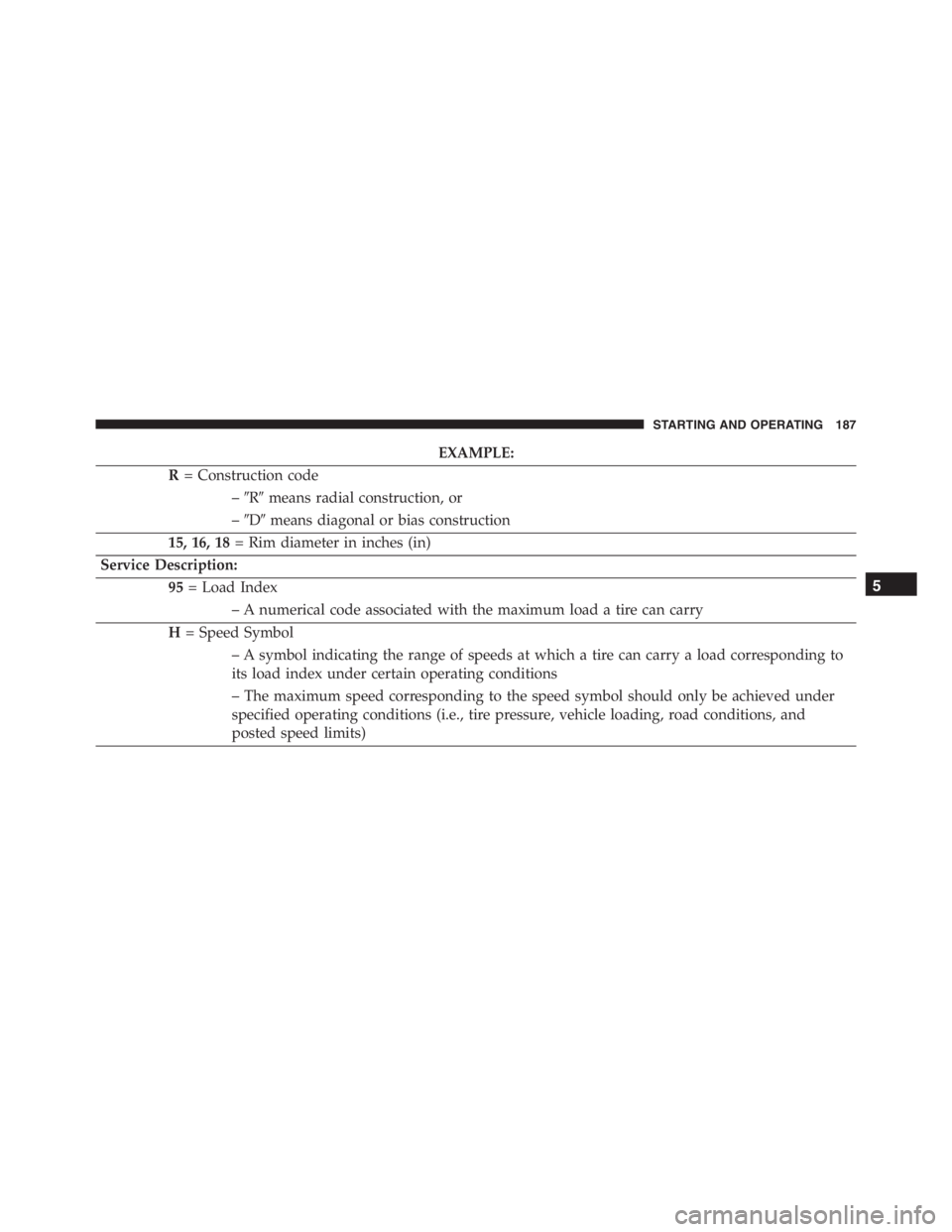
EXAMPLE:
R= Construction code
–�R�means radial construction, or
–�D�means diagonal or bias construction
15, 16, 18= Rim diameter in inches (in)
Service Description:
95= Load Index
– A numerical code associated with the maximum load a tire can carry
H= Speed Symbol
– A symbol indicating the range of speeds at which a tire can carry a load corresponding to
its load index under certain operating conditions
– The maximum speed corresponding to the speed symbol should only be achieved under
specified operating conditions (i.e., tire pressure, vehicle loading, road conditions, and
posted speed limits)
5
STARTING AND OPERATING 187
Page 202 of 348

Tire Repair
If your tire becomes damaged, it may be repaired if it
meets the following criteria:
•The tire has not been driven on when flat.
•The damage is only on the tread section of your tire
(sidewall damage is not repairable).
•The puncture is no greater thana¼ofaninch (6 mm).
Consult an authorized tire dealer for tire repairs and
additional information.
Damaged Run Flat tires, or Run Flat tires that have
experienced a loss of pressure should be replaced imme-
diately with another Run Flat tire of identical size and
service description (Load Index and Speed Symbol).Tire Types
All Season Tires — If Equipped
All Season tires provide traction for all seasons (spring,
summer, fall and winter). Traction levels may vary be-
tween different all season tires. All season tires can be
identified by the M+S, M&S, M/S or MS designation on
the tire sidewall. Use all season tires only in sets of four;
failure to do so may adversely affect the safety and
handling of your vehicle.
Summer Or Three Season Tires — If Equipped
Summer tires provide traction in both wet and dry
conditions, and are not intended to be driven in snow or
on ice. If your vehicle is equipped with summer tires, be
aware these tires are not designed for winter or cold
driving conditions. Install winter tires on your vehicle
when ambient temperatures are less than 40°F (5°C) or if
roads are covered with ice or snow. For more informa-
tion, contact an authorized dealer.
200 STARTING AND OPERATING

Setup Menu
The menu comprises a se")