2015 NISSAN ROGUE SELECT fuel
[x] Cancel search: fuelPage 88 of 322
WARNING
.If the light does not illuminate with
the ignition switch turned ON, have
the vehicle checked by a NISSAN
dealer as soon as possible.
. If the light illuminates while driving,
avoid sudden steering maneuvers or
abrupt braking, reduce vehicle
speed, pull off the road to a safe
location and stop the vehicle as
soon as possible. Driving with un-
der-inflated tires may permanently
damage the tires and increase the
likelihood of tire failure. Serious
vehicle damage could occur and
may lead to an accident and could
result in serious personal injury.
Check the tire pressure for all four
tires. Adjust the tire pressure to the
recommended COLD tire pressure
shown on the Tire and Loading
Information label to turn the low
tire pressure warning light OFF. If
the light stays on after adjusting the
tire pressure and driving over 16
MPH (25 km/h) , have the system
checked by a NISSAN dealer. If you
have a flat tire, replace it with a spare tire as soon as possible.
. When a spare tire is mounted or a
wheel is replaced, the TPMS will not
function and the low tire pressure
warning light will flash for approxi-
mately 1 minute. The light will
remain on after 1 minute. Contact
your NISSAN dealer as soon as
possible for tire replacement and/
or system resetting.
. Replacing tires with those not ori-
ginally specified by NISSAN could
affect the proper operation of the
TPMS.
CAUTION
.The TPMS is not a substitute for the
regular tire pressure check. Be sure
to check the tire pressure regularly.
. If the vehicle is being driven at
speeds of less than 16 MPH (25
km/h) , the TPMS may not operate
correctly.
. Be sure to install the specified size
of tires to the front and rear.
Master warning light
When the ignition switch is in the ON position,
the master warning light illuminates if any of the
following are displayed on the vehicle informa-
tion display.
. Low fuel warning
. Parking brake release warning
. Door open warning
. Lift gate open warning
. Loose fuel cap warning
. Check tire pressure warning
. Setting menu operation warning
. Extended storage fuse warning (if so
equipped)
See “Vehicle information display” (P.2-17) .
Seat belt warning light
The light and chime remind you to fasten seat
belts. The light illuminates whenever the ignition
switch is turned to the ON position, and will
remain illuminated until the driver’s seat belt is
fastened. At the same time, the chime will sound
for about 6 seconds unless the driver’s seat belt
is securely fastened.
The seat belt warning light for the front
passenger will illuminate if the seat belt is not
fastened when the front passenger’s seat is
Instruments and controls2-13
Page 90 of 322
Front passenger air bag status light
The front passenger air bag status light will be lit
and the passenger front air bag will be OFF
depending on how the front passenger seat is
being used.
For front passenger air bag status light opera-
tion, see “NISSAN Advanced Air Bag System
(front seats)” (P.1-47) of this manual.
High beam indicator light
This light illuminates when the headlight high
beam is on and goes out when the low beam is
selected.
Malfunction Indicator Light (MIL)
If the malfunction indicator light illuminates
steady or blinks while the engine is running, it
may indicate a potential emission control and/or
Continuously Variable Transmission (CVT) mal-
function.
The malfunction indicator light may also illumi-
nate steady if the fuel-filler cap is loose or
missing, or if the vehicle runs out of fuel. Check
to make sure the fuel-filler cap is installed and
closed tightly, and that the vehicle has at least 3
US gallons (11.4 liters) of fuel in the fuel tank.
After a few driving trips, the
light should
turn off if no other potential emission control system malfunction exists.
If this indicator light remains on for 20 seconds
and then blinks for 10 seconds when the engine
is not running, it indicates that the vehicle is not
ready for an emission control system inspection/
maintenance test. (See “Readiness for Inspec-
tion/Maintenance (I/M) test” (P.9-26) .)
Operation:
The malfunction indicator light will illuminate in
one of two ways:
.
Malfunction indicator light illuminated steady
— An emission control system and/or CVT
malfunction has been detected. Check the
fuel-filler cap if the LOOSE FUEL CAP
warning appears in the vehicle information
display. If the fuel-filler cap is loose or
missing, tighten or install the cap and
continue to drive the vehicle. The
light
should turn off after a few driving trips. If the
light does not turn off after a few driving
trips, have the vehicle inspected by a
NISSAN dealer. You do not need to have
your vehicle towed to the dealer.
. Malfunction indicator light blinking — An
engine misfire has been detected which may
damage the emission control system.
To reduce or avoid emission control system
damage: — Do not drive at speeds above 45 MPH
(72 km/h) .
— Avoid hard acceleration or deceleration.
— Avoid steep uphill grades.
— If possible, reduce the amount of cargo being hauled or towed.
The malfunction indicator light may stop
blinking and remain illuminated.
Have the vehicle inspected by a NISSAN
dealer. You do not need to have your vehicle
towed to the dealer.
CAUTION
Continued vehicle operation without
having the emission control system
and/or CVT system checked and re-
paired as necessary could lead to poor
driveability, reduced fuel economy, and
possible damage to the emission con-
trol system.
Instruments and controls2-15
Page 94 of 322
INDICATORS FOR OPERATION
The design of the warnings and alerts may differ
depending on the model.
1. Door open warning
This warning appears if any of the doors are
open or not closed securely. The vehicle icon
indicates which door is open on the display.
2. Lift gate open warning
This warning appears if the lift gate is open or
not closed securely. When theswitch is
pushed, the lift gate open warning turns off.
3. Loose fuel cap warning
This warning appears when the fuel-filler cap is
not tightened correctly after the vehicle has
been refueled. (See “Fuel-filler cap” (P.3-11) .)
4. Check tire pressure warning
This warning appears when the low tire pressure
warning light in the meter illuminates and low tire
pressure is detected. The warning appears each
time the ignition switch is placed in the ON
position as long as the low tire pressure warning
light remains illuminated. If this warning appears,
stop the vehicle and adjust the tire pressure to
the recommended COLD tire pressure shown
on the Tire and Loading Information label. The
check tire pressure warning turns off after a period of time. (See “Low tire pressure warning
light” (P.2-12) and “Tire Pressure Monitoring
System (TPMS)” (P.5-3) .)
5. Parking brake release warning
This warning appears when the vehicle speed is
above 4 MPH (7 km/h) and the parking brake is
applied.
6. Setting menu operation warning
The warning appears when you try to operate
the setting menu while driving. The setting menu
can only be entered when the vehicle is
stationary.
7. Low outside temperature warning
This warning appears if the outside temperature
drops below 378F(3
8C) with the ignition switch
in the ON position. The outside temperature
display flashes at the same time. These warning
features can be turned off. (See “Trip computer”
(P.2-21) .)
8. Low fuel warning
This warning appears when the fuel level in the
tank is getting low. Refuel as soon as it is
convenient, preferably before the fuel gauge
reaches the empty (0) position.
There is a small reserve of fuel remaining
in the tank when the fuel gauge reaches
the empty (0) position.
9. Driver alert
This warning appears when the previously set
time for a break is reached. You can set the time
for up to 6 hours in the setting menu. (See “Trip
computer” (P.2-21).)
10. Cruise control indicator (if so
equipped)
The cruise main switch indicator (CRUISE) is
displayed when the cruise control main switch is
pushed. When the main switch is pushed again,
the CRUISE indicator disappears. When the
CRUISE indicator is displayed, the cruise
control system is operational.
The cruise control set indicator (SET) is
displayed while the vehicle speed is controlled
by the cruise control system. If the SET indicator
blinks while the engine is running, it may indicate
that the cruise control system is not functioning
properly. Have the system checked by a
NISSAN dealer.
For more details, see “Cruise control” (P.5-17) .
11. Extended storage fuse warning (if so
equipped)
This warning may appear if the extended storage
fuse switch is not pushed in (switched on) .
When this warning appears, push in (switch on)
the extended storage fuse switch to turn off the
Instruments and controls2-19
Page 96 of 322
replacement indicator as a guide only
and always perform regular tire checks.
Failure to perform regular tire checks,
including tire pressure checks could
result in tire failure. Serious vehicle
damage could occur and may lead to a
collision, which could result in serious
personal injury or death.
3. “Other” indicator
This indicator appears when the customer set
distance comes for checking or replacing
maintenance items other than the engine oil, oil
filter and tires. Other maintenance items can
include such things as air filter or tire rotation.
You can set or reset the distance for checking or
replacing the items. (See “Trip computer” (P.2-
21) .) For scheduled maintenance items and
intervals, see your NISSAN Service and Main-
tenance Guide.
SIC4551
TRIP COMPUTER
To operate the trip computer, use the*Aswitch.
When the ignition switch is in the ON position,
modes of the trip computer can be selected by
pushing the
switch*Abriefly.
Each time the
switch*Ais pushed, the
display will change as follows:
Fuel Economy ?Average speed ?Driving
distance ?Elapsed time ?Range (distance to
empty) (dte) ?Settings
. When the
switch*Ais pushed and
held for less than 3 seconds, the selected
item can be reset except for “Range”, “Current fuel consumption” and “Settings”.
. When the
switch*Ais pushed and
held for more than 3 seconds, all the items
on the display can be reset except for
“Current fuel consumption”, “Settings”,
“Range” and “TRIP A”.
Instruments and controls2-21
Page 97 of 322
2-22Instruments and controls
SIC4541Example*
*: The display unit can be converted or varies
depending on the vehicle.
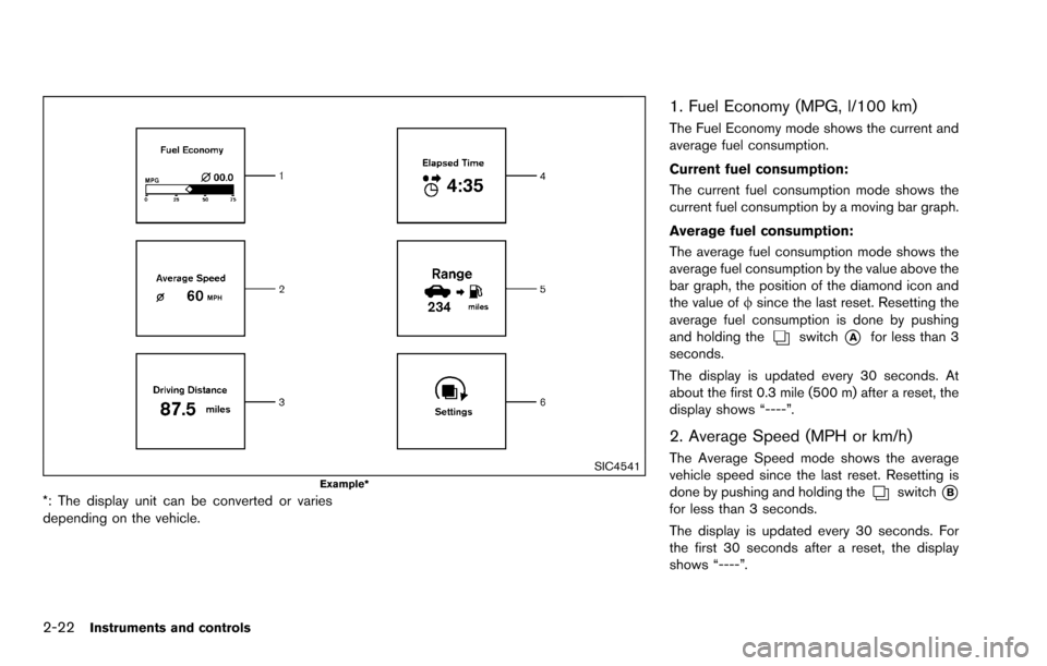
1. Fuel Economy (MPG, l/100 km)
The Fuel Economy mode shows the current and
average fuel consumption.
Current fuel consumption:
The current fuel consumption mode shows the
current fuel consumption by a moving bar graph.
Average fuel consumption:
The average fuel consumption mode shows the
average fuel consumption by the value above the
bar graph, the position of the diamond icon and
the value offsince the last reset. Resetting the
average fuel consumption is done by pushing
and holding the
switch*Afor less than 3
seconds.
The display is updated every 30 seconds. At
about the first 0.3 mile (500 m) after a reset, the
display shows “----”.
2. Average Speed (MPH or km/h)
The Average Speed mode shows the average
vehicle speed since the last reset. Resetting is
done by pushing and holding the
switch*Bfor less than 3 seconds.
The display is updated every 30 seconds. For
the first 30 seconds after a reset, the display
shows “----”.
Page 98 of 322
3. Driving Distance (miles or km)
The Driving Distance mode shows the distance
driven since the last reset. The driving distance
can be reset by pushing and holding the
switch*Afor less than 3 seconds.
4. Elapsed Time
The Elapsed Time mode shows the time since
the last reset. The displayed time can be reset
by pushing and holding the
switch*Afor
less than 3 seconds.
5. Range (distance to empty) (dte —
miles or km)
The distance to empty (dte) mode provides you
with an estimation of the distance that can be
driven before refueling. The dte is constantly
being calculated based on the amount of fuel in
the fuel tank and the actual fuel consumption.
The display is updated every 30 seconds.
The dte mode includes a low range warning
feature. If the fuel level is low, the warning is
displayed on the screen.
When the fuel level drops even lower, the dte
display will change to “----”.
. If the amount of fuel added is small, the
display just before the ignition switch is
turned to the “OFF” position may continue to
be displayed. .
When driving uphill or rounding curves, the
fuel in the tank shifts, which may momenta-
rily change the display.
JVI1227X
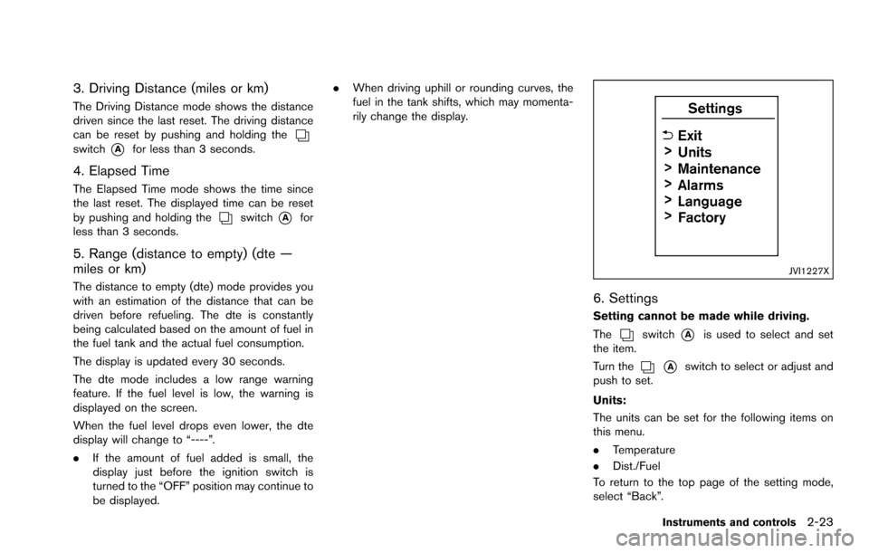
6. Settings
Setting cannot be made while driving.
The
switch*Ais used to select and set
the item.
Turn the
*Aswitch to select or adjust and
push to set.
Units:
The units can be set for the following items on
this menu.
. Temperature
. Dist./Fuel
To return to the top page of the setting mode,
select “Back”.
Instruments and controls2-23
Page 120 of 322
3 Pre-driving checks and adjustments
Keys ........................................................................\
...................... 3-2NISSAN Vehicle Immobilizer System keys ................... 3-2
Doors ........................................................................\
.................... 3-3
Locking with key .................................................................. 3-3
Locking with inside lock knob .......................................... 3-3
Locking with power door lock switch ............................ 3-4
Automatic door locks ......................................................... 3-4
Child safety rear door lock ............................................... 3-5
Remote keyless entry system ................................................ 3-5 How to use remote keyless entry system ..................... 3-6
Hood ........................................................................\
..................... 3-9 Lift gate ........................................................................\
............ 3-10
Lift gate release .............................................................. 3-10
Fuel-filler door ........................................................................\
3-11
Opening the fuel-filler door ......................................... 3-11
Fuel-filler cap .................................................................. 3-11
Steering wheel ....................................................................... 3-13
Tilt operation ................................................................... 3-13
Sun visors ........................................................................\
........ 3-13
Mirrors ........................................................................\
.............. 3-14 Inside mirror ..................................................................... 3-14
Outside mirrors ............................................................... 3-14
Vanity mirror ..................................................................... 3-15
Page 130 of 322
SPA2415
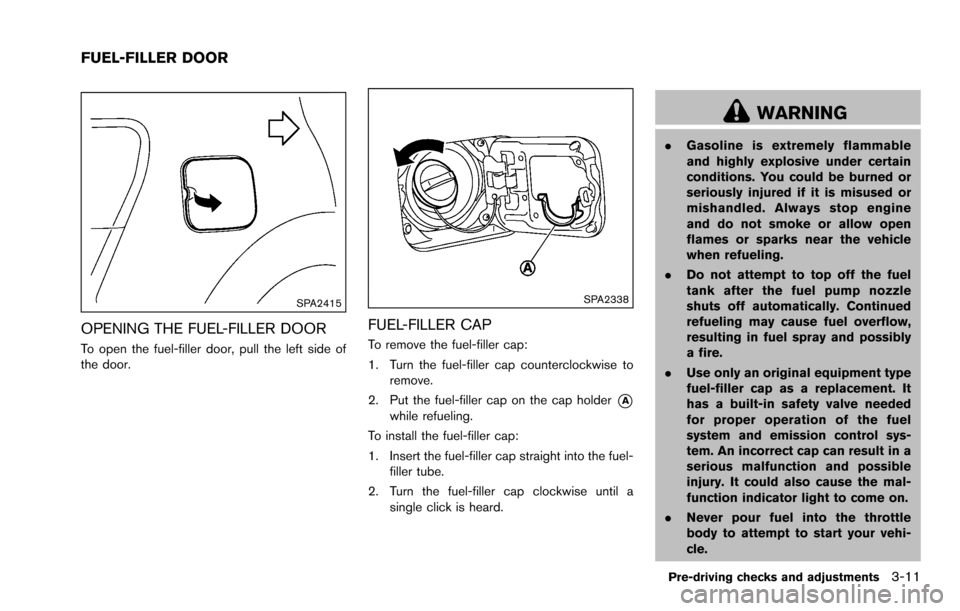
OPENING THE FUEL-FILLER DOOR
To open the fuel-filler door, pull the left side of
the door.
SPA2338
FUEL-FILLER CAP
To remove the fuel-filler cap:
1. Turn the fuel-filler cap counterclockwise toremove.
2. Put the fuel-filler cap on the cap holder
*Awhile refueling.
To install the fuel-filler cap:
1. Insert the fuel-filler cap straight into the fuel- filler tube.
2. Turn the fuel-filler cap clockwise until a single click is heard.
WARNING
.Gasoline is extremely flammable
and highly explosive under certain
conditions. You could be burned or
seriously injured if it is misused or
mishandled. Always stop engine
and do not smoke or allow open
flames or sparks near the vehicle
when refueling.
. Do not attempt to top off the fuel
tank after the fuel pump nozzle
shuts off automatically. Continued
refueling may cause fuel overflow,
resulting in fuel spray and possibly
a fire.
. Use only an original equipment type
fuel-filler cap as a replacement. It
has a built-in safety valve needed
for proper operation of the fuel
system and emission control sys-
tem. An incorrect cap can result in a
serious malfunction and possible
injury. It could also cause the mal-
function indicator light to come on.
. Never pour fuel into the throttle
body to attempt to start your vehi-
cle.
Pre-driving checks and adjustments3-11
FUEL-FILLER DOOR