Page 247 of 293

CAUTION
●High-pressure halogen gas is sealed in-
side the bulb. The bulb may break if the
glass envelope is scratched or the bulb
is dropped.
● Aiming should not be necessary after
replacing the H4 bulb. When aiming ad-
justment is necessary, contact a
NISSAN dealer.
● Do not leave the headlight assembly
open without a bulb installed for a long
period of time. Dust, moisture, smoke,
etc. entering the headlight body may
affect bulb performance. Remove the
bulb from the headlight assembly just
before a replacement bulb is installed.
● Only touch the base when handling the
bulb. Never touch the glass envelope.
Touching the glass could significantly
affect bulb life and/or headlight
performance.
● Use the same number and wattage as
shown in the chart.
1. Disconnect the battery negative cable.
2. Disconnect the electrical connector
�Afrom
the rear end of the bulb. 3. Pull off the rubber cap
�B.
4. Push and turn the retaining pin
�Cto loosen
it.
5. Remove the headlight bulb. Do not shake or rotate the bulb when removing it.
6. Install the new bulb in the reverse order of removal.
Fog may temporarily form inside the lens of the
exterior lights in the rain or in a car wash. A
temperature difference between the inside and
the outside of the lens causes the fog. This is not
a malfunction. If large drops of water collect
inside the lens, contact a NISSAN dealer.
HEADLIGHT AIM
The aim of the headlights may require adjustment
when replacing the headlight assembly or when
the vehicle’s front body has been repaired. When
the adjustment is required, follow these proce-
dures, or have them adjusted by a NISSAN
dealer.
Before performing the headlights aim adjust-
ment:
● Check the pressure of all tires for the correct
inflation pressure.
● Check that the tools and spare tire are
stowed securely.
LDI2422
8-26Maintenance and do-it-yourself
Page 248 of 293
●Check that the fuel and lubricants levels are
filled to correct capacities.
● Unload all luggage and other items, which
may influence the vehicle’s height level.
● Load a weight on the driver’s seat that is
equivalent to the weight of a driver.
Stopping the vehicle
1. Park the vehicle on a level surface vertical to
the wall or screen to which the headlights
will be projected.
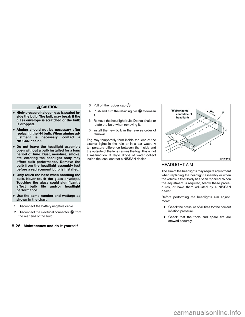
2. Move the vehicle close to the wall to deter- mine the point P as shown in the illustration.
The point P must be:
“H” is the distance between the headlight’s
center point to the level surface.
“WL” is the distance between the left and
right headlights’ centers.
3. Mark point P on the wall or screen. 4. Back up the vehicle 5,000 mm (197.0 in,
16.4 ft) straight away from the wall or
screen.
”L” is the distance between the wall or
screen to the vehicle’s front bumper.
5. Apply the parking brake.
LDI2423
Maintenance and do-it-yourself8-27
Page 249 of 293

Adjusting the headlight aim
Be sure that the vehicle is parked directly vertical
to the wall on which the headlights will be pro-
jected.1. Turn on the headlight low beam
2. Open the hood.
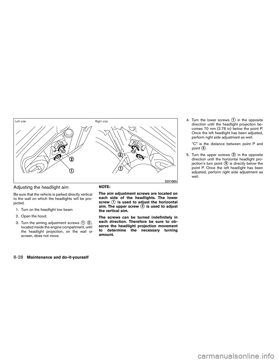
3. Turn the aiming adjustment screws
�1�2,
located inside the engine compartment, until
the headlight projection, on the wall or
screen, does not move. NOTE:
The aim adjustment screws are located on
each side of the headlights. The lower
screw
�1is used to adjust the horizontal
aim. The upper screw
�2is used to adjust
the vertical aim.
The screws can be turned indefinitely in
each direction. Therefore be sure to ob-
serve the headlight projection movement
to determine the necessary turning
amount. 4. Turn the lower screws
�1in the opposite
direction until the headlight projection be-
comes 70 mm (2.76 in) below the point P.
Once the left headlight has been adjusted,
perform right side adjustment as well.
”C” is the distance between point P and
point
�3.
5. Turn the upper screws
�2in the opposite
direction until the horizontal headlight pro-
jection’s turn point
�3is directly below the
point P. Once the left headlight has been
adjusted, perform right side adjustment as
well.
SDI1665
8-28Maintenance and do-it-yourself
Page 288 of 293

Fuel-filler lid and cap............3-11
Fuel gauge ...................2-5
Fuel octane rating ...............9-5
Fuel gauge .....................2-5
Fuses.......................8-20
Fusible links ...................8-21
G
Gascap .....................3-11
Gauge Fuel gauge ...................2-5
Odometer ...................2-4
Speedometer .................2-3
Tachometer ..................2-4
Trip computer .................2-5
Trip odometer .................2-4
General maintenance ...............8-2
Glovebox.....................2-23
H
Hands-free phone system, Bluetooth® ....4-46
Hazard warning flasher switch ..........6-2
Headlight and turn signal switch ........2-17
Headlightcontrolswitch ............2-17
Headlights....................8-25
Head restraints ..................1-6
Heater Heater and air conditioner controls . .4-7, 4-15
Heater operation ............4-9,4-17
Hood release ...................3-9
Horn .......................2-20 I
Ignition switch ...................5-5
Immobilizer system ..........2-13,3-2,5-7
Important vehicle information label .......9-11
Increasing fuel economy .............5-17
Indicator lights and audible reminders
(See warning/indicator lights and audible
reminders) .....................2-7
Inside mirror ...................3-14
Instrument brightness control ..........2-18
Instrument panel ...............0-6,2-2
Instrument panel dimmer switch ........2-18
Intelligent Key system Remote keyless entry operation .......3-7
Interiorlight....................2-27
iPod® Player ...................4-42
ISOFIX child restraints .............1-20
J
Jump starting ...............6-10,8-15
K
Key.........................3-2
Key fob battery replacement ..........8-24
Keyless entry With Intelligent Key system
(See Intelligent Key system) .........3-7
Keyless entry system
(See remote keyless entry system) ........3-6 L
Labels Air conditioner specification label .....9-12
C.M.V.S.S. certification label ........9-11
Emission control information label .....9-11
Engine serial number ............9-11
Tire and Loading Information label .....9-12
Vehicle identification number (VIN) plate . .9-10
Warning labels (for SRS) ..........1-54
LATCH (Lower Anchors and Tethers for CHildren)
System ......................1-20
License plate Installing the license plate ..........9-12
Light A
irbagwarninglight.........1-55,2-10
Brake light (See stop light) .........8-29
Bulb check/instrument panel .........2-7
Bulb replacement ..............8-29
Charge warning light .............2-8
Foglights...................8-29
Headlightandturnsignalswitch......2-17
Headlight control switch ..........2-17
Headlights..................8-25
Interior light ..................2-27
Lightbulbs..................8-25
Low windshield-washer fluid warning
light.......................2-9
Passenger air bag and status light .....1-49
Security indicator light ............2-11
Warning/indicator lights and audible
reminders ...................2-7
Lock Child safety rear door lock ..........3-5
Doorlocks...................3-3
10-3