2015 MITSUBISHI OUTLANDER steering
[x] Cancel search: steeringPage 186 of 446
Forward Collision Mitigation System (FCM) (if so equipped)
Features and controls 5-109
5
N00577800032
This switch is used to turn on or off the FCM and also to select the distance which will trig-ger the forward collision warning function.
• When a vehicle ahea
d or an oncoming
vehicle is splashing wa
ter, snow or dirt.
When the system recognizes driver’s steering or accelerati
ng actions as evasive
actions to avoid collision, FCM controland alarm functions
may be canceled.
In certain situations,
though there is little
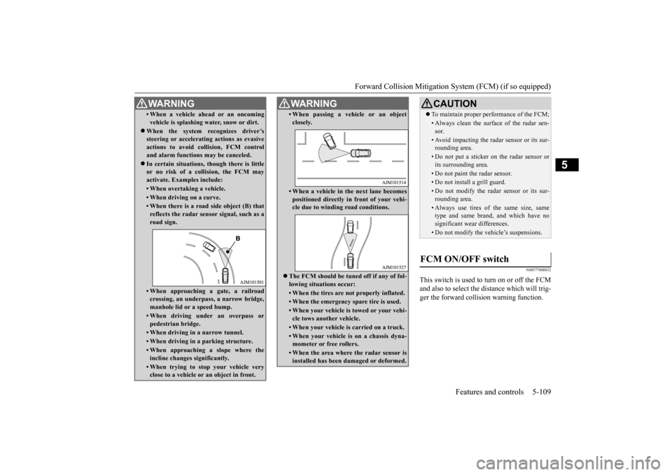
or no risk of a collision, the FCM may activate. Examples include: • When overtaking a vehicle.• When driving on a curve.• When there is a road
side object (B) that
reflects the radar sensor signal, such as aroad sign.• When approaching a gate, a railroadcrossing, an underpa
ss, a narrow bridge,
manhole lid or
a speed bump.
• When driving unde
r an overpass or
pedestrian bridge.• When driving in
a narrow tunnel.
• When driving in a parking structure.• When approaching a slope where the incline changes
significantly.
• When trying to stop your vehicle very close to a vehicle or
an object in front.
WA R N I N G
• When passing a vehicle or an object closely.• When a vehicle in the next lane becomespositioned directly in
front of your vehi-
cle due to winding road conditions.
The FCM should be tuned off if any of fol- lowing situations occur:• When the tires are not properly inflated. • When the emergency spare tire is used.• When your vehicle is
towed or your vehi-
cle tows another vehicle.• When your vehicle is carried on a truck.• When your vehicle is on a chassis dyna- mometer or free rollers.• When the area where the radar sensor isinstalled has been damaged or deformed.WA R N I N G
CAUTION To maintain proper performance of the FCM;• Always clean the surface of the radar sen- sor.• Avoid impacting the radar sensor or its sur-rounding area.• Do not put a sticker on the radar sensor orits surrounding area.• Do not paint the radar sensor.• Do not install a grill guard.• Do not modify the radar sensor or its sur- rounding area.• Always use tires of the same size, sametype and same brand,
and which have no
significant wear differences.• Do not modify the vehicle’s suspensions.
FCM ON/OFF switch
BK0211800US.book 109 ページ 2014年3月12日 水曜日 午後2時42分
Page 194 of 446
Tire pressure monitoring system
Features and controls 5-117
5
allow the TPMS to continue to function prop- erly.
N00532801511
1. If the tire pressure monitoring systemwarning light illumi
nates, avoiding hard
braking, sharp steering maneuvers and high speeds. You should stop and adjust the tires to the proper inflation pressure as soon as possible. Adjust the spare tire atthe same time. Refer to “Tires” on page 9-14.
2. If the tire pressure monitoring system warning light remains illuminated afteryou have been driving for about 20 min- utes after you adjust the tire inflation pres- sure, one or more of the tires may have apuncture. Inspect the tire and if it has a puncture, have it repaired by an autho- rized Mitsubishi Motors dealer as soon aspossible.
The tire pressure monitoring system may not work normally in the following circum- stances: A wireless facility or device using the same frequency is near the vehicle. Snow or ice is stuck inside the fenders and/or on the wheels. The tire inflation pres
sure sensor’s battery
is dead. Wheels other than Mitsubishi genuine wheels are being used. Wheels that are not fitted with tire infla- tion pressure sensors are being used. Wheels whose ID codes are not memo- rized by the vehicle are used. Compact spare tire is fitted as a road wheel.
If the warning light / display illuminates while driving
NOTE
In addition, the warni
ng display is displayed
on the information screen in the multi-infor- mation display. When inspecting or adjusting the tire pres- sure, do not apply excessive force to the valve stem to avoid breakage. After inspecting or adju
sting the tire pres-
sure, always reinstall the valve cap on thevalve stem. Without the valve cap, dirt or moisture could get into the valve, resulting in damage to thetire inflation pressure sensor. Do not use metal valve caps, which may cause a metal reaction, resulting in corrosion and damage of the tire inflation pressure sen- sors.
Once adjustments have
been made, the warn-
ing light will go off after a few minutes ofdriving.WA R N I N G If the warning light / display illuminates while you are driving,
avoid hard braking,
sharp steering maneuvers and high speeds.Driving with an under-inflated tire adversely affects vehicle performance and can result in an accident.CAUTION If a tire has a puncture,
replace that tire with
the spare tire. Driving on a punctured tirecould lead to an accident. The warning light / di
splay may not illumi-
nate immediately in the
event of a tire blow-
out or rapid leak.NOTE
NOTE
To avoid the risk of da
mage to the tire infla-
tion pressure sensors, have any puncturedtire repaired by an authorized MitsubishiMotors dealer. If the tir
e repair is not done by
an authorized Mitsubishi Motors dealer, it is not covered by your warranty. Do not use an aerosol puncture-repair spray on any tire.Such a spray could damage the tire inflation pressure sensors. Have any puncture repaired by an authorizedMitsubishi Motors dealer.
BK0211800US.book 117 ページ 2014年3月12日 水曜日 午後2時42分
Page 229 of 446
Indicator light, warning light, and information screen display list (multi information display - Type 1) 5-152 Features and controls
5
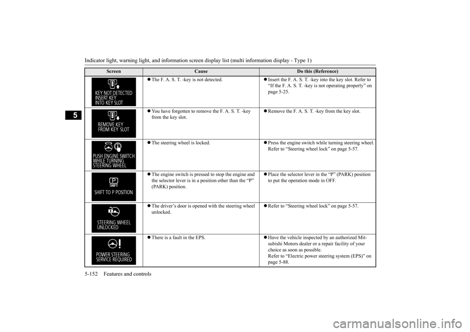
The F. A. S. T. -key is not detected.
Insert the F. A. S. T. -key
into the key slot. Refer to
“If the F. A. S. T. -key is not operating properly” on page 5-25.
You have forgotten to remove the F. A. S. T. -key from the key slot.
Remove the F. A. S. T. -key from the key slot.
The steering wheel is locked.
Press the engine switch while turning steering wheel. Refer to “Steering wheel lock” on page 5-57.
The engine switch is presse
d to stop the engine and
the selector lever is in a
position other than the “P”
(PARK) position.
Place the selector lever in the “P” (PARK) position to put the operation mode in OFF.
The driver’s door is opened with the steering wheel unlocked.
Refer to “Steering wheel lock” on page 5-57.
There is a fault in the EPS.
Have the vehicle inspected by an authorized Mit- subishi Motors dealer or
a repair facility of your
choice as soon as possible. Refer to “Electric power steering system (EPS)” on page 5-88.
Screen
Cause
Do this (Reference)
BK0211800US.book 152 ページ 2014年3月12日 水曜日 午後2時42分
Page 231 of 446
Indicator light, warning light, and information screen display list (multi information display - Type 1) 5-154 Features and controls
5
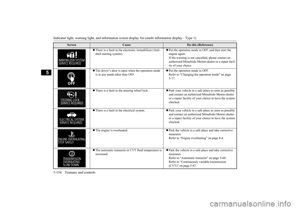
There is a fault in the electronic immobilizer (Anti- theft starting system).
Put the operation mode in OFF, and then start the engine again.If the warning is not cancel
led, please contact an
authorized Mitsubishi Motors dealer or a repair facil- ity of your choice.
The driver’s door is open when the operation mode is in any mode other than OFF.
Put the operation mode in OFF. Refer to “Changing the operation mode” on page 5-17.
There is a fault in the steering wheel lock.
Park your vehicle in a safe place as soon as possible and contact an authorized
Mitsubishi Motors dealer
or a repair facility of your
choice to have the system
checked.
There is a fault in the electrical system.
Park your vehicle in a safe place as soon as possible and contact an authorized
Mitsubishi Motors dealer
or a repair facility of your
choice to have the system
checked.
The engine is overheated.
Park the vehicle in a safe place and take corrective measures. Refer to “Engine overheating” on page 8-4.
The automatic transaxle or CVT fluid temperature is increased.
Park the vehicle in a safe place and take corrective measures. Refer to “Automatic tr
ansaxle” on page 5-60.
Refer to “Continuously
variable transmission
(CVT)” on page 5-67.
Screen
Cause
Do this (Reference)
BK0211800US.book 154 ページ 2014年3月12日 水曜日 午後2時42分
Page 242 of 446
Indicator and warning light package (multi information display - Type 2)
Features and controls 5-165
5
N00519801875
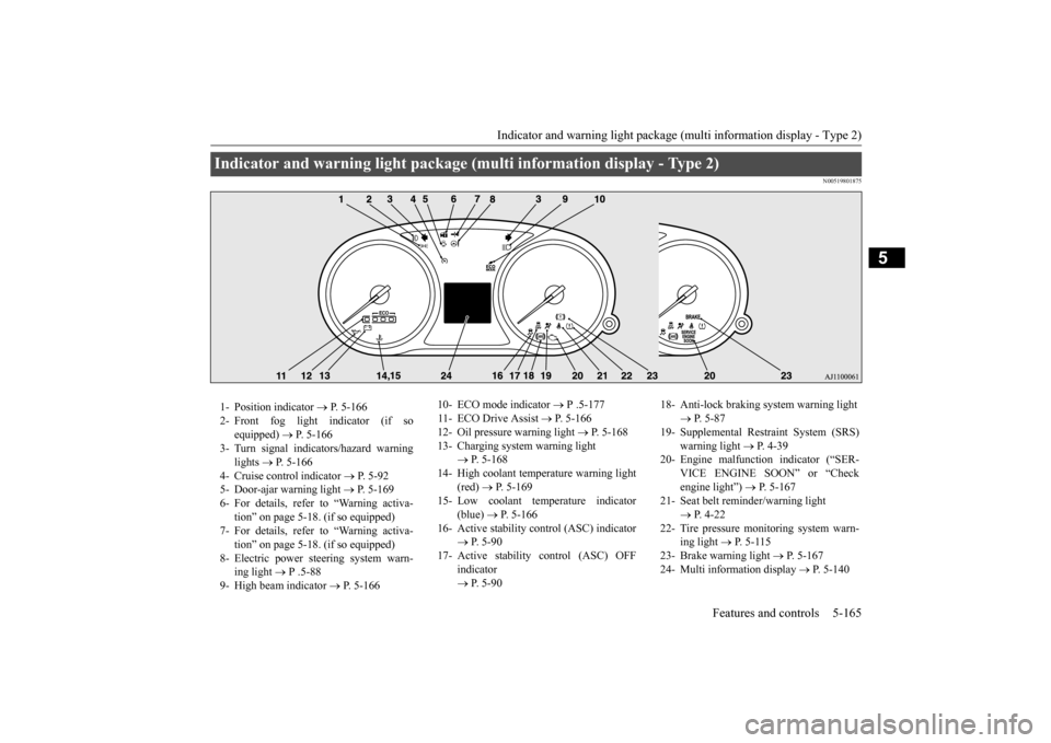
Indicator and warning light package (mu
lti information display - Type 2)
1- Position indicator
P. 5-166
2- Front fog light indicator (if so
equipped)
P. 5-166
3- Turn signal indicators/hazard warning
lights
P. 5-166
4- Cruise control indicator
P. 5-92
5- Door-ajar warning light
P. 5-169
6- For details, refer to “Warning activa-
tion” on page 5-18. (if so equipped)
7- For details, refer to “Warning activa-
tion” on page 5-18. (if so equipped)
8- Electric power steering system warn-
ing light
P .5-88
9- High beam indicator
P. 5-166
10- ECO mode indicator
P .5-177
11- ECO Drive Assist
P. 5-166
12- Oil pressure warning light
P. 5-168
13- Charging system warning light
P. 5-168
14- High coolant temperature warning light
(red)
P. 5-169
15- Low coolant temperature indicator
(blue)
P. 5-166
16- Active stability control (ASC) indicator
P. 5 - 9 0
17- Active stability
control (ASC) OFF
indicator P. 5 - 9 0
18- Anti-lock braking system warning light
P. 5-87
19- Supplemental Restra
int System (SRS)
warning light
P. 4 - 3 9
20- Engine malfuncti
on indicator (“SER-
VICE ENGINE SOON” or “Check engine light”)
P. 5-167
21- Seat belt remi
nder/warning light
P. 4-22
22- Tire pressure monitoring system warn-
ing light
P. 5-115
23- Brake warning light
P. 5-167
24- Multi information display
P. 5-140
BK0211800US.book 165 ページ 2014年3月12日 水曜日 午後2時42分
Page 253 of 446
Headlight leveling swit
ch (if so equipped)
5-176 Features and controls
5
N00537101115
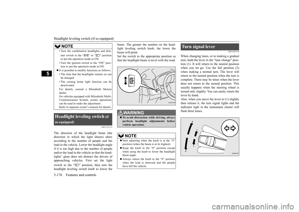
The direction of the headlight beam (the direction in which the light shines) altersaccording to the number of people and the load in the vehicle. Lo
wer the headlight angle
if it is too high due to the number of peopleand/or the load in the vehicle so that the head- lights’ glare does not distract the drivers of approaching vehicles. First set the light switch to the “ ” position, then turn the headlight leveling switch knob to lower the
beam. The greater the number on the head- light leveling switch knob, the lower thebeam will point. Set the switch to the appropriate position so that the headlight beam is level with the road.
N00522601529
When changing lanes, or to making a gradual turn, hold the lever in the “lane change” posi- tion (1). It will return
to the neutral position
when you let go. Use the full position (2) when making a normal turn. The lever will return to the neutral position when the turn iscomplete. There may be times when the lever does not return to the neutral position. This usually happens when the steering wheel is turned only slightly. You can easily return the lever by hand.Also, when you move the lever to (1) slightly then release it, the turn signal lights and the indicator light in the instrument cluster willflash three times.
• Turn the combination headlights and dim- mer switch to the “ ” or “ ” position or put the operation mode in ON. • Turn the ignition switch to the “ON” posi- tion or put the operation mode in ON.
It is possible to modify functions as follows: • The time that the he
adlights remain on can
be changed. • The coming home light function can be deactivated. For details, consult a Mitsubishi Motors dealer. On vehicles e
quipped with Mitsubishi Multi-
Communication System, screen operations can be used to ma
ke the adjustment.
Refer to separate owne
r’s manual for details.
Headlight leveling switch
(if
so equipped)
NOTE
WA R N I N G To avoid distraction while driving, always perform headlight
adjustments before
vehicle operation.NOTE
Start adjusting when the knob is at the “0” position (when the beam
is at its highest).
Keep the knob in the “0” position except when using the knob to lower the headlightbeam angle. Always return the knob to the “0” position when the load is removed and the people have left
the vehicle.
Turn signal lever
BK0211800US.book 176 ページ 2014年3月12日 水曜日 午後2時42分
Page 261 of 446

Horn switch 5-184 Features and controls
5
After about 15 to 20 minutes of operation, the system will shut off automatically.To switch the defogger OFF before 15 to 20 minutes have passed,
press the switch again.
The indicator light will
go out and the defog-
ger will turn off. If you need the defogger for more than 15 to 20 minutes, press the switch again. This willadd 15 to 20 more minutes.
N00523801195
To honk the horn, press around the “ ” markon the steering wheel.
N00563701066
The Link System takes co
ntrol of the devices
connected via the USB input terminal or the Bluetooth
® 2.0 interface; the system allows
the connected device to
be operated by using
the switches in the vehicle or voice com- mands. See the following secti
on for details on how
to operate. Refer to “Bluetooth
® 2.0 interface” on page
5-185.
CAUTION The rear window defogge
r is not designed to
melt snow. Remove any snow manually before using the rear window defogger. Use the rear window defogger only after the engine has started and
is running. Be sure to
turn the defogger switch off immediatelyafter the window is clea
r to save on battery
power.
Do not place stickers,
tape, or other items
that are attached with adhesive over the gridwires on the rear window. When cleaning the inside
rear window, use a
soft cloth and wipe lightly over the gridwires.NOTE
If your vehicle is e
quipped with door mirror
heater, mist can also be removed from the outside rearview mirror
s when the rear win-
dow defogger switch is
pressed. (Refer to
“Door mirror heater” on page 5-55.) It is possible to cha
nge the setting to make
the rear window defogger operate automati- cally when ambient temperature becomes low while the engine is running, even if youdo not push the rear window defogger switch. It operates automatically only once afterturning the ignition sw
itch to the “ON” posi-
tion or putting the ope
ration mode in ON.
If you choose this setting, the door mirrorheater (if so equipped) will also operateautomatically at the same time. For further informati
on, please contact your
authorized Mitsubishi Motors dealer.On vehicles equipped
with Mitsubishi Multi-
Communication System,
screen operations
can be used to make the adjustment.Refer to the separate owner’s manual for details.CAUTION
Horn switch Link System
(if so equipped)
BK0211800US.book 184 ページ 2014年3月12日 水曜日 午後2時42分
Page 263 of 446
Bluetooth® 2.0 interface (if so equipped) 5-186 Features and controls
5
Steering control sw
itch and microphone
P.5-186Voice recogni
tion function
P.5-187
Useful voice commands
P.5-188
Speaker enrollment function
P.5-190
Connecting the Bluetooth
® 2.0 interface and
the Bluetooth
® device
P.5-191
Operating a music player connected via Blue- tooth
® P.5-195
How to make or re
ceive hands-free calls
P.5-196Phonebook function
P.5-198
N00564001109
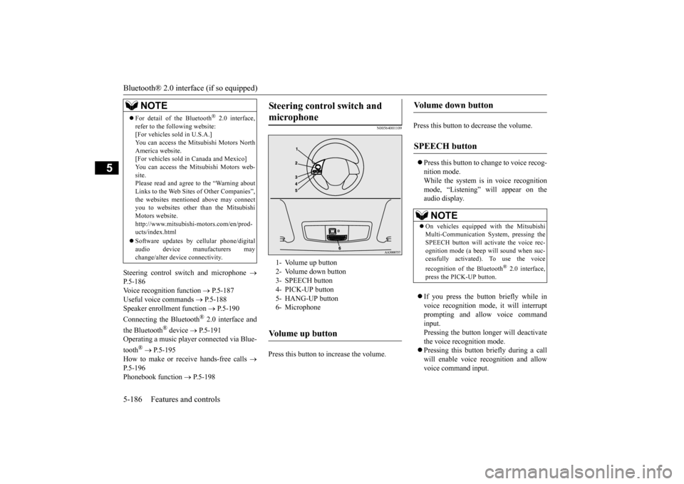
Press this button to increase the volume.
Press this button to decrease the volume. Press this button to ch
ange to voice recog-
nition mode.While the system is in voice recognition mode, “Listening” will appear on the audio display. If you press the button briefly while in voice recogniti
on mode, it will interrupt
prompting and allow voice commandinput. Pressing the button lo
nger will deactivate
the voice recognition mode. Pressing this button briefly during a call will enable voice
recognition and allow
voice command input.
For detail of the Bluetooth
® 2.0 interface,
refer to the following website: [For vehicles sold in U.S.A.] You can access the Mits
ubishi Motors North
America website. [For vehicles sold in
Canada and Mexico]
You can access the Mitsubishi Motors web-site. Please read and agree to the “Warning about Links to the Web Sites
of Other Companies”,
the websites mentione
d above may connect
you to websites other than the Mitsubishi Motors website.http://www.mitsubishi
-motors.com/en/prod-
ucts/index.html Software updates by cellular phone/digital audio device manufacturers may change/alter devi
ce connectivity.
NOTE
Steering control switch and microphone
1- Volume up button 2- Volume down button 3- SPEECH button4- PICK-UP button 5- HANG-UP button 6- MicrophoneVolume up button
Volume down button
SPEECH button
NOTE
On vehicles equipped
with the Mitsubishi
Multi-Communication System, pressing the SPEECH button will ac
tivate the voice rec-
ognition mode (a beep will sound when suc- cessfully activated)
. To use the voice
recognition of the Bluetooth
® 2.0 interface,
press the PICK-UP button.
BK0211800US.book 186 ページ 2014年3月12日 水曜日 午後2時42分