2015 MITSUBISHI OUTLANDER ECO mode
[x] Cancel search: ECO modePage 302 of 446
Floor mat
Driving safety 6-3
6
N00628600033
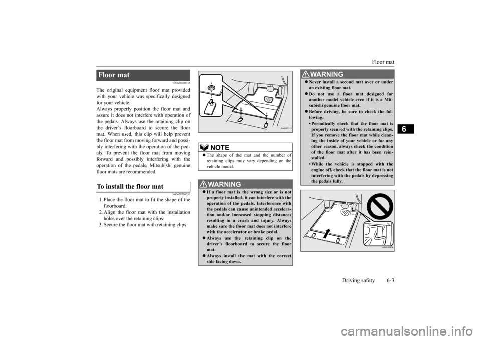
The original equipment floor mat provided with your vehicle was
specifically designed
for your vehicle.Always properly positio
n the floor mat and
assure it does not inte
rfere with operation of
the pedals. Always use the retaining clip onthe driver’s floorboard to secure the floor mat. When used, this clip will help prevent the floor mat from moving forward and possi- bly interfering with the operation of the ped- als. To prevent the floor mat from movingforward and possibly interfering with the operation of the pedals, Mitsubishi genuine floor mats are recommended.
N00628700050
1. Place the floor mat to fit the shape of thefloorboard.2. Align the floor mat with the installation holes over the retaining clips. 3. Secure the floor mat with retaining clips.Floor mat To install the floor mat
NOTE
The shape of the mat and the number of retaining clips may vary depending on the vehicle model.WA R N I N G If a floor mat is the
wrong size or is not
properly installed, it can interfere with theoperation of the pedals. Interference with the pedals can cause unintended accelera- tion and/or increased stopping distancesresulting in a cras
h and injury. Always
make sure the floor mat does not interfere with the accelerator or brake pedal. Always use the reta
ining clip on the
driver’s floorboard to secure the floormat. Always install the mat with the correct side facing down.
Never install a second mat over or under an existing floor mat. Do not use a floor mat designed for another model vehicle ev
en if it is a Mit-
subishi genuine floor mat. Before driving, be sure to check the fol- lowing:• Periodically check that the floor mat isproperly secured with the retaining clips.If you remove the fl
oor mat while clean-
ing the inside of you
r vehicle or for any
other reason, always
check the condition
of the floor mat afte
r it has been rein-
stalled.• While the vehicle is stopped with theengine off, check that
the floor mat is not
interfering with the pedals by depressingthe pedals fully.WA R N I N G
BK0211800US.book 3 ページ 2014年3月12日 水曜日 午後2時42分
Page 311 of 446
Trailer towing 6-12 Driving safety
6
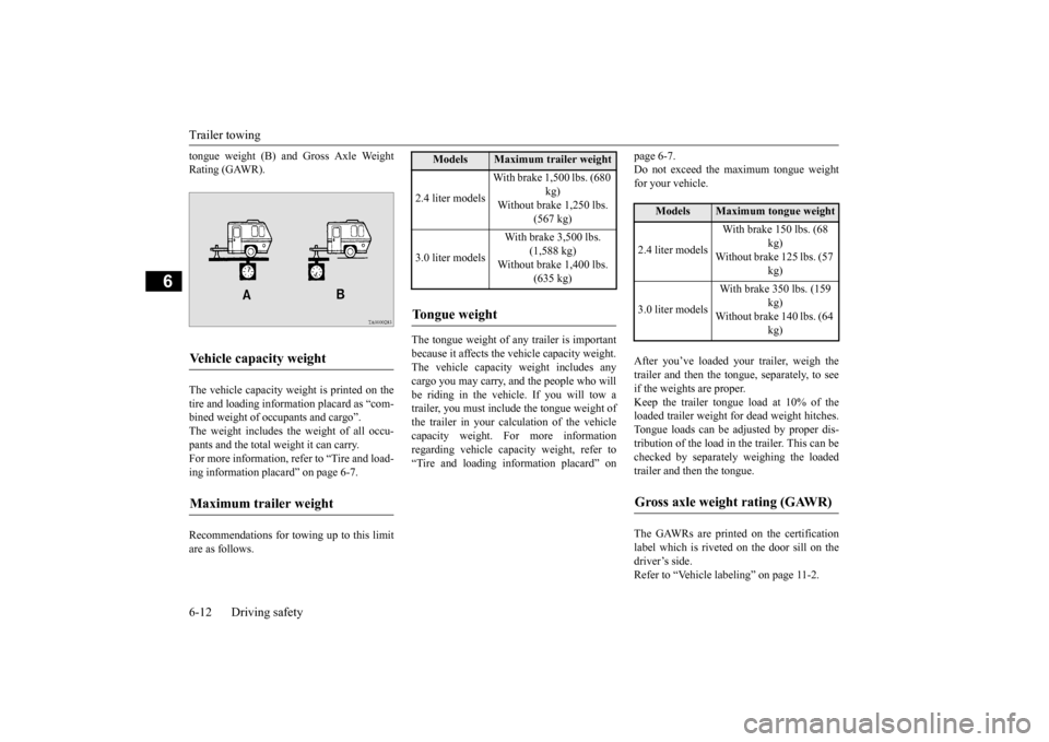
tongue weight (B) and Gross Axle Weight Rating (GAWR). The vehicle capacity weight is printed on the tire and loading inform
ation placard as “com-
bined weight of oc
cupants and cargo”.
The weight includes the weight of all occu- pants and the total weight it can carry.For more information, refer to “Tire and load- ing information plac
ard” on page 6-7.
Recommendations for towing up to this limit are as follows.
The tongue weight of any trailer is important because it affects the vehicle capacity weight. The vehicle capacity weight includes anycargo you may carry, and the people who will be riding in the vehicl
e. If you will tow a
trailer, you must include the tongue weight ofthe trailer in your calc
ulation of the vehicle
capacity weight. For more information regarding vehicle capa
city weight, refer to
“Tire and loading information placard” on
page 6-7. Do not exceed the maximum tongue weightfor your vehicle. After you’ve loaded your trailer, weigh the trailer and then the to
ngue, separately, to see
if the weights are proper. Keep the trailer tongue load at 10% of the loaded trailer weight fo
r dead weight hitches.
Tongue loads can be adjusted by proper dis- tribution of the load in the trailer. This can be checked by separately weighing the loadedtrailer and then the tongue. The GAWRs are printed on the certification label which is riveted on the door sill on the driver’s side. Refer to “Vehicle labeling” on page 11-2.
Vehicle capacity weight Maximum trailer weight
Models
Maximum trailer weight
2.4 liter models
With brake 1,500 lbs. (680
kg)
Without brake 1,250 lbs.
(567 kg)
3.0 liter models
With brake 3,500 lbs.
(1,588 kg)
Without brake 1,400 lbs.
(635 kg)
Tongue weight
Models
Maximum tongue weight
2.4 liter models
With brake 150 lbs. (68
kg)
Without brake 125 lbs. (57
kg)
3.0 liter models
With brake 350 lbs. (159
kg)
Without brake 140 lbs. (64
kg)
Gross axle weight rating (GAWR)
BK0211800US.book 12 ページ 2014年3月12日 水曜日 午後2時42分
Page 312 of 446
Trailer towing
Driving safety 6-13
6
Choose a proper hitch and ball, and make sure it is installed at a height that is compati- ble with the trailer.Use a good equalizing hitch which uniformly distributes the trailer tongue load throughout the frame. A safety chain must al
ways be used between
the towing vehicle and the trailer. Leave suf- ficient slack in the chain for turns. The chain
should cross under the trailer tongue to pre- vent the tongue from dropping to the groundin case it becomes damaged or separated. For correct safety chai
n procedures, consult
your authorized Mitsub
ishi Motors dealer.
Your vehicle will need service more often when you’re towing a trailer. Refer to “WAR- RANTY AND MAINTENANCE MAN-UAL”. Especially important in trailer operation are manual transaxle oil, automatic transaxle fluid, engine oi
l, rear axle oil, belt,
cooling system and brake system. Each of these is covered in this manual. For details, please refer to the “Vehicle careand maintenance” section. Check periodically to se
e that all hitch nuts
and bolts are tight.
Mitsubishi Motors recommends that any trailer having a total we
ight of 1,250 lbs (567
kg) or more (2400 models), 1,400 lbs (635kg) or more (3000 mode
ls) be equipped with
its own electric or surge-type brakes. If you choose electric br
akes, be sure they are
electrically actuated. Do not attempt to tap into your vehicle’s hydraulic system. No mat- ter how successful it
may seem, any attempt
to attach trailer brakes to your vehicle’s hydraulic system will lower braking effec- tiveness and create a potential hazard. Trailer lights and equipment must comply with federal, state,
and local regulations.
Check with your local
recreational vehicle
dealer for the requirements in your area, and use only equipment designed for your vehi-cle. Since lighting and wiring vary by trailer type and brand, you should have a qualified tech- nician install a suitable
connector between the
vehicle and the trailer. Improper equipment or installation can cause
damage to your vehi-
Trailer hitches
WA R N I N GIf you make any holes in the body of your vehicle for installing
a trailer hitch, be
sure to seal the holes later when you remove the hitch. If
you don’t seal them,
deadly carbon monoxide (CO) from your exhaust can enter your vehicle. Refer to “Exhaust system” on page 9-24.NOTE
Mitsubishi Motors recommends that sway control be used whenever you are towing, to improve towing stability. For further informati
on, please contact your
authorized Mitsubish
i Motors dealer.
Safety chains
CAUTIONNever tow a trailer wi
thout using a safety
chain securely attached to both the trailer and the vehicle. If the
coupling unit or hitch
ball experiences a probl
em, the trailer may
separate from
your vehicle.
Maintenance when trailer tow- ing
Trailer brakes Trailer lights
BK0211800US.book 13 ページ 2014年3月12日 水曜日 午後2時42分
Page 318 of 446
Vents
Comfort controls 7-3
7
N00736401605
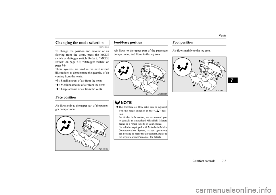
To change the position and amount of air flowing from the vents, press the MODE switch or defogger sw
itch. Refer to “MODE
switch” on page 7-9, “Defogger switch” on page 7-9. These symbols are used in the next severalillustrations to demonstr
ate the quantity of air
coming from the vents. : Small amount of air from the vents : Medium amount of air from the vents : Large amount of air from the vents Air flows only to the upper part of the passen- ger compartment.
Air flows to the upper part of the passenger compartment, and flows to the leg area.
Air flows mainly to the leg area.
Changing the mode selection Face position
Foot/Face position
NOTE
The foot/face air flow ratio can be adjusted with the mode selection in the “ ” posi- tion.For further information, we recommend you to consult an authorized Mitsubishi Motors dealer or a repair fa
cility of your choice.
On vehicles equipped
with Mitsubishi Multi-
Communication System, screen operations can be used to make
the adjustment. Refer to
the separate owner’s manual for details.
Foot position
BK0211800US.book 3 ページ 2014年3月12日 水曜日 午後2時42分
Page 319 of 446
Vents 7-4 Comfort controls
7
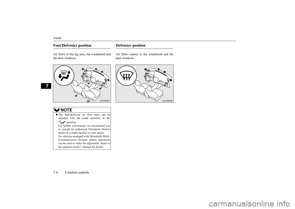
Air flows to the leg area, the windshield and the door windows.
Air flows mainly to the windshield and the door windows.
Foot/Defroster position
NOTE
The foot/defroster air flow ratio can be adjusted with the mode selection in the “ ” position. For further information, we recommend you to consult an authorized Mitsubishi Motors dealer or a repair fa
cility of your choice.
On vehicles e
quipped with Mitsubishi Multi-
Communication System, screen operations can be used to make the adjustment. Refer tothe separate owner’s manual for details.
Defroster position
BK0211800US.book 4 ページ 2014年3月12日 水曜日 午後2時42分
Page 322 of 446
Automatic climate cont
rol air conditioner
Comfort controls 7-7
7
N00736901189
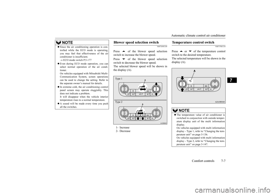
Press of the blower speed selection switch to increase the blower speed. Press of the blower speed selection switch to decrease the blower speed. The selected blower sp
eed will be shown in
the display (A).
N00737001334
Press or of the temperature controlswitch to the desired temperature. The selected temperature will be shown in the display (A).
NOTE
Since the air conditi
oning operation is con-
trolled while the ECO mode is operating,you may feel that effectiveness of the airconditioner is insufficient. ECO mode switch P.5-177
Even during ECO mode operation, you can select normal operati
on of the air condi-
tioner.On vehicles equipped
with Mitsubishi Multi-
Communication System,
screen operations
can be used to change the setting. Refer tothe separate owner’
s manual for details.
In extreme cold, the air conditioning control panel screen may operate sluggishly. This does not indicate a problem. It will disappear when
the vehicle interior
temperature rises to a normal temperature. A sound will be made every time you push all the switches.
Blower speed selection switch 1- Increase 2- DecreaseType 1 Type 2
Temperature control switch
NOTE
The temperature value of air conditioner is switched in conjunction
with outside temper-
ature display unit of the multi informationdisplay. On vehicles equipped with multi information display - Type 1, refer to “Changing the tem-perature unit” on page 5-136. On vehicles equipped with multi information display - Type 2, refer to “Changing the tem-perature unit” on page 5-147.
BK0211800US.book 7 ページ 2014年3月12日 水曜日 午後2時42分
Page 323 of 446
Automatic climate cont
rol air conditioner
7-8 Comfort controls
7
The above indicates the
factory settings. You
can personalize the air
selection switch and
air conditioning switch to match your per- sonal preferences.Contact your Mitsubishi
Motors dealer or a
repair facility of your
choice for assistance.
Refer to “Personalizi
ng the air conditioning
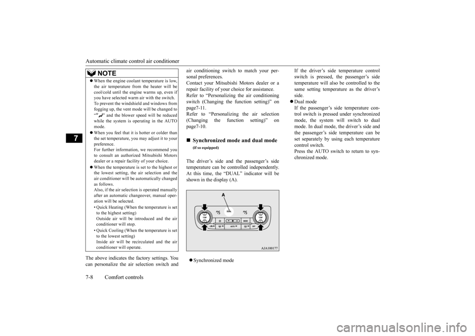
switch (Changing the function setting)” on page7-11. Refer to “Personalizing the air selection(Changing the function setting)” on page7-10. The driver’s side and the passenger’s side temperature can be controlled independently.At this time, the “
DUAL” indicator will be
shown in the display (A). Synchronized mode
If the driver’s side temperature control switch is pressed, the passenger’s sidetemperature will also be controlled to the same setting temperat
ure as the driver’s
side. Dual mode If the passenger’s side temperature con- trol switch is pressed under synchronizedmode, the system will switch to dual mode. In dual mode, the driver’s side and the passenger’s side
temperature can be
set separately by usi
ng each temperature
control switch.Press the AUTO switch to return to syn- chronized mode.
When the engine coolan
t temperature is low,
the air temperature from the heater will becool/cold until the engi
ne warms up, even if
you have selected warm
air with the switch.
To prevent the windshield and windows from fogging up, the vent mode
will be changed to
“ ” and the blower speed will be reduced while the system is operating in the AUTO mode. When you feel that it is hotter or colder than the set temperature, you may adjust it to yourpreference. For further information, we recommend you to consult an authorized Mitsubishi Motorsdealer or a repair fa
cility of your choice.
When the temperature is set to the highest or the lowest setting, the air selection and the air conditioner will be
automatically changed
as follows.Also, if the air selection is operated manually after an automatic ch
angeover, manual oper-
ation will be selected. • Quick Heating (When th
e temperature is set
to the highest setting)Outside air will be introduced and the air conditioner will stop. • Quick Cooling (When th
e temperature is set
to the lowest setting) Inside air will be recirculated and the airconditioner wi
ll operate.
NOTE
Synchronized mode and dual mode
(if so equipped)
BK0211800US.book 8 ページ 2014年3月12日 水曜日 午後2時42分
Page 325 of 446
Automatic climate cont
rol air conditioner
7-10 Comfort controls
7
automatically goes back
to the outside posi-
tion.If high cooling performanc
e is desired, or if
the outside air is dusty
or contaminated in
some way, use the
recirculat
ion position.
Switch to the outside position every now and then to keep the windows from fogging up.
N00712300023
You can change the following functions to match your preference.
Enable automatic air control: When the AUTO switch is pressed, the airselection switch will also be automatically controlled. Disable automatic air control: Even when the AUTO switch is pressed,the air selection switch will not be auto- matically controlled. Changing the settings Press the air selection switch for approxi- mately 10 seconds or longer. When the setting has changed, the systemwill beep and the indi
cator light will flash.
• When the setting has changed from enabled to disabled,
the system will beep
three times and the indicator light will flash three times. • When the setting has changed from dis-abled to enabled, the system will beep two times and the indicator light will flash three times.On vehicles equippe
d with Mitsubishi
Multi-Communication System, screen operations can also be
used to change the
setting. Refer to the separate owner’s manual for details.
N00737301353
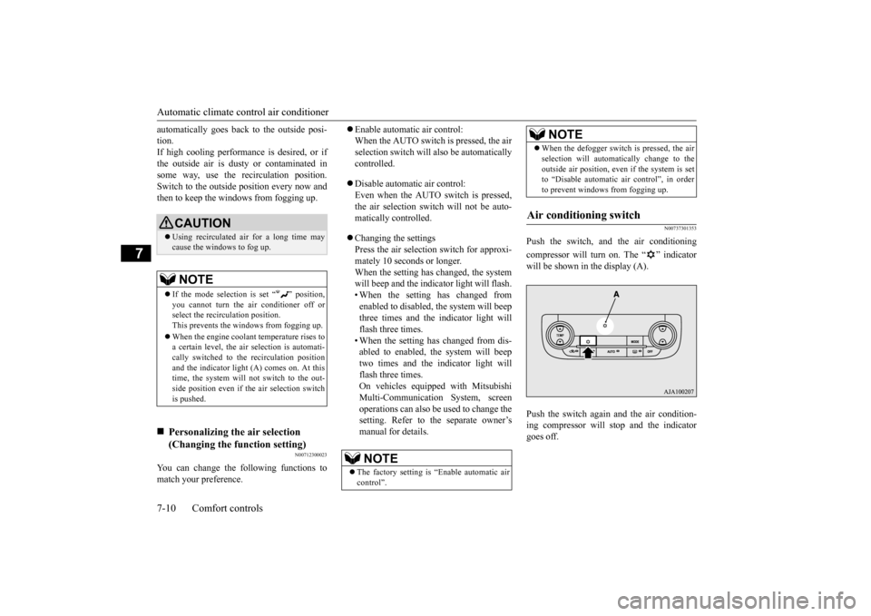
Push the switch, and the air conditioning compressor will turn on. The “ ” indicator will be shown in the display (A). Push the switch again and the air condition- ing compressor will stop and the indicatorgoes off.
CAUTION Using recirculated air for a long time may cause the windows to fog up.NOTE
If the mode selection
is set “ ” position,
you cannot turn the ai
r conditioner off or
select the recirc
ulation position.
This prevents the windows from fogging up. When the engine coolan
t temperature rises to
a certain level, the air selection is automati- cally switched to the
recirculation position
and the indicator light
(A) comes on. At this
time, the system will not switch to the out- side position even if
the air selection switch
is pushed.
Personalizing the air selection (Changing the function setting)
NOTE
The factory setting is
“Enable automatic air
control”.
When the defogger switch is pressed, the air selection will automati
cally change to the
outside air position, even if the system is setto “Disable automatic air control”, in order to prevent windows from fogging up.
Air conditioning switch
NOTE
BK0211800US.book 10 ページ 2014年3月12日 水曜日 午後2時42分