2015 MITSUBISHI OUTLANDER ECO mode
[x] Cancel search: ECO modePage 359 of 446
System Settings 7-44 Comfort controls
7
Set the time manually. 1. Select “YES” at the “Adjust time” screen, and press the /SEL key. The hour can be adjusted. Press the
/SEL key again to adjust the minutes.
2. Turn the /SEL key to adjust the time.3. Press the /SEL key. This completes the adjustment.
Change the mobile phone voice cut- in set- tings and the Bluetooth
® 2.0 interface lan-
guage.
Depending on the vehi
cle, PHONE settings
may not be possible.
Supported profiles A hands-free kit (available separately) is required. (“Set value” bold typefa
ce indicates factory
default settings.)
*2:Once the CODE (passcode) of your
choice is entered, each time th
e /SET key is pressed, this swit
ches in the order Settings chan
nel select,
Change LOCK settings, a
nd Complete settings.
To return to “each channel LOCK setting”, press the
6 key. Input the CODE from the 1 RPT key to the 6 key.
Time Setting
NOTE
In order to finish ad
justing the time, hold
down the /SEL key unt
il the seconds are
reset to “00”.
PHONE Settings
NOTE
Cancel functions such as the mobile phone “dial lock”, and connect while on thestandby screen. While connected, mobile phone (receiving calls, etc.) operations
may not function cor-
rectly. Depending on the distance between the prod- uct and the mobile
phone, the conditions
within the vehicle, and types of screening,connection may not be
possible. In these
cases, situate the mobile phone as close as possible to the product. Even though a Bluet
ooth-capable mobile
phone, characteristics a
nd specifications may
mean that correct ope
ration may not be pos-
sible. For safety’s sake, do
not operate the mobile
phone while driving.
When operating the
mobile phone, first stop the vehicle in a safelocation. Even though a Bluet
ooth-capable mobile
phone, phone specifications
and settings may
result in differences in display, or prevent correct operation.
Some models may not
be confirmed as con-
nected, or may not connect.Hands-free
HFP(v1.5)
Phonebook transfer
OPP(v1.1), PBAP(v1.0)
Vehicles without a Bluetooth
® 2.0 Inter-
faceSettings value
Settings content
PHONE OFF
Do not use mobile phone voice cut-in.
PHONE MUTE
During mobile phone voice cut- in, mute the audio.
PHONE AT T
During mobile phone voice cut- in, output audio from all speak- ers.
NOTE
BK0211800US.book 44 ページ 2014年3月12日 水曜日 午後2時42分
Page 368 of 446
Jump-starting the engine For emergencies 8-3
8
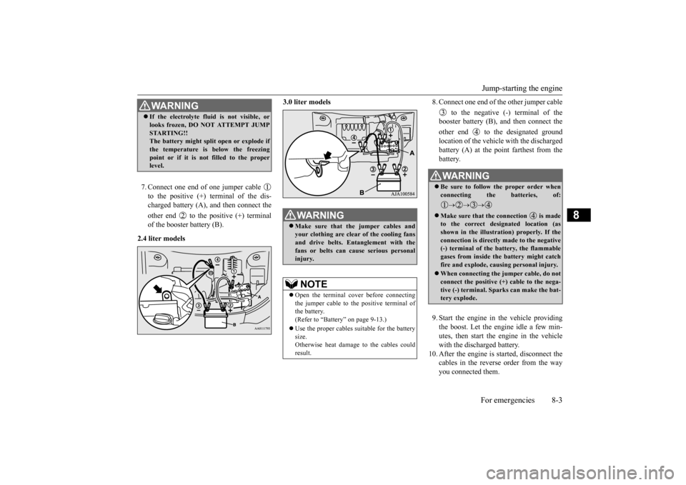
7. Connect one end of one jumper cable to the positive (+) terminal of the dis- charged battery (A),
and then connect the
other end to the positive (+) terminal of the booster battery (B).
2.4 liter models
3.0 liter models
8. Connect one end of the other jumper cable
to the negative (-) terminal of the booster battery (B), a
nd then connect the
other end to the designated ground location of the vehicl
e with the discharged
battery (A) at the point farthest from the battery. 9. Start the engine in the vehicle providing the boost. Let the engine idle a few min- utes, then start the engine in the vehiclewith the discharged battery.
10. After the engine is
started, disconnect the
cables in the reverse order from the wayyou connected them.
WA R N I N G If the electrolyte flui
d is not visible, or
looks frozen, DO NOT ATTEMPT JUMPSTARTING!!The battery might split open or explode if the temperature is below the freezing point or if it is not filled to the properlevel.
WA R N I N G Make sure that the jumper cables and your clothing are clear of the cooling fans and drive belts. Entanglement with thefans or belts can ca
use serious personal
injury.NOTE
Open the terminal cover before connecting the jumper cable to the positive terminal of the battery.(Refer to “Battery” on page 9-13.) Use the proper cables suitable for the battery size. Otherwise heat damage
to the cables could
result.
WA R N I N G Be sure to follow the proper order when connecting the batteries, of:
Make sure that the connection is made to the correct designated location (as shown in the illustration) properly. If theconnection is directly made to the negative (-) terminal of the battery, the flammable gases from inside the battery might catchfire and explode, caus
ing personal injury.
When connecting the jumper cable, do not connect the positive (+) cable to the nega- tive (-) terminal. Sparks can make the bat- tery explode.
BK0211800US.book 3 ページ 2014年3月12日 水曜日 午後2時42分
Page 380 of 446
Operation under adverse driving conditions
For emergencies 8-15
8
Release the parking brake. Set the selector lever to the “N” (NEUTRAL) position.
N00837201760
If your vehicle becomes
stuck in snow, sand,
or mud, it can often be moved by a rocking motion. Rock your vehicle back and forth to free it.Do not rev the engine or spin the wheels. Constant efforts to free a stuck vehicle can cause overheating and tr
ansaxle failure. Let
the engine idle for a few minutes to cool the transaxle before trying again. If your vehicle is still
stuck after several rock-
ing attempts, call for a commercial tow truck service.
[For front-wheel driv
e vehicle equipped with
the active stability control (ASC)]If the vehicle is towed with the ignitionswitch in the “ON” pos
ition or the operation
mode in ON and only the front wheels raised off the ground (Type C), the ASC may oper-ate, resulting in an accident. When towing the vehicle with the front wheels raised, keep the ignition switch or
the operation mode as
follows. [Except for vehicles equipped with the F. A . S . T. - k e y ]The ignition switch is in “LOCK”, “OFF” or “ACC” position. [Vehicles equipped with the F.A.S.T.-key]The operation mode is in OFF or ACC.
Towing a front-wheel drive vehi- cle with front wheels off the ground (Type C)
CAUTION
Operation under adverse driving conditions If your vehicle becomes stuck in sand, mud or snow
WA R N I N G When trying to rock
your vehicle out of a
stuck position, make sure that there are nopeople nearby. The
rocking motion can
make your vehicle suddenly lurch forward or backward, and inju
re any bystanders.
On wet roads
CAUTIONAvoid flooded roads. Water is often deeper than it looks, and you could be seriously hurtby driving into flood water. When driving in rain, on water-covered roads, or through a car
wash, water could get
into the brake discs and make them fail tem- porarily. In such cases, lightly press thebrake pedal to see if they are working prop- erly. If they are not, press the pedal lightly several times while driving to dry the brakepads or linings, then check them again. When driving in rain, a layer of water may form between the tires and the road surface (hydroplaning). This loosens your tires’ grip on the road, making it difficult to steer orbrake properly. When driving on a wet road:• Drive your vehicle at a safe speed.• Do not drive on worn tires.• Always keep the tires at the correct infla- tion pressures.
BK0211800US.book 15 ページ 2014年3月12日 水曜日 午後2時42分
Page 387 of 446
Engine oil and oil filter 9-6 Vehicle care and maintenance
9
N00937702024
It is normal for an engi
ne to use oil. You may
need to add oil between the recommended oil change intervals. Befo
re starting the engine,
check the engine oil leve
l. Refill if necessary.
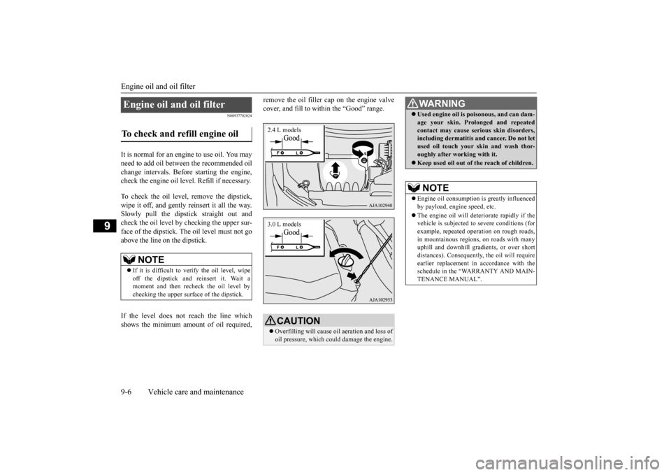
To check the oil level,
remove the dipstick,
wipe it off, and gently reinsert it all the way.Slowly pull the dipsti
ck straight out and
check the oil level by checking the upper sur- face of the dipstick. The oil level must not goabove the line on the dipstick. If the level does not reach the line which shows the minimum am
ount of oil required,
remove the oil filler cap on the engine valve cover, and fill to within the “Good” range.
Engine oil and oil filter To check and refill engine oil
NOTE
If it is difficult to verify the oil level, wipe off the dipstick and
reinsert it. Wait a
moment and then recheck the oil level by checking the upper surface of the dipstick.
CAUTION Overfilling will cause
oil aeration and loss of
oil pressure, which coul
d damage the engine.
2.4 L models3.0 L models
WA R N I N GUsed engine oil is po
isonous, and can dam-
age your skin. Prolonged and repeatedcontact may cause serious skin disorders,including dermatitis and cancer. Do not let used oil touch your sk
in and wash thor-
oughly after working with it. Keep used oil out of
the reach of children.
NOTE
Engine oil consumption
is greatly influenced
by payload, engine speed, etc. The engine oil wi
ll deteriorate rapidly if the
vehicle is subjected to
severe conditions (for
example, repeated operation on rough roads, in mountainous regions, on roads with many uphill and downhill grad
ients, or over short
distances). Consequently
, the oil will require
earlier replacement in accordance with the schedule in the “WARRANTY AND MAIN-TENANCE MANUAL”.
BK0211800US.book 6 ページ 2014年3月12日 水曜日 午後2時42分
Page 391 of 446
Automatic transaxle fl
uid (if so equipped)
9-10 Vehicle care and maintenance
9
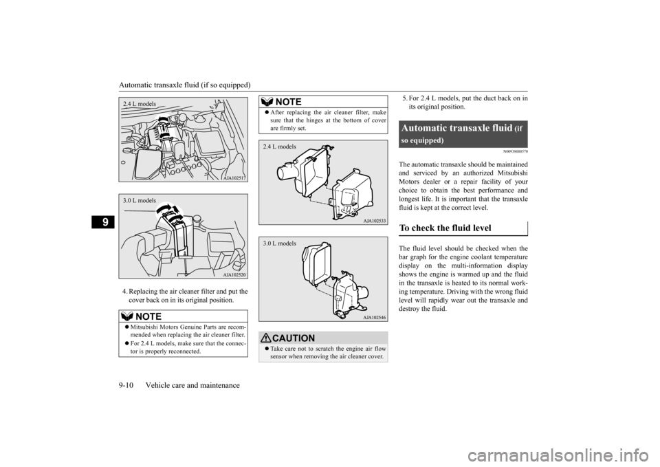
4. Replacing the air clea
ner filter and put the
cover back on in its original position.
5. For 2.4 L models, put the duct back on in its original position.
N00938000570
The automatic transaxle should be maintainedand serviced by an au
thorized Mitsubishi
Motors dealer or a repair facility of your choice to obtain the best performance and longest life. It is impor
tant that the transaxle
fluid is kept at the correct level. The fluid level should be checked when the bar graph for the engine coolant temperaturedisplay on the multi-information display shows the engine is wa
rmed up and the fluid
in the transaxle is heated to its normal work-ing temperature. Driving with the wrong fluid level will rapidly wear
out the transaxle and
destroy the fluid.
NOTE
Mitsubishi Motors Genui
ne Parts are recom-
mended when replacing th
e air cleaner filter.
For 2.4 L models, make sure that the connec- tor is properl
y reconnected.
2.4 L models3.0 L models
After replacing the air cleaner filter, make sure that the hinges at the bottom of coverare firmly set.CAUTION Take care not to scratc
h the engine air flow
sensor when removing
the air cleaner cover.
NOTE
2.4 L models3.0 L models
Automatic transaxle fluid
(if
so equipped)To check the fluid level
BK0211800US.book 10 ページ 2014年3月12日 水曜日 午後2時42分
Page 393 of 446
Rear axle oil (All-wheel drive models) 9-12 Vehicle care and maintenance
9
N00915201279
Whenever the oil level is checked, add oil as necessary to maintain the proper level. Fill with the oil according to the table below.
N00938601313
The windshield and rear
window washer fluid
reservoir is in the engine compartment.
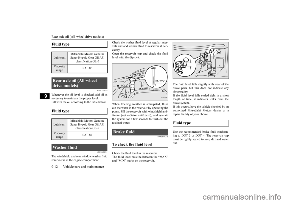
Check the washer fluid
level at regular inter-
vals and add washer fluid to reservoir if nec-essary. Open the reservoir cap and check the fluid level with the dipstick. When freezing weather is anticipated, flush out the water in the reservoir by operating thepump. Fill the reservoir with windshield anti- freeze (not radiator
antifreeze), and operate
the system for a few se
conds to flush out the
residual water.
N00938701271
Check the fluid level in the reservoir.The fluid level must be between the “MAX” and “MIN” marks on the reservoir.
The fluid level falls slightly with wear of the brake pads, but this
does not indicate any
abnormality. If the fluid level falls se
aled tight in a short
length of time, it indi
cates leaks from the
brake system. If this occurs, have the vehicle checked by an authorized Mitsubishi Motors dealer or arepair facility of your choice. Use the recommended brake fluid conform- ing to DOT 3 or DOT
4. The reservoir cap
must be tightly sealed to keep dirt and water out.
Fluid type Lubricant
Mitsubishi Motors Genuine Super Hypoid Gear Oil API
classification GL-5
Viscosity range
SAE 80
Rear axle oil (All-wheel drive models) Fluid type Lubricant
Mitsubishi Motors Genuine Super Hypoid Gear Oil API
classification GL-5
Viscosity range
SAE 80
Washer fluid
Brake fluid To check the fluid level
EMPTY
FULL
Fluid type
BK0211800US.book 12 ページ 2014年3月12日 水曜日 午後2時42分
Page 396 of 446
Tires
Vehicle care and maintenance 9-15
9
Recommended inflation pressure: the inflation pressure for optimum tire perfor-mance. Intended outboard sidewall: • The sidewall that c
ontains a whitewall,
bears white letteri
ng or bears manufac-
turer, brand, and/or model name molding that is higher or deeper than the samemolding on the other sidewall of the tire, or • The outward facing si
dewall of an asym-
metrical tire that has a particular side that must always face outward whenmounted on a vehicle.
Passenger car tire: a
tire intended for use
on passenger cars, multipurpose passen-ger vehicles, and trucks that have a gross vehicle weight rati
ng (GVWR) of 10,000
pounds or less. Light truck (LT) tire: a tire designated by its manufacturer as primarily intended for use on lightweight truc
ks or multipurpose
passenger vehicles. Tread: portion of a tire that comes into contact with the road. Tread rib: a tread se
ction running circum-
ferentially around a tire. Tread separation: pulling away of the tread from the tire carcass. Carcass: the tire structure, except tread and sidewall rubber which, when inflated,bears the load.
Sidewall: portion of a tire between the tread and bead. Section width: the line
ar distance between
the exteriors of the sidewalls of an inflated tire, excluding elevations due tolabeling, decoration, or protective bands. Bead: the part of the tire that is made of steel wires, wrapped
or reinforced by ply
cords and that is shaped to fit the rim. Ply: a layer of rubber-coated parallel cords. Cord: the strands forming the plies in the tire. Rim: a metal support for a tire or a tire and tube assembly upon which the tire beads are seated. Rim diameter: nominal diameter of the bead seat. Groove: the space between two adjacent tread ribs.
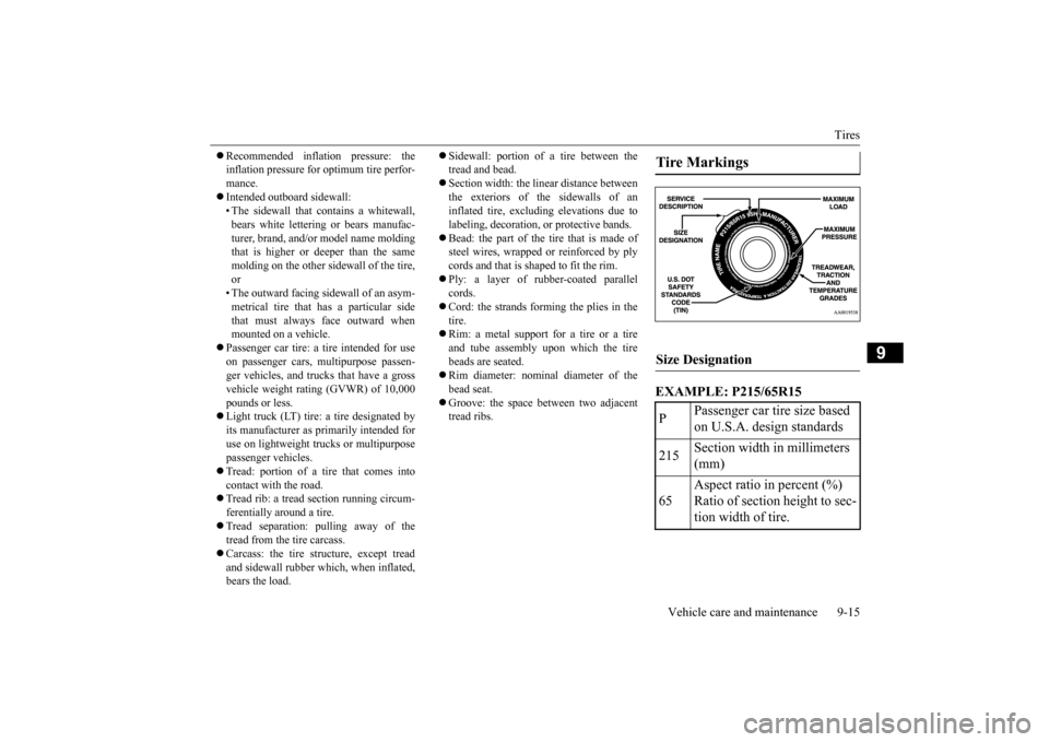
EXAMPLE: P215/65R15Tire Markings Size Designation P
Passenger car tire size based on U.S.A. design standards
215
Section width in millimeters (mm)
65
Aspect ratio in percent (%) Ratio of section height to sec- tion width of tire.
BK0211800US.book 15 ページ 2014年3月12日 水曜日 午後2時42分
Page 409 of 446
Fuses 9-28 Vehicle care and maintenance
9
*: Fusible link Some fuses may not be installed on your vehicle, depending on the vehicle model or specifications. The table above shows the main equip- ment corresponding to each fuse.
The fuse block does not contain spare 7.5 A, 25 A or 30 A fuses. If one of these fusesburns out, substitute w
ith the following fuse.
7.5 A: 10 A spare fuse 25 A: 20 A spare fuse30 A: 30 A audio system amplifier fuse When using a substitute
fuse, replace with a
fuse of the correct capa
city as soon as possi-
ble.
N00954901141
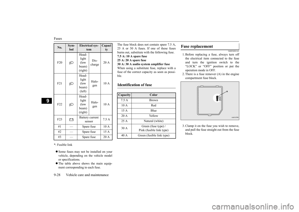
1. Before replacing a fuse, always turn off the electrical item
connected to the fuse
and turn the ignition switch to the“LOCK” or “OFF” position or put the operation mode in OFF. 2. There is a fuse remover (A) in the enginecompartment fuse block. 3. Clamp it on the fuse you wish to remove, and pull the fuse straight out from the fuseblock.
F20
Head- light (low beam) (right)
Dis- charge
20 A
F21
Head- light (low beam) (left)
Halo- gen
10 A
F22
Head- light (low beam) (right)
Halo- gen
10 A
F23
Battery current
sensor
7.5 A
#1 — Spare fuse 10 A #2 — Spare fuse 15 A #3 — Spare fuse 20 ANo.
Sym- bol
Electrical sys-
tem
Capacity
Identification of fuse Capacity
Color
7.5 A Brown 10 A Red 15 A Blue 20 A Yellow 25 A Natural (white) 30 A
Green (fuse type) / Pink (fusible link type)
40 A Green (fusible link type)
Fuse replacement
BK0211800US.book 28 ページ 2014年3月12日 水曜日 午後2時42分