2015 MITSUBISHI LANCER EVOLUTION cooling
[x] Cancel search: coolingPage 116 of 338

Turbocharger operation
Features and controls 5-55
5
N00537300077
The turbocharger increases engine power by pushing large amounts of air into the engine’s cylinders. The finned parts inside the turbo-charger turn at extremely high speeds and are subjected to extremely high temperatures. They are lubricated by engine oil and cooledby engine oil and coolan
t. If the engine oil is
not replaced at the specified intervals, the bearings may seize or emit abnormal noise.
NOTE
For vehicles with Twin Clutch SST, the engine will stop and the vehicle power will turn off approximately 1 second after the ignition switch is turned to the “LOCK” position. The reason for this is that, in the time from when the ignition switch is turned to the“LOCK” position until the engine stops, the gears inside the Twin Clutch SST disengage so that the engine will start smoothly thenext time it is started. Two clutches installed in the Twin Clutch SST alternately engage and disengage toachieve smooth shifting. In addition, the gear on the side with the free clutch is engaged, therefore, quick shifting isperformed. If the engine was stopped with the gear engaged like this, it would provide resistancethe next time the engine is started. Therefore, the gear disengages in the approximately 1- second period until the engine stops. For vehicles with Twin Clutch SST, do not operate the gearshift lever or the acceleratorpedal for approximately 1 second until the engine stops.
If the temperature inside the engine compart- ment is high, the cooling fans (A) will con- tinue to operate for some time even if the engine is stopped. Therefore, the operation sound of the coolingfans may be heard even after the engine is stopped. This sound is normal and does not indicate a malfunction.After operating for a period of time, the cool- ing fans will stop automatically.
Turbocharger operation
CAUTION Do not run the engine at high speeds (for example, by revving it or by accelerating rapidly) immediately after starting it.NOTE
Do not stop the engine immediately after high-speed or uphill driv
ing. First allow the
engine to idle to give the turbocharger a chance to cool down. Engine oil must be properly maintained to avoid engine and/or turbocharger damage. To better protect your engine and turbo-charger, use fully synthetic engine oil.
Turbocharger
CAUTION
BK0210800US.bo
ok 55 ページ 2014年4月8日 火曜日 午前11時28分
Page 241 of 338
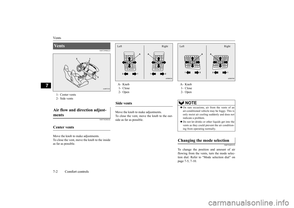
Vents 7-2 Comfort controls
7
N00729900223 N00730200242
Move the knob to make adjustments. To close the vent, move the knob to the inside as far as possible.
Move the knob to make adjustments. To close the vent, move the knob to the out-side as far as possible.
N00736401618
To change the position and amount of airflowing from the vents, turn the mode selec- tion dial. Refer to “Mode selection dial” on page 7-5, 7-10.
Ve n t s 1- Center vents 2- Side ventsAir flow and direction adjust- ments Center vents
A- Knob 1- Close 2- OpenSide vents Left Right
A- Knob 1- Close 2- Open
NOTE
On rare occasions, air from the vents of an air-conditioned vehicle may be foggy. This isonly moist air cooling suddenly and does not indicate a problem. Do not let drinks or ot
her liquids get into the
vents as they could prevent the air condition- ing from operating normally.
Changing the mode selection Left Right
BK0210800US.bo
ok 2 ページ 2014年4月8日 火曜日 午前11時28分
Page 244 of 338

Automatic air conditioning with
Fahrenheit scale (if so equipped)
Comfort controls 7-5
7
N00737001363
Use this dial to adjust the temperature in the passenger compartment. Turn the temperaturecontrol dial clockwise to make the air warmer. Turn it counterclockwise to make the air cooler.
The above indicates the factory settings. You can personalize the air selection switch and air conditioning switch to match your per-sonal preferences. Contact your Mitsubishi Motors dealer or a repair facility of your choice for assistance.Refer to “Personalizing the air conditioning switch (Changing the function setting)” on page 7-7.Refer to “Personalizing the air selection (Changing the function setting)” on page 7-6.
N00737100093
To change the amount of air flowing from the vents, turn the mode selection dial. Refer to“Changing the mode selection” on page 7-2.
N00737200238
Normally, use the outside air position to keepthe windshield and side windows clear and toquickly remove fog or frost from the wind- shield. To change the air selection, simply press the air selection switch. A sound will be madeevery time you press the switch. Outside air {Indicator light (A) OFF} Outside air is introduced into the passen- ger compartment.
Temperature control dial
NOTE
While the engine coolant temperature is low, the temperature of the air from the heater will be cool/cold until the engine warms up, even if you have selected warm air with the dial. When the temperature is set to the highest or the lowest setting under the AUTO opera-tion, the air selection and the air conditioning will be automatically changed as follows. • Quick Heating (When the temperature is set to the highest setting) Outside air will be introduced and the airconditioning will stop. In this case, manual operation is possible. • Quick Cooling (When the temperature is set to the lowest setting) Inside air will be recirculated and the airconditioning will operate. In this case, you cannot select outside air and turn the air conditioning off.
Mode selection dial
Air selection switch
BK0210800US.bo
ok 5 ページ 2014年4月8日 火曜日 午前11時28分
Page 245 of 338
Automatic air conditioning with
Fahrenheit scale (if so equipped)
7-6 Comfort controls
7
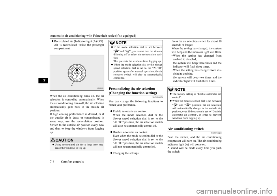
Recirculated air {Indicator light (A) ON} Air is recirculated inside the passenger compartment.
When the air conditioning turns on, the air selection is controlled automatically. When the air conditioning turns off, the air selection automatically goes back to the outside airposition.If high cooling performance is desired, or if the outside air is dusty or contaminated in some way, use the recirculation position.Switch to the outside air position every now and then to keep th
e windows from fogging
up.
N00760000034
You can change the following functions to match your preference. Enable automatic air control: When the mode selection dial or theblower speed selection dial is set to the “AUTO” position, the air selection switch will also be automatically controlled. Disable automatic air control: Even when the mode selection dial or theblower speed selection dial is set to the “AUTO” position, the air selection switch will not be automatically controlled. Changing the settings:
Press the air selection switch for about 10 seconds or longer. When the setting has changed, the system will beep and the indicator light will flash.• When the setting has changed from enabled to disabled, the system will beep three times and theindicator will flash three times. • When the setting has changed from dis- abled to enabled,the system will beep two times and theindicator light will flash three times.
N00737300200
Push the switch, and the air conditioningcompressor will turn on. The air conditioningindicator light (A) will come on. A sound will be made every time you push the switch.
CAUTION Using recirculated air for a long time may cause the windows to fog up.
NOTE
If the mode selection dial is set between “ ” and “ ”, you cannot turn the air con- ditioning off or select the recirculation posi- tion.This prevents the windows from fogging up. When the mode selection dial or the blower speed selection dial is set to the “AUTO” position again after manual operation, the air selection switch will also be automaticallycontrolled.
Personalizing the air selection (Changing the function setting)
NOTE
The factory setting is “Enable automatic air control”. While the mode selection dial is set between “ ” and “ ” position, the air selection will automatically change to the outside air position, even if the sy
stem is set to “Disable
automatic air control”, in order to preventwindows from fogging up.
Air conditioning switch
BK0210800US.bo
ok 6 ページ 2014年4月8日 火曜日 午前11時28分
Page 249 of 338

Automatic air conditioning with
Celsius scale (if so equipped)
7-10 Comfort controls
7
the “OFF” position, all fan-driven airflow will stop.
N00737000236
Use this dial to adjust the temperature in thepassenger compartment. Turn the temperaturecontrol dial clockwise to make the air warmer. Turn it counterclockwise to make the air cooler.
The above indicates the factory settings. You can personalize the air selection switch and air conditioning switch to match your per- sonal preferences.Contact your Mitsubishi Motors dealer or a repair facility of your choice for assistance. Refer to “Personalizing the air conditioningswitch (Changing the function setting)” on page 7-12. Refer to “Personalizing the air selection(Changing the function setting)” on page7-11.
N00737100136
To change the amount of air flowing from thevents, turn the mode selection dial. Refer to “Changing the mode selection” on page 7-2.
Temperature control dial
NOTE
While the engine coolant temperature is low, the temperature of the air from the heater will be cool/cold until the engine warms up,even if you have selected warm air with the dial. When the temperature is set to the highest or the lowest setting under the AUTO opera- tion, the air selection and the air conditioningwill be automatically changed as follows. Also, if the air selection is operated manually after an automatic changeover, manual oper-ation will be selected. • Quick Heating (When the temperature is set to the highest setting) Outside air will be introduced and the air conditioning will stop. • Quick Cooling (When the temperature is set to the lowest setting)Inside air will be recirculated and the air conditioning will operate.
Mode selection dial
BK0210800US.bo
ok 10 ページ 2014年4月8日 火曜日 午前11時28分
Page 250 of 338
Automatic air conditioning with
Celsius scale (if so equipped)
Comfort controls 7-11
7
N00737200241
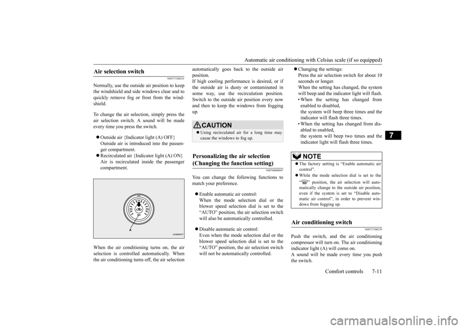
Normally, use the outside air position to keep the windshield and side windows clear and toquickly remove fog or frost from the wind- shield. To change the air selection, simply press the air selection switch. A sound will be madeevery time you press the switch. Outside air {Indicator light (A) OFF} Outside air is introduced into the passen- ger compartment. Recirculated air {Indicator light (A) ON} Air is recirculated inside the passenger compartment.
When the air conditioning turns on, the air selection is controll
ed automatically. When
the air conditioning turns off, the air selection
automatically goes back to the outside air position. If high cooling performance is desired, or if the outside air is dusty or contaminated insome way, use the recirculation position. Switch to the outside air position every now and then to keep th
e windows from fogging
up.
N00760000047
You can change the following functions tomatch your preference. Enable automatic air control: When the mode selection dial or the blower speed selection dial is set to the“AUTO” position, the air selection switch will also be automatically controlled. Disable automatic air control: Even when the mode selection dial or theblower speed selection dial is set to the “AUTO” position, the air selection switch will not be automatically controlled.
Changing the settings: Press the air selection switch for about 10 seconds or longer. When the setting has changed, the systemwill beep and the indicator light will flash. • When the setting has changed from enabled to disabled,the system will beep three times and the indicator will flash three times. • When the setting has changed from dis-abled to enabled,the system will beep two times and the indicator light will flash three times.
N00737300239
Push the switch, and the air conditioning compressor will turn on. The air conditioning indicator light (A) will come on. A sound will be made every time you pushthe switch.
Air selection switch
CAUTION Using recirculated air for a long time may cause the windows to fog up.
Personalizing the air selection (Changing the function setting)
NOTE
The factory setting is “Enable automatic air control”. While the mode selection dial is set to the “ ” position, the air selection will auto- matically change to the outside air position,even if the system is set to “Disable auto- matic air control”, in order to prevent win- dows from fogging up.
Air conditioning switch
BK0210800US.bo
ok 11 ページ 2014年4月8日 火曜日 午前11時28分
Page 253 of 338
Important air conditioning operating tips 7-14 Comfort controls
7
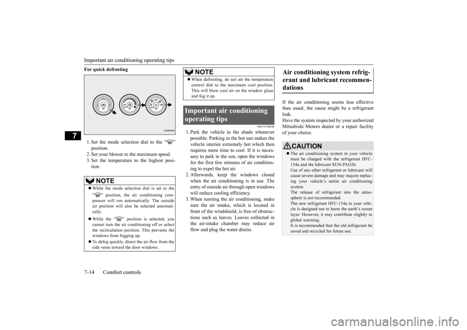
For quick defrosting 1. Set the mode selection dial to the “ ” position. 2. Set your blower to the maximum speed. 3. Set the temperature to the highest posi-tion.
N00733700280
1. Park the vehicle in the shade wheneverpossible. Parking in the hot sun makes the vehicle interior extremely hot which then requires more time to cool. If it is neces-sary to park in the sun, open the windows for the first few minutes of air condition- ing to expel the hot air.2. Afterwards, keep the windows closed when the air conditioning is in use. The entry of outside air through open windowswill reduce cooling efficiency. 3. When running the air conditioning, make sure the air intake, which is located infront of the windshield, is free of obstruc- tions such as leaves. Leaves collected in the air-intake chamber may reduce airflow and plug the water drains.
If the air conditioning seems less effective than usual, the cause might be a refrigerant leak.Have the system inspected by your authorized Mitsubishi Motors dealer or a repair facility of your choice.
NOTE
While the mode selection dial is set to the “ ” position, the air conditioning com- pressor will run automatically. The outside air position will also be selected automati-cally. While the “ ” position is selected, you cannot turn the air conditioning off or select the recirculation position. This prevents thewindows from fogging up. To defog quickly, direct
the air flow from the
side vents toward the door windows.
When defrosting, do not set the temperature control dial to the maximum cool position. This will blow cool air on the window glass and fog it up.
Important air conditioning operating tips
NOTE
Air conditioning system refrig- erant and lubricant recommen- dations
CAUTION The air conditioning system in your vehicle must be charged with the refrigerant HFC-134a and the lubricant SUN-PAG56. Use of any other refrigerant or lubricant will cause severe damage and may require replac-ing your vehicle’s entire air conditioning system. The release of refrigerant into the atmo-sphere is not recommended. The new refrigerant HFC-134a in your vehi- cle is designed not to harm the earth’s ozonelayer. However, it may contribute slightly to global warming. It is recommended that the old refrigerant be saved and recycled for future use.
BK0210800US.bo
ok 14 ページ 2014年4月8日 火曜日 午前11時28分
Page 260 of 338
Jump-starting the engine For emergencies 8-3
8
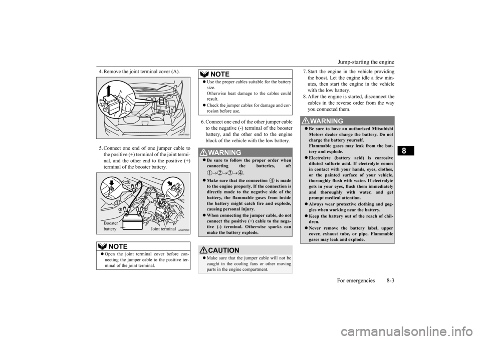
4. Remove the joint terminal cover (A). 5. Connect one end of one jumper cable to the positive (+) terminal of the joint termi-nal, and the other end to the positive (+) terminal of the booster battery.
6. Connect one end of the other jumper cable to the negative (-) terminal of the boosterbattery, and the other end to the engineblock of the vehicle with the low battery.
7. Start the engine in the vehicle providing the boost. Let the engine idle a few min- utes, then start the engine in the vehicle with the low battery.8. After the engine is started, disconnect the cables in the reverse order from the way you connected them.
NOTE
Open the joint terminal cover before con- necting the jumper cable to the positive ter- minal of the joint terminal. Booster battery
Joint terminal
Use the proper cables suitable for the battery size. Otherwise heat damage to the cables could result. Check the jumper cables for damage and cor- rosion before use.WA R N I N G Be sure to follow the proper order when connecting the batteries, of:
.
Make sure that the connection is made to the engine properly. If the connection isdirectly made to the negative side of the battery, the flammable gases from inside the battery might catch fire and explode,causing personal injury. When connecting the jumper cable, do not connect the positive (+) cable to the nega- tive (-) terminal. Otherwise sparks can make the battery explode.CAUTION Make sure that the jumper cable will not be caught in the cooling fans or other movingparts in the engine compartment.NOTE
WA R N I N G Be sure to have an authorized Mitsubishi Motors dealer charge the battery. Do not charge the battery yourself. Flammable gases may leak from the bat-tery and explode. Electrolyte (battery acid) is corrosive diluted sulfuric acid. If electrolyte comes in contact with your hands, eyes, clothes, or the painted surface of your vehicle,thoroughly flush with water. If electrolyte gets in your eyes, flush them immediately and thoroughly with water, and getprompt medical attention. Always wear protective clothing and gog- gles when working near the battery. Keep the battery out of the reach of chil- dren. Never remove the battery label, upper cover, exhaust tube, or pipe. Flammable gases may leak and explode.
BK0210800US.bo
ok 3 ページ 2014年4月8日 火曜日 午前11時28分