2015 MINI COUPE ROADSTER CONVERTIBLE ABS
[x] Cancel search: ABSPage 38 of 231
moves to a stable position. The sequence can
be continued using the switch.
The opening or closing procedure is also inter‐
rupted when it is blocked mechanically. To be
able to reactivate the convertible top in this
case:1.Switch the ignition off and on again.2.Press the switch to continue the sequence
in the desired direction.
Opening and closing procedure
Do not interrupt the closing procedure
Do not interrupt and resume the closing
procedure several times in close succession as
this could damage the convertible top mecha‐
nism. ◀
If, after having been activated a number of
times in close succession, the convertible top
can only be moved in one direction, the
convertible top system is overheated. Let the
system cool for approx. 4 minutes.
If the battery was disconnected, for example to
change the battery or to put the vehicle into
storage, reinitialize, refer to page 33, the power
windows; otherwise, the windows will not be
lowered, and it will not be possible to open the
convertible top.
Convenient opening and closing Convenient operation is possible via the remote
control, refer to page 22, and the door lock, re‐
fer to page 25.
Manual closing in case of electrical
malfunction
Only close the convertible top manually if
there is an electrical malfunction
Only close the convertible top manually if this is
absolutely necessary; never open it manually.
Damage may occur if incorrectly operated. The
closing procedure must be fully completed;
otherwise, there is a risk of injury or damage. ◀
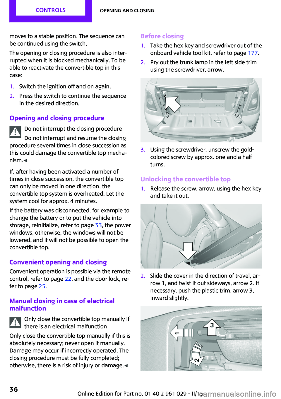
Before closing1.Take the hex key and screwdriver out of the
onboard vehicle tool kit, refer to page 177.2.Pry out the trunk lamp in the left side trim
using the screwdriver, arrow.3.Using the screwdriver, unscrew the gold-
colored screw by approx. one and a half
turns.
Unlocking the convertible top
1.Release the screw, arrow, using the hex key
and take it out.2.Slide the cover in the direction of travel, ar‐
row 1, and twist it out sideways, arrow 2. If
necessary, push the plastic trim, arrow 3,
inward slightly.Seite 36CONTROLSOpening and closing36
Online Edition for Part no. 01 40 2 961 029 - II/15
Page 44 of 231

able to reactivate the convertible top in this
case:1.Switch the ignition off and on again.2.Press the switch to continue the sequence
in the desired direction.
Opening and closing the convertible top
Switch on the radio ready state or the ignition, refer to page 56.
If possible, conserve the battery by only operat‐
ing the convertible top while the engine is run‐
ning.
Before closing the convertible top, remove all
foreign objects from the windshield frame that
could prevent the top from closing properly.
Opening
1.Fold out the handle and turn it all the way
to the end, arrow.2.Push the unlocked convertible top upward
at the handle and open it about a hand's
width.3.Press the switch back to open the
convertible top. The windows opens during
this procedure.
Closing
1.Press the switch forward.2.Pull the convertible top onto the windshield
frame.3.Turn the handle clockwise until it engages
audibly.
The convertible top is locked.
If the convertible top was open for a
lengthy period, it may be necessary to ap‐
ply greater force when locking the top.4.Fold the handle back in.5.Close the windows if necessary.
Manual closing in case of electrical
malfunction
Only close the convertible top manually if
there is an electrical malfunction
Only close the convertible top manually if this is
absolutely necessary; never open it manually.
Damage may occur if incorrectly operated. The
closing procedure must be fully completed;
otherwise, there is a risk of injury or damage. ◀
Before closing
Lower the side windows slightly, switch off the
engine, and switch off the ignition.
1.Take out the cover plate, refer to
page 107.Seite 42CONTROLSOpening and closing42
Online Edition for Part no. 01 40 2 961 029 - II/15
Page 93 of 231
Driving stability control systemsVehicle equipment
This chapter describes all series equipment as
well as country-specific and special equipment
offered for this model series. Therefore, it also
describes equipment that may not be found in
your vehicle, for instance due to the selected
special equipment or the country version. This
also applies to safety-related functions and sys‐
tems.
When using the features and systems described
here, adhere to local regulations.
Antilock Brake System
ABS
ABS prevents locking of the wheels during braking.
Steerability is maintained even during full brak‐
ing. This increases active driving safety.
ABS is operational every time you start the en‐
gine.
Electronic brake-force distribution EBVThe system controls the brake pressure in the
rear wheels to ensure stable braking behavior.
CBC Cornering Brake Control
When braking in curves or during a lane
change, driving stability and steering response
are improved further.
Brake assistant When the brakes are applied rapidly, this sys‐
tem automatically produces the maximum
braking force boost. In this way, the system
helps keep the braking distance as short aspossible. This system utilizes all of the benefits
provided by ABS.
Do not reduce the pressure on the brake pedal
for the duration of full braking.
Dynamic Stability Con‐ trol DSC
The concept
DSC prevents traction loss in the driving wheels
when driving away and accelerating.
DSC also recognizes unstable vehicle condi‐
tions, such as fishtailing or nose-diving. Subject
to physical limits, DSC helps to keep the vehicle
on a steady course by reducing engine speed
and by applying brakes to the individual
wheels.
DSC is operational every time you start the en‐
gine.
Adjust your driving style to the situation
An appropriate driving style is always the
responsibility of the driver.
The laws of physics cannot be repealed, even
with DSC.
Do not reduce the additional safety margin
with a risky driving style, as otherwise there is a
risk of an accident. ◀
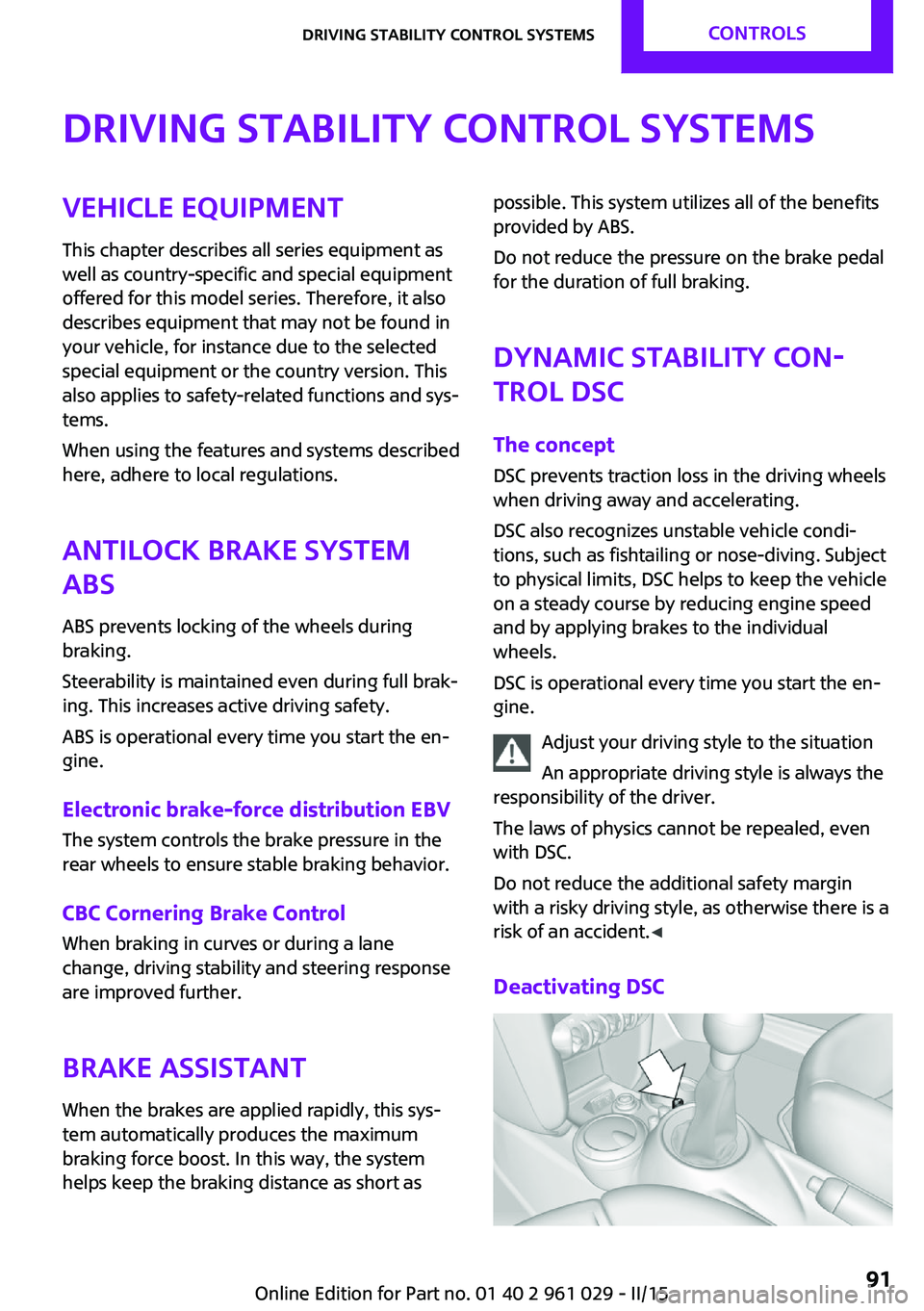
Deactivating DSCSeite 91Driving stability control systemsCONTROLS91
Online Edition for Part no. 01 40 2 961 029 - II/15
Page 118 of 231

Braking safelyThe vehicle is equipped with ABS as a standardfeature.
Applying the brakes fully is the most effective
way of braking in situations when this is neces‐
sary.
The vehicle maintains steering responsiveness.
You can still avoid any obstacles with a mini‐
mum of steering effort.
Pulsation of the brake pedal and sounds from
the hydraulic circuits indicate that ABS is in its
active mode.
Do not let your foot rest on the brake
pedal
Do not drive with your foot resting on the brake
pedal. Even light but consistent pedal pressure
can lead to high temperatures, brake wear and
possibly even brake failure. ◀
Objects in the area around the pedals No objects in the area around the pedals
Keep floor mats, carpets, and any other
objects out of the area of motion of the pedals;
otherwise, the function of the pedals could be
impeded while driving
Do not place additional floor mats over existing
mats or other objects.
Only use floor mats that have been approved
for the vehicle and can be properly fixed in
place.
Ensure that the floor mats are securely fastened
again when they are returned after being re‐
moved, such as for cleaning. ◀
Driving in wet conditions When roads are wet or there is heavy rain,
briefly exert gentle pressure on the brake pedal
every few miles.
Ensure that this action does not endanger other
road users.The heat generated in this process helps dry
the brake discs and pads.
In this way braking efficiency will be available
when you need it.
HillsDrive long or steep downhill gradients in the
gear in which the least braking is required. Oth‐
erwise, the brake system may overheat, result‐
ing in a reduction in the brake system effi‐
ciency.
You can increase the engine's braking effect by
shifting down, going all the way to first gear, if
necessary.
Downshifting in manual mode of the Steptronic
transmission, refer to page 64.
Avoid load on the brakes
Avoid placing excessive load on the brake
system. Light but consistent brake pressure can
lead to high temperatures, brake wear and
possibly even brake failure. ◀
Do not drive in neutral
Never drive with the transmission in neu‐
tral, with the engine switched off or with the
clutch depressed; otherwise, you will have nei‐
ther the braking action of the engine or nor its
power assistance when braking or steering. ◀
Brake disc corrosion
Corrosion on the brake discs and contamina‐
tion on the brake pads are furthered by:▷Low mileage.▷Extended periods when the vehicle is not
used at all.▷Infrequent use of the brakes.
Corrosion occurs when the minimum pressure
that must be exerted by the pads during brake
applications to clean the discs is not reached.
Should corrosion form on the brake discs, the
brakes will tend to respond with a pulsating ef‐
fect that generally cannot be corrected.
Seite 116DRIVING TIPSThings to remember when driving116
Online Edition for Part no. 01 40 2 961 029 - II/15
Page 167 of 231
DOT … 0315: the tire was manufactured in the
3rd week of 2015.
Changing wheels and
tires
Mounting Information on mounting tires
Have mounting and balancing performed
only by a service center or tire specialist.
If this work is not carried out properly, there is
the danger of subsequent damage and related
safety hazards. ◀
Wheel and tire combination
Information on the right wheel and tire combi‐
nation and rim version for your vehicle can be
obtained from the service center.
Incorrect wheel and tire combinations impair
the function of a variety of systems such as ABS
or DSC.
To maintain good handling and vehicle re‐
sponse, use only tires with a single tread con‐
figuration from a single manufacturer.
Following tire damage, have the original wheel
and tire combination remounted on the vehicle
as soon as possible.
Approved wheels and tires
The manufacturer of your vehicle recom‐
mends that you use only wheels and tires that
have been approved for your particular vehicle
model.
For example, despite having the same official
size ratings, variations can lead to body contact
and with it, the risk of severe accidents.
The manufacturer of your vehicle cannot evalu‐
ate non-approved wheels and tires to deter‐
mine if they are suited for use, and therefore
cannot ensure the operating safety of the vehi‐
cle if they are mounted. ◀Wheels with electronics for TPM Tire
Pressure Monitor
When mounting new tires or changing from
summer to winter tires or vice versa, only use
wheels with TPM electronics; otherwise, the
Tire Pressure Monitor will not be able to detect
a flat tire, refer to page 86. Your service center
will be glad to advise you.
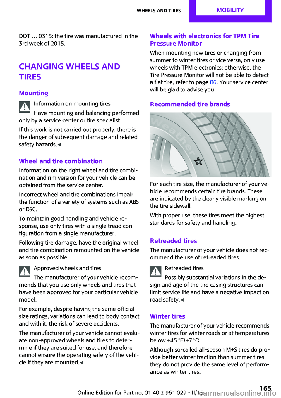
Recommended tire brands
For each tire size, the manufacturer of your ve‐
hicle recommends certain tire brands. These
are indicated by the clearly visible marking on
the tire sidewall.
With proper use, these tires meet the highest
standards for safety and handling.
Retreaded tires
The manufacturer of your vehicle does not rec‐
ommend the use of retreaded tires.
Retreaded tires
Possibly substantial variations in the de‐
sign and age of the tire casing structures can
limit service life and have a negative impact on
road safety. ◀
Winter tires The manufacturer of your vehicle recommends
winter tires for winter roads or at temperatures
below +45 ℉/+7 ℃.
Although so-called all-season M+S tires do pro‐
vide better winter traction than summer tires,
they do not provide the same level of perform‐
ance as winter tires.
Seite 165Wheels and tiresMOBILITY165
Online Edition for Part no. 01 40 2 961 029 - II/15
Page 184 of 231
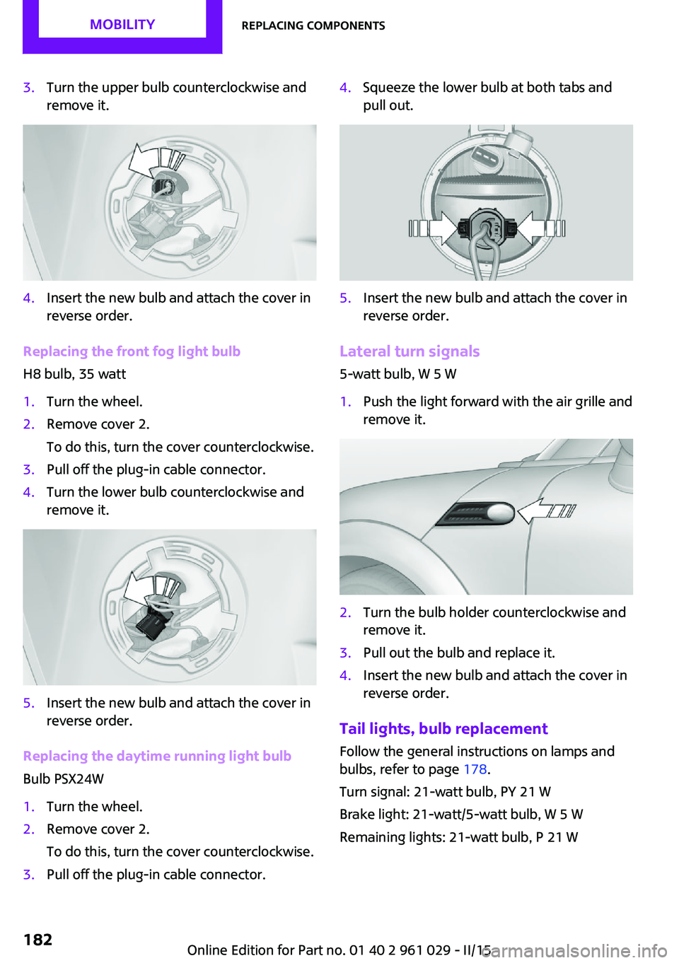
3.Turn the upper bulb counterclockwise and
remove it.4.Insert the new bulb and attach the cover in
reverse order.
Replacing the front fog light bulb
H8 bulb, 35 watt
1.Turn the wheel.2.Remove cover 2.
To do this, turn the cover counterclockwise.3.Pull off the plug-in cable connector.4.Turn the lower bulb counterclockwise and
remove it.5.Insert the new bulb and attach the cover in
reverse order.
Replacing the daytime running light bulb
Bulb PSX24W
1.Turn the wheel.2.Remove cover 2.
To do this, turn the cover counterclockwise.3.Pull off the plug-in cable connector.4.Squeeze the lower bulb at both tabs and
pull out.5.Insert the new bulb and attach the cover in
reverse order.
Lateral turn signals
5-watt bulb, W 5 W
1.Push the light forward with the air grille and
remove it.2.Turn the bulb holder counterclockwise and
remove it.3.Pull out the bulb and replace it.4.Insert the new bulb and attach the cover in
reverse order.
Tail lights, bulb replacement
Follow the general instructions on lamps and
bulbs, refer to page 178.
Turn signal: 21-watt bulb, PY 21 W
Brake light: 21-watt/5-watt bulb, W 5 W
Remaining lights: 21-watt bulb, P 21 W
Seite 182MOBILITYReplacing components182
Online Edition for Part no. 01 40 2 961 029 - II/15
Page 192 of 231

Do not touch live parts
To avoid the risk of potentially fatal injury,
always avoid all contact with electrical compo‐
nents while the engine is running. ◀
Preparation1.Check whether the battery of the other ve‐
hicle has a voltage of 12 volts and approxi‐
mately the same capacitance in Ah. This in‐
formation can be found on the battery.2.Switch off the engine of the assisting vehi‐
cle.3.Switch off any electronic systems/power
consumers in both vehicles.
Bodywork contact between vehicles
There must not be any contact between
the bodies of the two vehicles, otherwise there
is a danger of shorting. ◀
Connecting jumper cables
Connecting order
Connect the jumper cables in the correct
order; otherwise, there is the danger of injury
from sparking. ◀1.Open the battery cover in the engine com‐
partment to access the positive terminal.2.Unlock the tabs of the positive terminal
cover on the left and right, arrows 1, and
raise the cover, arrow 2.3.Attach one terminal clamp of the positive
jumper cable to the positive terminal of the
battery or to a starting aid terminal of the
vehicle providing assistance.4.Attach the second clamp of the positive
jumper cable to the positive terminal of the
battery of the vehicle to be started.5.Attach one terminal clamp of the negative
jumper cable to the negative terminal of
the battery, or to the corresponding engine
or body ground of the vehicle providing as‐
sistance.6.Attach the second clamp of the negative
jumper cable to the negative terminal ofSeite 190MOBILITYBreakdown assistance190
Online Edition for Part no. 01 40 2 961 029 - II/15
Page 208 of 231
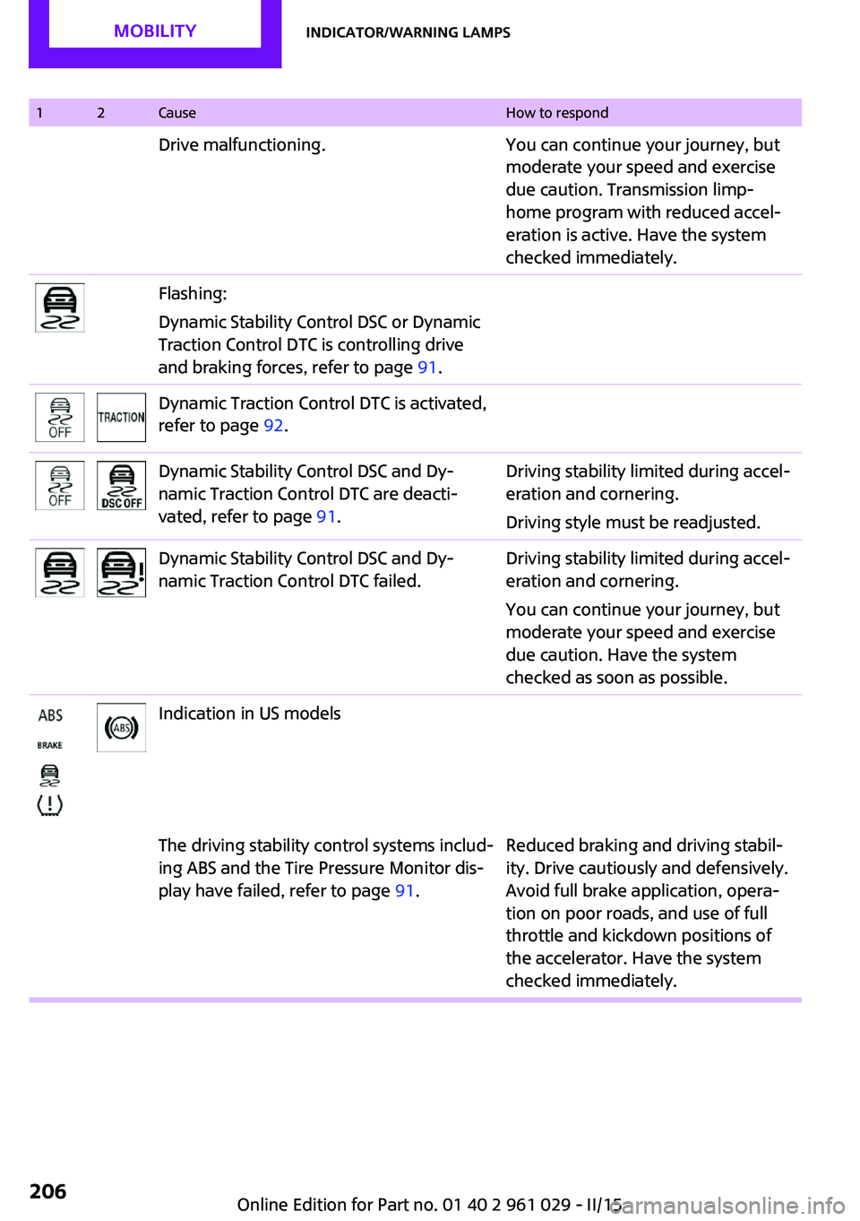
12CauseHow to respondDrive malfunctioning.You can continue your journey, but
moderate your speed and exercise
due caution. Transmission limp-
home program with reduced accel‐
eration is active. Have the system
checked immediately.Flashing:
Dynamic Stability Control DSC or Dynamic
Traction Control DTC is controlling drive
and braking forces, refer to page 91.Dynamic Traction Control DTC is activated,
refer to page 92.Dynamic Stability Control DSC and Dy‐
namic Traction Control DTC are deacti‐
vated, refer to page 91.Driving stability limited during accel‐
eration and cornering.
Driving style must be readjusted.Dynamic Stability Control DSC and Dy‐
namic Traction Control DTC failed.Driving stability limited during accel‐
eration and cornering.
You can continue your journey, but
moderate your speed and exercise
due caution. Have the system
checked as soon as possible.Indication in US modelsThe driving stability control systems includ‐
ing ABS and the Tire Pressure Monitor dis‐
play have failed, refer to page 91.Reduced braking and driving stabil‐
ity. Drive cautiously and defensively.
Avoid full brake application, opera‐
tion on poor roads, and use of full
throttle and kickdown positions of
the accelerator. Have the system
checked immediately.Seite 206MOBILITYIndicator/warning lamps206
Online Edition for Part no. 01 40 2 961 029 - II/15