2015 MINI COUPE ROADSTER CONVERTIBLE towing
[x] Cancel search: towingPage 40 of 231

Ensure that the locking pieces do not fall
onto the vehicle, as this could cause dam‐
age.4.Insert the pins into the respective mount on
the cowl, arrow.
Locking the convertible top
Turn the hex key opposite to the direction of
arrow 2 until the convertible top is locked.
Please contact your service center to eliminate
the malfunction.
MINI Convertible: wind
deflector
The wind deflector keeps air movements in the
passenger compartment to a minimum when
the convertible top is open and provides an
even more comfortable ride, even at high
speeds.
Do not allow pointed object to come into con‐
tact with the wind deflector as these may dam‐
age the net. Do not place any objects on the in‐
stalled wind deflector. When stowing, make
sure that the wind deflector is not damaged by
objects.
Before installing
1.Take the wind deflector out of the pouch.2.Unfold the wind deflector, see arrows.3.Push together the catches until they en‐
gage, see arrows.
Mounting and unfolding
1.Push out retaining pin 2 on one side until it
engages.2.Insert the retaining pins of the wind deflec‐
tor into the provided openings 1 and 2 on
this side of the vehicle.3.Push back retaining pin 1 against the spring
force on the other side of the vehicle and
insert it in the provided opening.Seite 38CONTROLSOpening and closing38
Online Edition for Part no. 01 40 2 961 029 - II/15
Page 67 of 231

Manually unlocking the selector lever
lock
If the selector lever is locked in position P al‐
though the ignition is switched on, the brake is
depressed, and the button on the selector lever
is pressed, the selector lever lock can be over‐
ridden:1.Switch off the ignition.2.Unclip the sleeve of the selector lever.3.Pull the sleeve up over the selector lever
until the sleeve is inside out.
Pull off the plug-in cable connector if nec‐
essary.4.Insert the pulling hook 1 from the onboard
vehicle tool kit into the loop on the passen‐
ger side.5.Pull the loop upward.6.Move the selector lever into the desired po‐
sition, pressing the button on the front of
the selector lever.
Set the parking brake
Manually unlock the selector lever lock
for towing only. Before manually unlocking the
selector lever lock, pull the parking brake
firmly; otherwise, the vehicle may roll away and
cause personal injury or property damage. ◀
Seite 65DrivingCONTROLS65
Online Edition for Part no. 01 40 2 961 029 - II/15
Page 121 of 231

available cargo and luggage load capacity
calculated in Step 4.6.If your vehicle will be towing a trailer, load
from your trailer will be transfered to your
vehicle. Consult the manual for transporting
a trailer to determine how this may reduce
the available cargo and luggage load ca‐
pacity of your vehicle.
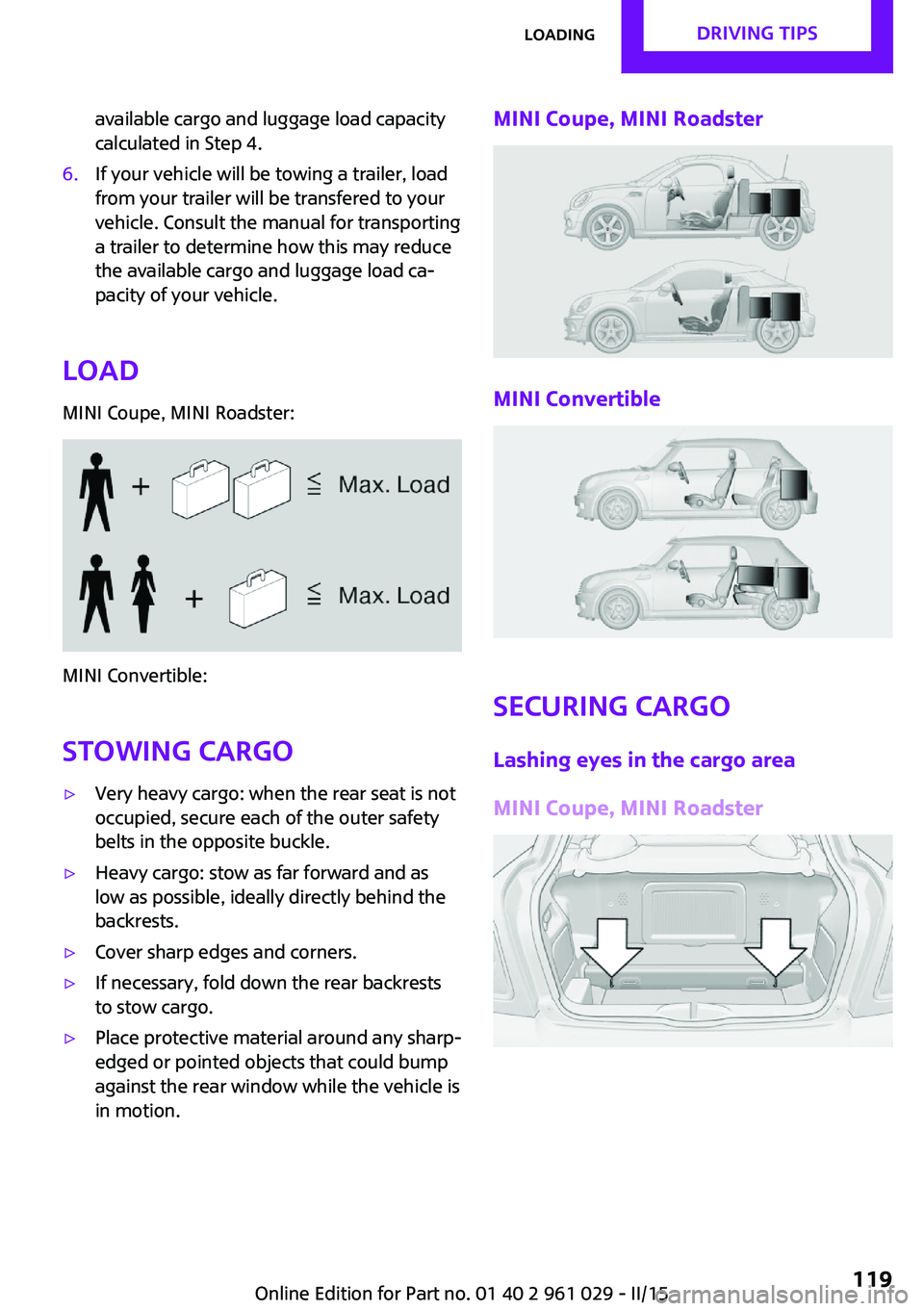
Load
MINI Coupe, MINI Roadster:
MINI Convertible:
Stowing cargo
▷Very heavy cargo: when the rear seat is not
occupied, secure each of the outer safety
belts in the opposite buckle.▷Heavy cargo: stow as far forward and as
low as possible, ideally directly behind the
backrests.▷Cover sharp edges and corners.▷If necessary, fold down the rear backrests
to stow cargo.▷Place protective material around any sharp-
edged or pointed objects that could bump
against the rear window while the vehicle is
in motion.MINI Coupe, MINI Roadster
MINI Convertible
Securing cargo
Lashing eyes in the cargo area
MINI Coupe, MINI Roadster
Seite 119LoadingDRIVING TIPS119
Online Edition for Part no. 01 40 2 961 029 - II/15
Page 170 of 231

3.Insert the sealant bottle into the compres‐
sor housing in a vertical position.4.Unscrew the dust cap off of the valve of the
defective wheel and screw the filling hose 2
of the sealant bottle onto the valve.5.Ensure that the compressor is switched off.6.Insert connector 5 into the lighter socket/
socket in the passenger compartment, refer
to page 106.7.When the engine is running:
Switch on the compressor and let it run for
approx. 3 to 8 minutes to fill sealant into
the tire and achieve a tire inflation pressure
of approx. 1.8 bar/26 psi.
While sealant is being filled, the inflation
pressure may intermittently rise to approx.
5 bar/73 psi. Do not switch off the com‐
pressor in this phase.8.Switch off the compressor.
Do not allow the compressor to run too
long
Do not allow the compressor to run longer than
10 minutes; otherwise, the device will overheat
and may be damaged. ◀
If an air pressure of 1.8 bar/26 psi is not
reached:
1.Unscrew the filling hose 2 from the wheel
and drive forward and back approx.
33 ft/10 m to evenly distribute the sealant
in the tire.2.Inflate the tire again using the compressor.If the inflation pressure of 1.8 bar/26 psi is still
not reached, the tire is too heavily damaged.
Contact the nearest service center.
Stowing the Mobility System1.Unscrew the filling hose 2 of the sealant
bottle from the wheel.2.Unscrew the compressor connection hose 6
from the sealant bottle.3.Connect the filling hose 2 of the sealant
bottle with the free connector on the seal‐
ant bottle.
This prevents left-over sealant from escap‐
ing from the bottle.4.Wrap the empty sealant bottle in suitable
material to avoid dirtying the cargo area.5.Stow the Mobility System back in the vehi‐
cle.
Distributing the sealant
Drive approx. 3.1 miles/5 km to evenly distrib‐
ute the sealant.
Do not exceed a speed of 50 mph/80 km/h. If
possible, do not drop below a speed of
10 mph/20 km/h.
Correcting the tire inflation pressure
1.After driving approx. 3.1 miles/5 km, or
about 10 minutes, stop in a suitable loca‐
tion.2.Screw the connection hose 6 of the com‐
pressor directly onto the tire valve.3.Insert the connector 5 into the power
socket in the passenger compartment.4.Correct the tire inflation pressure to
1.8 bar/26 psi. When the engine is running:▷To increase the inflation pressure:
switch on the compressor. To check the
currently set inflation pressure, switch
off the compressor.▷To reduce the inflation pressure: press
the release button 9.Seite 168MOBILITYWheels and tires168
Online Edition for Part no. 01 40 2 961 029 - II/15
Page 193 of 231

the battery, or to the engine or body
ground of the vehicle to be started.
Body ground:
Starting the engine
Never use spray fluids to start the engine.
1.Start the engine of the assisting vehicle and
let it run for several minutes at a slightly in‐
creased idle speed.2.Start the engine of the vehicle being started
in the usual way.
If the first starting attempt is not successful,
wait a few minutes before making another
attempt in order to allow the discharged
battery to recharge.3.Let both engines run for several minutes.4.Disconnect the jumper cables in the reverse
order.
Check the battery and recharge if necessary.
Tow-starting and towing
Notes Observe applicable laws and regulations
Observe applicable laws and regulations
for tow-starting and towing. ◀
No additional passengers
Do not transport any passengers other
than the driver in a vehicle that is being
towed. ◀
Using a tow fitting
The screw-in tow fitting must always be carried
in the vehicle. It can be screwed in at the front
or rear of the MINI.
Tow fitting, information on use▷Use only the tow fitting provided with
the vehicle and screw it all the way in.▷Use the tow fitting for towing on paved
roads only.▷Avoid lateral loading of the tow fitting, e.g.,
do not lift the vehicle by the tow fitting.
Otherwise, damage to the tow fitting and the
vehicle can occur. ◀
Access to the screw thread Push out the tow fitting cover at the appropri‐
ate recess in the bumper.
Front
Rear
John Cooper Works with aerodynamic bumper:
Pull out the tow fitting cover in the bumper in
the lower section, arrow.
Seite 191Breakdown assistanceMOBILITY191
Online Edition for Part no. 01 40 2 961 029 - II/15
Page 194 of 231

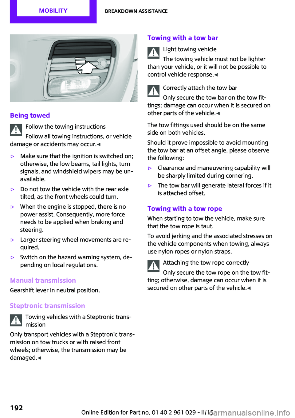
Being towedFollow the towing instructions
Follow all towing instructions, or vehicle
damage or accidents may occur. ◀
▷Make sure that the ignition is switched on;
otherwise, the low beams, tail lights, turn
signals, and windshield wipers may be un‐
available.▷Do not tow the vehicle with the rear axle
tilted, as the front wheels could turn.▷When the engine is stopped, there is no
power assist. Consequently, more force
needs to be applied when braking and
steering.▷Larger steering wheel movements are re‐
quired.▷Switch on the hazard warning system, de‐
pending on local regulations.
Manual transmission
Gearshift lever in neutral position.
Steptronic transmission Towing vehicles with a Steptronic trans‐
mission
Only transport vehicles with a Steptronic trans‐
mission on tow trucks or with raised front
wheels; otherwise, the transmission may be
damaged. ◀
Towing with a tow bar
Light towing vehicle
The towing vehicle must not be lighter
than your vehicle, or it will not be possible to
control vehicle response. ◀
Correctly attach the tow bar
Only secure the tow bar on the tow fit‐
tings; damage can occur when it is secured on
other parts of the vehicle. ◀
The tow fittings used should be on the same
side on both vehicles.
Should it prove impossible to avoid mounting
the tow bar at an offset angle, please observe
the following:▷Clearance and maneuvering capability will
be sharply limited during cornering.▷The tow bar will generate lateral forces if it
is attached offset.
Towing with a tow rope
When starting to tow the vehicle, make sure
that the tow rope is taut.
To avoid jerking and the associated stresses on
the vehicle components when towing, always
use nylon ropes or nylon straps.
Attaching the tow rope correctly
Only secure the tow rope on the tow fit‐
ting; otherwise, damage can occur when it is
secured on other parts of the vehicle. ◀
Seite 192MOBILITYBreakdown assistance192
Online Edition for Part no. 01 40 2 961 029 - II/15
Page 195 of 231

Towing with a tow truck
Have the MINI transported with a tow truck
with a so-called lift bar or on a flat bed.
Do not lift the vehicle
Do not lift the vehicle by the tow fitting or
body and chassis parts; otherwise, damage
may result. ◀
Tow-starting
If possible, start the engine by jump-starting,
refer to page 189, it rather than tow-starting
the vehicle. Vehicles with a catalytic converter
should only be tow-started when the engine is
cold; vehicles with an automatic transmission
cannot be tow-started.
1.Switch on the hazard warning system and
comply with local regulations.2.Switch on the ignition, refer to page 56.3.Engage third gear.4.Have the vehicle tow-started with the
clutch is depressed and then slowly release
the clutch. After the engine starts, immedi‐
ately depress the clutch completely again.5.Stop at a suitable location, remove the tow
bar or rope, and switch off the hazard
warning system.6.Have the vehicle checked.Seite 193Breakdown assistanceMOBILITY193
Online Edition for Part no. 01 40 2 961 029 - II/15
Page 228 of 231

Temperature display, externaltemperature 66
Temperature display, setting the units 70
Temperature warning 66
Theft alarm system, refer to Alarm system 31
Tilt alarm sensor 32
Time, setting the time 71
Tire age 164
Tire, flat tire 85
Tire identification marks 162
Tire inflation pressure 156
Tire inflation pressure, pres‐ sure loss, FTM 85
Tire pressure loss, RDC 87
Tire, pressure monitoring, re‐ fer to Tire Pressure Monitor
TPM 86
Tire pressure monitor, refer to Flat Tire Monitor 84
Tire Pressure Monitor TPM 86
Tire Pressure Monitor TPM, system limits 89
Tire Pressure Monitor TPM, system reset 87
Tire Pressure Monitor TPM, warning lamp 87
Tire Quality Grading 163
Tires, breaking in 114
Tires, changing 165
Tires, condition 163
Tires, damage 164
Tire size 162
Tires, minimum tread 164
Tires, retreaded tires 165
Tires, storage 166
Tire tread 163
Tool kit, refer to Onboard ve‐ hicle tool kit 177
Tools, refer to Onboard vehi‐ cle tool kit 177
Towing another vehicle 191
Towing, being towed 191
Tow-starting 191 TPM, refer to Tire Pressure
Monitor 86
Traction control 92
Transmission lock, refer to Changing the selector lever
positions 63
Transmission, overriding the selector lever lock with Step‐
tronic transmission 65
Transmission, refer to Manual transmission 62
Transmission, see Steptronic transmission 63
Transporting children safely 51
Trip-distance counter, refer to Trip odometer 66
Triple turn signal activa‐ tion 59
Trip odometer 66
Trunk lid, emergency opera‐ tion, refer to Unlocking man‐
ually 27
Trunk, opening from the in‐ side 27
Turning lights, refer to Adap‐ tive Light Control 77
Turn signal, bulb replace‐ ment 181
Turn signal indicator lamp 14
Turn signals 59
Turn signals, triple turn signal activation 59
U
Uniform Tire Quality Grading/ UTQG 163
Unintentional alarms, avoid‐ ing 32
Units, average fuel consump‐ tion 70
Units, temperature 70
Unlocking from the inside 26
Unlocking, from the out‐ side 22 Unlocking, tailgate 30
Unlocking, without remote control, refer to Comfort Ac‐
cess 29
Upholstery care 197
Upholstery material care 197
USB audio interface 135
V Vanity mirror 105
Vehicle battery 187
Vehicle, breaking in 114
Vehicle care 195
Vehicle care, refer to Care 194
Vehicle equipment 6
Vehicle paintwork, care 196
Vehicle storage 198
Vehicle, switching off 58
Vehicle wash 194
Ventilation, air condi‐ tioner 104
W Warning and indicator lamps 15
Warning and indicator lamps, overview 199
Warning messages, refer to Check Control 73
Warning triangle 189
Washer/wiper system 60
Washer/wiper system, rain sensor 60
Washer/wiper system, washer fluid 62
Washer fluid 62
Washer fluid reservoir 62
Washing, vehicle 194
Welcome lights 77
Wheel change 184
Wheels and tires 156
Wheels, changing 165 Seite 226REFERENCEEverything from A to Z226
Online Edition for Part no. 01 40 2 961 029 - II/15