Page 272 of 290

the curb weight and the weight of the acces-
sories.
TIN (Tire Identificatio nNumber)
This is auniqu eide ntifier which can be used
by atirem anufacturer to identify tires ,for
exampl efor ap roduct recall, and thu side ntify
the purchasers. Th eTIN is made up of the
manufacturer's identity code, tir esize, tire
typ ecodea nd the manufacturing date.
Load bearin gind ex
Th eloa db eari ng index (als oloa dindex) is a
cod etha tcontains the maximum load bearing
capacity of atire.
Traction
Tractio nist he resul toffrictio nbetween the
tires and the roa dsurface.
Treadwea rind icators
This is indicated by narrow bars (treadwear
bars) tha tare distributed ove rthe tir etread. If
the tir etrea disl evel with the bars, the wear
limi tof 1
/ 16 in (1.
6mm) ha sbeenr eached.
Occupant distribution
Th ed istributio nofoccupants in avehicl eat
their designated seating positions.
Tota lloa dl im it
Rated cargo and luggag eloa dp lus68k ilo-
grams (15 0lb) times the vehicle' sdesig nated
seating capacity. Changin
gawheel Flat tire
Th e" Breakdown assistance" section
(Y page 235 )contains information and notes
on ho wtod ealw ithaf latt ire. Rotatin
gthe wheels G
WARNING
Interchanging the front and rea rwheel smay
severel yimpair the driving characteristics if
the wheels or tires have different dimensions. Th ew heel brakes or suspensio ncomponents
ma yalsobed amaged .The re is ariskofa cci-
dent.
Rotate front and rea rwheel sonlyift he wheels
and tires ar eofthe same dimensions.
! On vehicles equipped with
atirep ressure
monitor, electroni ccomponents are
locate dinthe wheel.
Tire-mounting tools shoul dnot be used
nea rthe valve. This could damage the elec-
troni ccomponents.
Onl yhavet ires change dataqualified spe-
cialist workshop.
Alway spayattentio ntothe instructions and
safety note swhenc hanging awheel
( Y page 271).
Th ew earp atterns on the front and rea rtires
differ, depending on the operating conditions.
Rotate the wheels befor eaclear wear pattern
ha sformed on the tires .Front tires typically
wear mor eonthe shoulders and the rea rtires
in the center.
If your vehicle' stirec onfiguration allows ,you
can change the wheels according to the inter-
vals in the tir emanufacturer's warranty book
in your vehicl edocum ents.Ifnow arranty
book is available, the tires shoul dberotated
every 3,000 to 6,000 mile s(5,000 to
10,000 km), or earlie riftirew earrequires .Do
not change the directio nofwheelrotation.
Clea nthe contact surfaces of the whee land
the brake disc thoroughly every tim eawheel
is rotated .Check the tir epressure and reac-
tivate the tir epressure monitor if necessary. Directio
nofrotation
Tires with aspecified directio nofrotation
have additional benefits, e.g .ifthere is arisk 270
Changin
gawheelWheels an dtires
Page 274 of 290

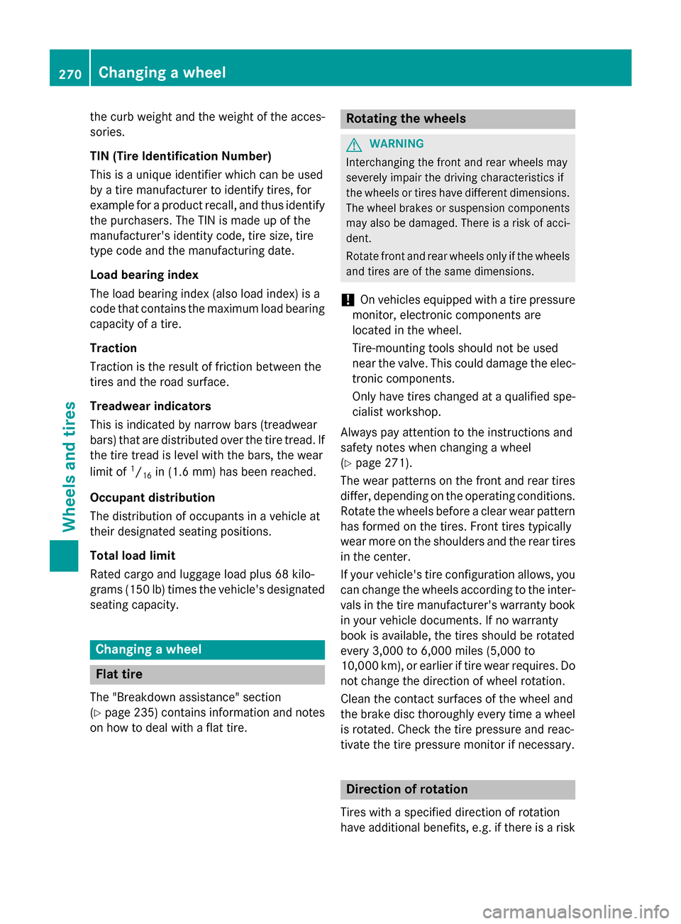
Securing the vehicle on level ground
X On level ground: place chocks or other
suitabl eitem sunder the front and rea rof
the wheel that is diagonall yopposite the
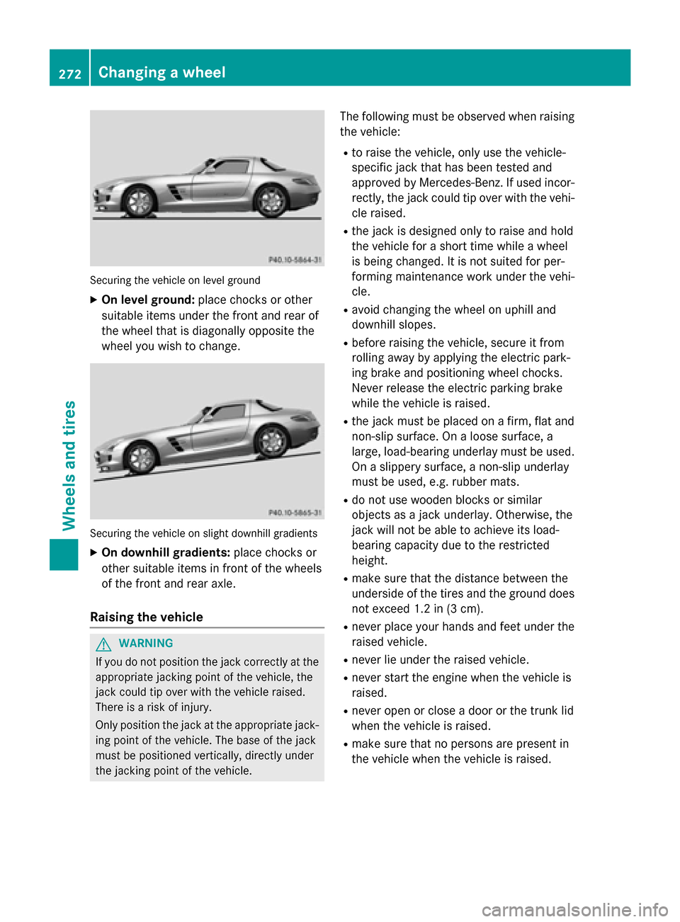
wheel yo uwishtoc hange. Securing the vehicle on slight downhil
lgradients
X On downhill gradients: place chocks or
othe rsuitabl eitem sinf ront of the wheels
of the front and rea raxle.
Raisin gthe vehicle G
WARNING
If yo udon ot position the jack correctly at the
appropriate jacking point of the vehicle ,the
jack could tip ove rwitht he vehicle raised.
There is ariskofi njury.
Only position the jack at the appropriate jack-
ing point of the vehicle .The base of the jack
mus tbep ositioned vertically ,directl yunder
the jacking point of the vehicle. The following mus
tbeo bserve dwhenr aising
the vehicle:
R to raise the vehicle ,only us ethe vehicle-
specifi cjack that ha sbeent ested and
approved by Mercedes-Benz. If used incor-
rectly, the jack could tip ove rwitht he vehi-
cle raised.
R the jack is designe donly to raise and hold
the vehicle for ashort time whil eawheel
is being changed .Itisnot suited for per-
forming maintenance work under the vehi-
cle.
R avoid changing the wheel on uphil land
downhil lslopes.
R before raising the vehicle ,secure it from
rolling away by applying the electri cpark-
ing brake and positioning wheel chocks.
Neve rrelease the electri cparking brake
whil ethe vehicle is raised.
R the jack mus tbep lace donaf irm,flata nd
non-slip surface. On aloose surface, a
large ,load-bearing underlay mus tbeu sed.
On aslippery surface, anon-slip underlay
mus tbeu sed, e.g. rubber mats.
R do not us ewoodenb locks or similar
objects as ajack underlay .Otherwise, the
jack will not be able to achieve its load-
bearing capacity du etothe restricted
height.
R make sure that the distance between the
underside of the tire sand the ground does
not excee d1.2 in (3 cm).
R never place your hands and fee tunder the
raised vehicle.
R never li eunder the raised vehicle.
R never star tthe engine when the vehicle is
raised.
R never ope norclosead oorort he trunk lid
when the vehicle is raised.
R make sure that no persons are present in
the vehicle when the vehicle is raised. 272
Changing
awheelWheels and tires
Page 277 of 290

X
Tighten the wheel bolts until they are fin-
ger-tight.
X Unscrew the alignment bolt.
X Tighten the last wheel bolt until it is finger-
tight.
Lowering the vehicle G
WARNING
The wheels could work loose if the wheel nuts and bolts are not tightened to the specified
tightening torque. There is arisk of accident.
Have the tightening torque immediately
checked at aqualified specialist workshop
after awheel is changed.
X Turn the crank of the jack counter-clock-
wise until the vehicle is once again standing
firmly on the ground.
X Place the jack to one side. X
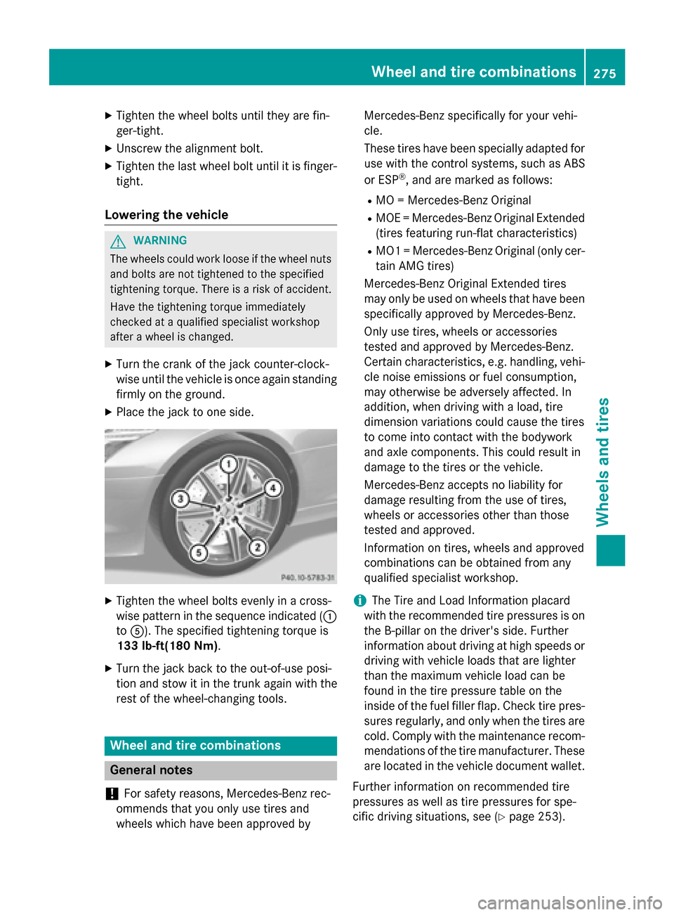
Tighten the wheel bolts evenly in across-
wise pattern in the sequence indicated ( 0043
to 0083). The specified tightening torque is
133 lb-ft(180 Nm).
X Turn the jack back to the out-of-use posi-
tion and stow it in the trunk again with the
rest of the wheel-changin gtools. Wheel and tire combinations
General notes
! For safety reasons, Mercedes-Benz rec-
ommends that you only use tires and
wheels which have been approved by Mercedes-Benz specifically for your vehi-
cle.
These tires have been specially adapted for
use with the control systems, such as ABS
or ESP ®
,a nd are marked as follows:
R MO =Mercedes-Benz Original
R MOE =Mercedes-Benz Original Extended
(tires featuring run-flat characteristics)
R MO1 =Mercedes-Benz Original (only cer-
tain AMG tires)
Mercedes-Benz Original Extended tires
may only be used on wheels that have been
specifically approved by Mercedes-Benz.
Only use tires, wheels or accessories
tested and approved by Mercedes-Benz.
Certain characteristics, e.g. handling, vehi-
cle noise emissions or fuel consumption,
may otherwise be adversely affected. In
addition, when driving with aload, tire
dimension variations could cause the tires
to come into contact with the bodywork
and axle components. This could result in
damage to the tires or the vehicle.
Mercedes-Benz accepts no liability for
damage resulting from the use of tires,
wheels or accessories other than those
tested and approved.
Information on tires, wheels and approved
combinations can be obtained from any
qualified specialist workshop.
i The Tire and Load Information placard
with the recommended tire pressures is on the B-pillar on the driver's side. Further
information about driving at high speeds or driving with vehicle loads that are lighter
than the maximum vehicle load can be
found in the tire pressure table on the
inside of the fuel filler flap. Check tire pres- sures regularly, and only when the tires arecold. Comply with the maintenance recom-
mendation softhe tire manufacturer. These
are located in the vehicle document wallet.
Further information on recommended tire
pressures as well as tire pressures for spe-
cific driving situations, see (Y page 253). Wheel and tirec
ombinations
275Wheels and tires Z
Page:
< prev 1-8 9-16 17-24