2015 MERCEDES-BENZ SLK-Class seats
[x] Cancel search: seatsPage 104 of 358
If somebody becomes trapped:
R press one of the memory function position
buttons, or
R press one of the memory function memory
buttons, or
R move the switch for steering wheel adjust-
ment in the opposite direction to that in
which the steering wheel is moving
The adjustment process is stopped. G
WARNING
If you use openings in the bodywork or
detachable parts as steps, you could:
R slip and/or fall
R damage the vehicle and cause yourself to
fall.
There is a risk of injury.
Always use secure climbing aids, e.g. a suita-
ble ladder.
The EASY-ENTRY/EXIT feature makes getting
in and out of your vehicle easier.
You can activate and deactivate the EASY-
ENTRY/EXIT feature in the on-board com-
puter (Y page 207).
Position of the steering wheel when the EASY-ENTRY/EXIT feature is active The steering wheel swings upwards when
you:
R remove the SmartKey from the ignition lock
R open the driver's door with KEYLESS-GO in
position 1
R open the driver's door and the SmartKey is
in position 0or 1in the ignition lock
i The steering wheel only moves upwards if
it has not already reached the upper end
stop. Position of the steering wheel for driv-
ing The steering wheel is moved to the last selec-
ted position when:
R the driver's door is closed
R you insert the SmartKey into the ignition
lock
or
R you press the Start/Stop button once on
vehicles with KEYLESS-GO
When you close the driver's door with the
ignition switched on, the steering wheel is
also automatically moved to the previously
set position.
The last position of the steering wheel is
stored when you switch off the ignition or
when you store the setting with the memory
function (Y page 106).
Crash-responsive EASY-EXIT feature If the crash-responsive EASY-EXIT feature is
triggered in an accident, the steering column
will move upwards when the driver's door is
opened. This occurs irrespective of the posi-
tion of the SmartKey in the ignition lock. This
makes it easier to exit the vehicle and rescue the occupants.
The crash-responsive EASY-EXIT feature is
only operational if the EASY-EXIT/ENTRY fea-
ture is activated in the on-board computer
(Y page 207). 102
Steering wheelSeats, steering wheel and mirrors
Page 105 of 358
Mirrors
Rear-view mirror
X
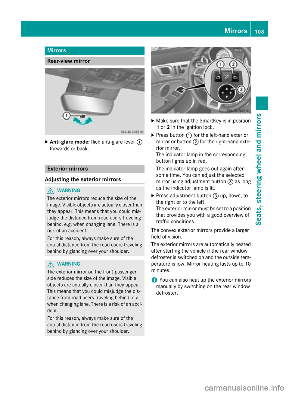
Anti-glare mode: flick anti-glare lever 0043
forwards or back. Exterior mirrors
Adjusting the exterior mirrors G
WARNING
The exterior mirrors reduce the size of the
image. Visible objects are actually closer than they appear. This means that you could mis-
judge the distance from road users traveling
behind, e.g. when changing lane. There is a
risk of an accident.
For this reason, always make sure of the
actual distance from the road users traveling
behind by glancing over your shoulder. G
WARNING
The exterior mirror on the front-passenger
side reduces the size of the image. Visible
objects are actually closer than they appear.
This means that you could misjudge the dis-
tance from road users traveling behind, e.g.
when changing lane. There is a risk of an acci-
dent.
For this reason, always make sure of the
actual distance from the road users traveling
behind by glancing over your shoulder. X
Make sure that the SmartKey is in position
1 or 2in the ignition lock.
X Press button 0043for the left-hand exterior
mirror or button 0044for the right-hand exte-
rior mirror.
The indicator lamp in the corresponding
button lights up in red.
The indicator lamp goes out again after
some time. You can adjust the selected
mirror using adjustment button 0087as long
as the indicator lamp is lit.
X Press adjustment button 0087up, down, to
the right or to the left.
The exterior mirror must be set to a position
that provides you with a good overview of
traffic conditions.
The convex exterior mirrors provide a larger
field of vision.
The exterior mirrors are automatically heated after starting the vehicle if the rear window
defroster is switched on and the outside tem-
perature is low. Mirror heating lasts up to 10 minutes.
i You can also heat up the exterior mirrors
manually by switching on the rear window
defroster. Mirrors
103Seats, steering wheel and mirrors Z
Page 106 of 358

Folding the exterior mirrors in or out
electrically X
Make sure that the SmartKey is in position
1 or 2in the ignition lock.
X Briefly press button 0043.
Both exterior mirrors fold in or out.
i Make sure that the exterior mirrors are
always folded out fully while driving. They
could otherwise vibrate.
Folding the exterior mirrors in or out
automatically If the "Fold in mirrors when locking" function
is activated in the on-board computer
(Y page 208):
R the exterior mirrors fold in automatically as
soon as you lock the vehicle from the out-
side.
R the exterior mirrors fold out again automat-
ically as soon as you unlock the vehicle and
then open the driver's or front-passenger
door.
i The exterior mirrors do not fold out if they
have been folded in manually.
Exterior mirror pushed out of position If an exterior mirror has been pushed out of
position, proceed as follows:
X Vehicles without electrically folding
exterior mirrors: move the exterior mirror
into the correct position manually.
X Vehicles with electrically folding exte-
rior mirrors: press and hold mirror-folding button
0043until you hear a click and then the
mirrors engage in position (Y page 104).
The mirror housing is engaged again and
you can adjust the exterior mirrors as usual
(Y page 103). Automatic anti-glare mirrors
G
WARNING
Electrolyte may escape if the glass in an auto- matic anti-glare mirror breaks. The electrolyte
is harmful and causes irritation. It must not
come into contact with your skin, eyes, res-
piratory organs or clothing or be swallowed.
There is a risk of injury.
If you come into contact with the electrolyte,
observe the following:
R Rinse off the electrolyte from your skin
immediately with water.
R Immediately rinse the electrolyte out of
your eyes thoroughly with clean water.
R If the electrolyte is swallowed, immediately
rinse your mouth out thoroughly. Do not
induce vomiting.
R If electrolyte comes into contact with your
skin or hair or is swallowed, seek medical
attention immediately.
R Immediately change out of clothing which
has come into contact with electrolyte.
R If an allergic reaction occurs, seek medical
attention immediately.
The rear-view mirror and the exterior mirror
on the driver's side automatically go into anti-
glare mode if the following conditions are met simultaneously:
R the ignition is switched on and
R incident light from headlamps strikes the
sensor in the rear-view mirror.
The mirrors do not go into anti-glare mode if
reverse gear is engaged or if the interior light-
ing is switched on. 104
MirrorsSeats, steering wheel and
mirrors
Page 107 of 358
Parking position for the exterior mir-
ror on the front-passenger side
Setting and storing the parking position Using reverse gear
You can position the front-passenger side
exterior mirror in such a way that you can see
the rear wheel on that side as soon as you
engage reverse gear. You can store this posi-
tion.
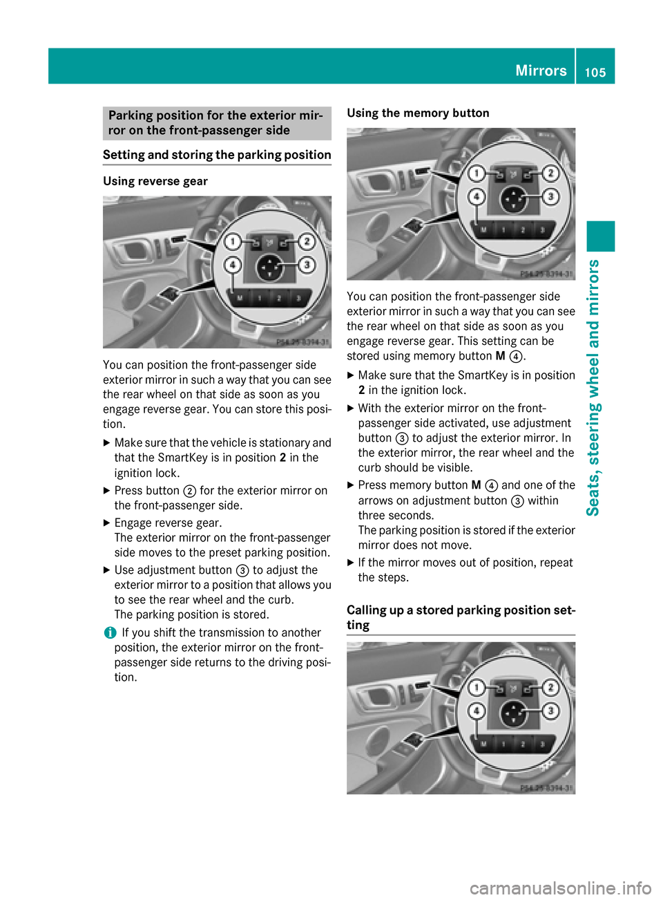
X Make sure that the vehicle is stationary and
that the SmartKey is in position 2in the
ignition lock.
X Press button 0044for the exterior mirror on
the front-passenger side.
X Engage reverse gear.
The exterior mirror on the front-passenger
side moves to the preset parking position.
X Use adjustment button 0087to adjust the
exterior mirror to a position that allows you to see the rear wheel and the curb.
The parking position is stored.
i If you shift the transmission to another
position, the exterior mirror on the front-
passenger side returns to the driving posi-
tion. Using the memory button You can position the front-passenger side
exterior mirror in such a way that you can see
the rear wheel on that side as soon as you
engage reverse gear. This setting can be
stored using memory button M0085.
X Make sure that the SmartKey is in position
2 in the ignition lock.
X With the exterior mirror on the front-
passenger side activated, use adjustment
button 0087to adjust the exterior mirror. In
the exterior mirror, the rear wheel and the
curb should be visible.
X Press memory button M0085 and one of the
arrows on adjustment button 0087within
three seconds.
The parking position is stored if the exterior
mirror does not move.
X If the mirror moves out of position, repeat
the steps.
Calling up a stored parking position set- ting Mirrors
105Seats, steering wheel and mirrors Z
Page 108 of 358
X
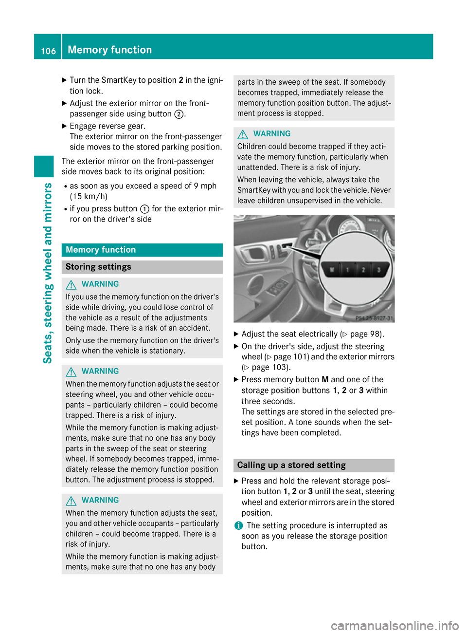
Turn the SmartKey to position 2in the igni-
tion lock.
X Adjust the exterior mirror on the front-
passenger side using button 0044.
X Engage reverse gear.
The exterior mirror on the front-passenger
side moves to the stored parking position.
The exterior mirror on the front-passenger
side moves back to its original position:
R as soon as you exceed a speed of 9 mph
(15 km/h)
R if you press button 0043for the exterior mir-
ror on the driver's side Memory function
Storing settings
G
WARNING
If you use the memory function on the driver's side while driving, you could lose control of
the vehicle as a result of the adjustments
being made. There is a risk of an accident.
Only use the memory function on the driver's
side when the vehicle is stationary. G
WARNING
When the memory function adjusts the seat or steering wheel, you and other vehicle occu-
pants – particularly children – could become
trapped. There is a risk of injury.
While the memory function is making adjust-
ments, make sure that no one has any body
parts in the sweep of the seat or steering
wheel. If somebody becomes trapped, imme-
diately release the memory function position
button. The adjustment process is stopped. G
WARNING
When the memory function adjusts the seat,
you and other vehicle occupants – particularly children – could become trapped. There is a
risk of injury.
While the memory function is making adjust-
ments, make sure that no one has any body parts in the sweep of the seat. If somebody
becomes trapped, immediately release the
memory function position button. The adjust- ment process is stopped. G
WARNING
Children could become trapped if they acti-
vate the memory function, particularly when
unattended. There is a risk of injury.
When leaving the vehicle, always take the
SmartKey with you and lock the vehicle. Never leave children unsupervised in the vehicle. X
Adjust the seat electrically (Y page 98).
X On the driver's side, adjust the steering
wheel (Y page 101) and the exterior mirrors
(Y page 103).
X Press memory button Mand one of the
storage position buttons 1,2or 3within
three seconds.
The settings are stored in the selected pre- set position. A tone sounds when the set-
tings have been completed. Calling up a stored setting
X Press and hold the relevant storage posi-
tion button 1,2or 3until the seat, steering
wheel and exterior mirrors are in the stored position.
i The setting procedure is interrupted as
soon as you release the storage position
button. 106
Memory functionSeats, steering wheel and mirrors
Page 259 of 358

Stowage compartment/telephone
compartment under the armrest
X
To open: push button 0043up and raise arm-
rest 0044.
The stowage compartment can be locked and
unlocked centrally using the SmartKey
(Y page 72).
i Depending on the vehicle equipment, a
12 V power socket, USB port or a Media
Interface is installed in the stowage com-
partment. A Media Interface is a universal
interface for mobile audio equipment, e.g.
for an iPod ®
or MP3 player (see the sepa-
rate COMAND Operating Instructions).
Eyeglasses compartment X
To open: press marking 0043.
Make sure that the eyeglasses compartment
is always closed while the vehicle is in motion. Stowage compartment in the center
console
X
To open: briefly press the lower section of
cover 0043.
X To remove the insert: pull the left-hand
side of the insert up and out.
X To install the insert: press the insert into
the housing.
Depending on the vehicle equipment, there
may be an ashtray in the center console
instead of a storage compartment.
Stowage compartment in the doors In the door trim, there is a ruffled pocket
0044
with storage slot 0043.
Stowage box in the rear wall between
the seats A ruffled pocket is located on the rear wall
between the seats. Stowage areas
257Stowage and features Z
Page 299 of 358
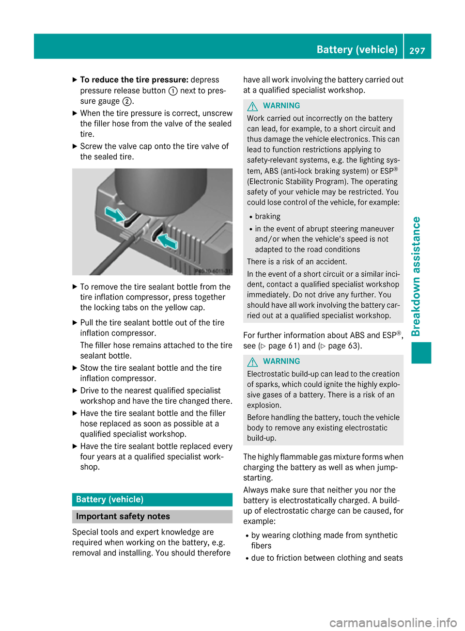
X
To reduce the tire pressure: depress
pressure release button 0043next to pres-
sure gauge 0044.
X When the tire pressure is correct, unscrew
the filler hose from the valve of the sealed
tire.
X Screw the valve cap onto the tire valve of
the sealed tire. X
To remove the tire sealant bottle from the
tire inflation compressor, press together
the locking tabs on the yellow cap.
X Pull the tire sealant bottle out of the tire
inflation compressor.
The filler hose remains attached to the tire
sealant bottle.
X Stow the tire sealant bottle and the tire
inflation compressor.
X Drive to the nearest qualified specialist
workshop and have the tire changed there.
X Have the tire sealant bottle and the filler
hose replaced as soon as possible at a
qualified specialist workshop.
X Have the tire sealant bottle replaced every
four years at a qualified specialist work-
shop. Battery (vehicle)
Important safety notes
Special tools and expert knowledge are
required when working on the battery, e.g.
removal and installing. You should therefore have all work involving the battery carried out
at a qualified specialist workshop. G
WARNING
Work carried out incorrectly on the battery
can lead, for example, to a short circuit and
thus damage the vehicle electronics. This can lead to function restrictions applying to
safety-relevant systems, e.g. the lighting sys-
tem, ABS (anti-lock braking system) or ESP ®
(Electronic Stability Program). The operating
safety of your vehicle may be restricted. You
could lose control of the vehicle, for example:
R braking
R in the event of abrupt steering maneuver
and/or when the vehicle's speed is not
adapted to the road conditions
There is a risk of an accident.
In the event of a short circuit or a similar inci- dent, contact a qualified specialist workshop
immediately. Do not drive any further. You
should have all work involving the battery car-
ried out at a qualified specialist workshop.
For further information about ABS and ESP ®
,
see (Y page 61) and (Y page 63). G
WARNING
Electrostatic build-up can lead to the creation of sparks, which could ignite the highly explo-
sive gases of a battery. There is a risk of an
explosion.
Before handling the battery, touch the vehicle body to remove any existing electrostatic
build-up.
The highly flammable gas mixture forms when
charging the battery as well as when jump-
starting.
Always make sure that neither you nor the
battery is electrostatically charged. A build-
up of electrostatic charge can be caused, for
example:
R by wearing clothing made from synthetic
fibers
R due to friction between clothing and seats Battery (vehicle)
297Breakdown assis tance Z
Page 317 of 358

Example: tire pressure table with tire dimensions
If a tire size precedes a tire pressure, the tirepressure information following is only valid
for that tire size. The load conditions "partially
laden" and "fully laden" are defined in the
table for different numbers of occupants and
amounts of luggage. The actual number of
seats may differ. Some tire pressure tables show only the rim
diameters instead of the full tire size, e.g.
R18 . The rim diameter is part of the tire size
and can be found on the tire sidewall
(Y page 326).
If the tire pressures have been set to the
lower values for lighter loads and/or lower
road speeds, the pressures should be reset to the higher values:
R if you want to drive with an increased load
and/or
R if you want to drive at higher road speeds.
i The tire pressures for increased loads
and/or higher road speeds, shown in the
tire pressure table, may have a negative
effect on driving comfort. If the tire pressure is not set correctly, this
can lead to an excessive build up of heat and
a sudden loss of pressure.
For more information, contact a qualified spe- cialist workshop. Important notes on tire pressure
G
WARNING
If the tire pressure drops repeatedly, the
wheel, valve or tire may be damaged. Tire
pressure that is too low may result in a tire
blow-out. There is a risk of an accident. R Check the tire for foreign objects.
R Check whether the wheel is losing air or the
valve is leaking.
If you are unable to rectify the damage, con-
tact a qualified specialist workshop. G
WARNING
If you fit unsuitable accessories onto tire
valves, the tire valves may be overloaded and malfunction, which can cause tire pressure
loss. Due to their design, retrofitted tire pres- sure monitors keep the tire valve open. This
can also result in tire pressure loss. There is a
risk of an accident.
Only screw the standard valve cap or other
valve caps approved by Mercedes-Benz for
your vehicle onto the tire valve.
Use a suitable pressure gauge to check the
tire pressure. The outer appearance of a tire
does not permit any reliable conclusion about the tire pressure. On vehicles equipped with
the electronic tire pressure monitoring sys-
tem, the tire pressure can be checked using
the on-board computer.
The tire temperature and pressure increase
when the vehicle is in motion. This is depend-
ent on the driving speed and the load.
Therefore, you should only correct tire pres-
sures when the tires are cold. Tire pressure
315Wheels and tires Z