2015 MERCEDES-BENZ SLK-Class clock
[x] Cancel search: clockPage 137 of 358

Setting the side air vents
0043
Side window defroster vent
0044 Side air vent
X To open a side air vent: turn the adjuster
in side air vent 0044counter-clockwise.
X To close a side air vent: turn the adjuster
in side air vent 0044clockwise until it
engages. Setting the blower output of the AIR-
SCARF vents G
WARNING
Very hot or very cold air can flow from the air vents. This could result in burns or frostbite in the immediate vicinity of the air vents. There
is a risk of injury.
Make sure that all vehicle occupants always
maintain a sufficient distance to the air out-
lets. If necessary, redirect the airflow to
another area of the vehicle interior. G
WARNING
When AIRSCARF is switched on, very hot air
can flow from the vents in the head restraints. This could result in burns in the immediate
vicinity of the air vents. There is a risk of injury.
Reduce the heater output before it becomes
too hot. You can adjust the blower output of AIR-
SCARF vents
0043using the AIRSCARF button
(Y page 100). Setting the air vents
135Climate control Z
Page 162 of 358
X
Switch the engine off.
X Remove the SmartKey from the ignition
lock.
X Press the fuel filler flap in the direction of
arrow 0043.
The fuel filler flap swings up.
X Turn the fuel filler flap counter-clockwise
and remove it.
X Insert the fuel filler cap into the holder
bracket on the inside of fuel filler flap 0044.
X Completely insert the filler neck of the fuel
pump nozzle into the tank, hook in place
and refuel.
X Only fill the tank until the pump nozzle
switches off.
i Do not add any more fuel after the pump
stops filling for the first time. Otherwise,
fuel may leak out.
Closing the fuel filler flap X
Place fuel filler cap on the fuel filler neck
and turn clockwise until it engages.
X Close fuel filler flap 0043.
i Close the fuel filler flap before locking the
vehicle.
i If you are driving with the fuel filler cap
open, the 00B6reserve fuel warning lamp
flashes. The 00B9Check Engine warning
lamp may also light up. A message appears in the multifunction display (Y page 231).
For further information on warning and indi-
cator lamps in the instrument cluster, see
(Y page 251). 160
RefuelingDriving and parking
Page 196 of 358
Useful information
i This Operator's manual describes all
models and all standard and optional equip- ment of your vehicle available at the time of
publication of the Operator's manual.
Country-specific differences are possible.
Please note that your vehicle may not be
equipped with all features described. This
also applies to safety-related systems and
functions.
i Read the information on qualified special-
ist workshops (Y page 26). Important safety notes
G
WARNING
If you operate information systems and com-
munication equipment integrated in the vehi- cle while driving, you will be distracted from
traffic conditions. You could also lose control of the vehicle. There is a risk of an accident.
Only operate the equipment when the traffic
situation permits. If you are not sure that this
is possible, park the vehicle paying attention
to traffic conditions and operate the equip-
ment when the vehicle is stationary.
You must observe the legal requirements for
the country in which you are currently driving when operating the on-board computer. G
WARNING
If the instrument cluster has failed or mal-
functioned, you may not recognize function
restrictions in systems relevant to safety. The operating safety of your vehicle may be
impaired. There is a risk of an accident.
Drive on carefully. Have the vehicle checked
at a qualified specialist workshop immedi-
ately.
The on-board computer only shows messages
or warnings from certain systems in the mul- tifunction display. You should therefore make
sure your vehicle is operating safely at all times. Otherwise, a vehicle that is not oper-
ating safely may cause an accident.
If the operating safety of your vehicle is
impaired, pull over as soon as it is safe to do
so. Contact a qualified specialist workshop.
For an overview, see the instrument panel
illustration (Y
page 31). Displays and operation
Instrument cluster lighting
The lighting in the instrument cluster, in the
displays and the controls in the vehicle inte-
rior can be adjusted using the brightness con-
trol knob.
The brightness control knob is on the bottom left of the instrument cluster (Y page 31).
X Turn the brightness control knob counter-
clockwise or clockwise.
If the light switch is set to 0058,0060or
0058, the brightness is dependent upon
the brightness of the ambient light.
i The light sensor in the instrument cluster
automatically controls the brightness of
the multifunction display.
In daylight, the displays in the instrument
cluster are not lit. Coolant temperature display
G
WARNING
Opening the hood when the engine is over-
heated or when there is a fire in the engine
compartment could expose you to hot gases
or other service products. There is a risk of
injury.
Let an overheated engine cool down before
opening the hood. If there is a fire in the
engine compartment, keep the hood closed
and contact the fire department.
! A display message is shown if the coolant
temperature is too high. 194
Displays and operationOn-board computer and displays
Page 209 of 358

Vehicle
Activating/deactivating the automatic
door locking mechanism
X Press the 0059or0065 button on the steer-
ing wheel to select the Sett Settmenu.
X Press the 0064or0063 button to select the
Vehicle
Vehicle submenu.
X Press 0076to confirm.
X Press the 0064or0063 button to select the
Automatic Door Lock
Automatic Door Lock function.
When the Automatic
Automatic Door
DoorLock
Lockfunction
is activated, the left-hand vehicle door is
displayed in orange in the multifunction
display.
X Press the 0076button to save the setting.
If you activate the Automatic Door Lock
Automatic Door Lock
function, the vehicle is centrally locked above
a speed of around 9 mph (15 km/h).
For further information on the automatic lock- ing feature, see (Y page 79).
Activating/deactivating the acoustic
locking verification signal
If you switch on the Acoustic AcousticLock
Lockfunction,
an acoustic signal sounds when you lock the
vehicle.
X Press the 0059or0065 button on the steer-
ing wheel to select the Sett
Sett menu.
X Press the 0064or0063 button to select the
Vehicle
Vehicle submenu.
X Press 0076to confirm.
X Press the 0064or0063 button to select the
Acoustic Lock
Acoustic Lock function.
If the Acoustic
Acoustic Lock
Lockfunction is activated,
the 0037 symbol in the multifunction dis-
play lights up orange.
X Press the 0076button to save the setting.
Activating/deactivating the radar sensor
system
X Press the 0059or0065 button on the steer-
ing wheel to select the Settings
Settings menu.
X Press the 0064or0063 button to select the
Vehicle
Vehicle submenu. X
Press 0076to confirm.
X Press the 0063or0064 button to select
Radar Sensor (See Oper. Manual):
Radar Sensor (See Oper. Manual):.
You will see the selected setting: Enabled Enabled
or Disabled
Disabled.
X Press the 0076button to save the setting.
The following systems are switched off when
the radar sensor system is deactivated:
R DISTRONIC PLUS (Y page 171)
R BAS PLUS (Y page 62)
R PRE-SAFE ®
Brake (Y page 67)
Convenience Activating/deactivating the EASY-
ENTRY/EXIT feature G
WARNING
When the EASY-ENTRY/EXIT feature adjusts
the steering wheel, you and other vehicle
occupants – particularly children – could
become trapped. There is a risk of injury.
While the EASY-ENTRY/EXIT feature is mak-
ing adjustments, make sure that no one has
any body parts in the sweep of the steering
wheel.
If somebody becomes trapped:
R press one of the memory function position
buttons, or
R move the switch for steering wheel adjust-
ment in the opposite direction to that in
which the steering wheel is moving.
The adjustment process is stopped.
X Press the 0059or0065 button on the steer-
ing wheel to select the Sett Settmenu.
X Press the 0064or0063 button to select the
Convenience
Convenience submenu.
X Press 0076to confirm.
X Press the 0064or0063 button to select the
Easy Entry/Exit
Easy Entry/Exit function.
If the Easy Entry/Exit
Easy Entry/Exit function is activa-
ted, the vehicle steering wheel is displayed
in orange in the multifunction display.
X Press the 0076button to save the setting. Menus and submenus
207On-board computer and displays Z
Page 282 of 358
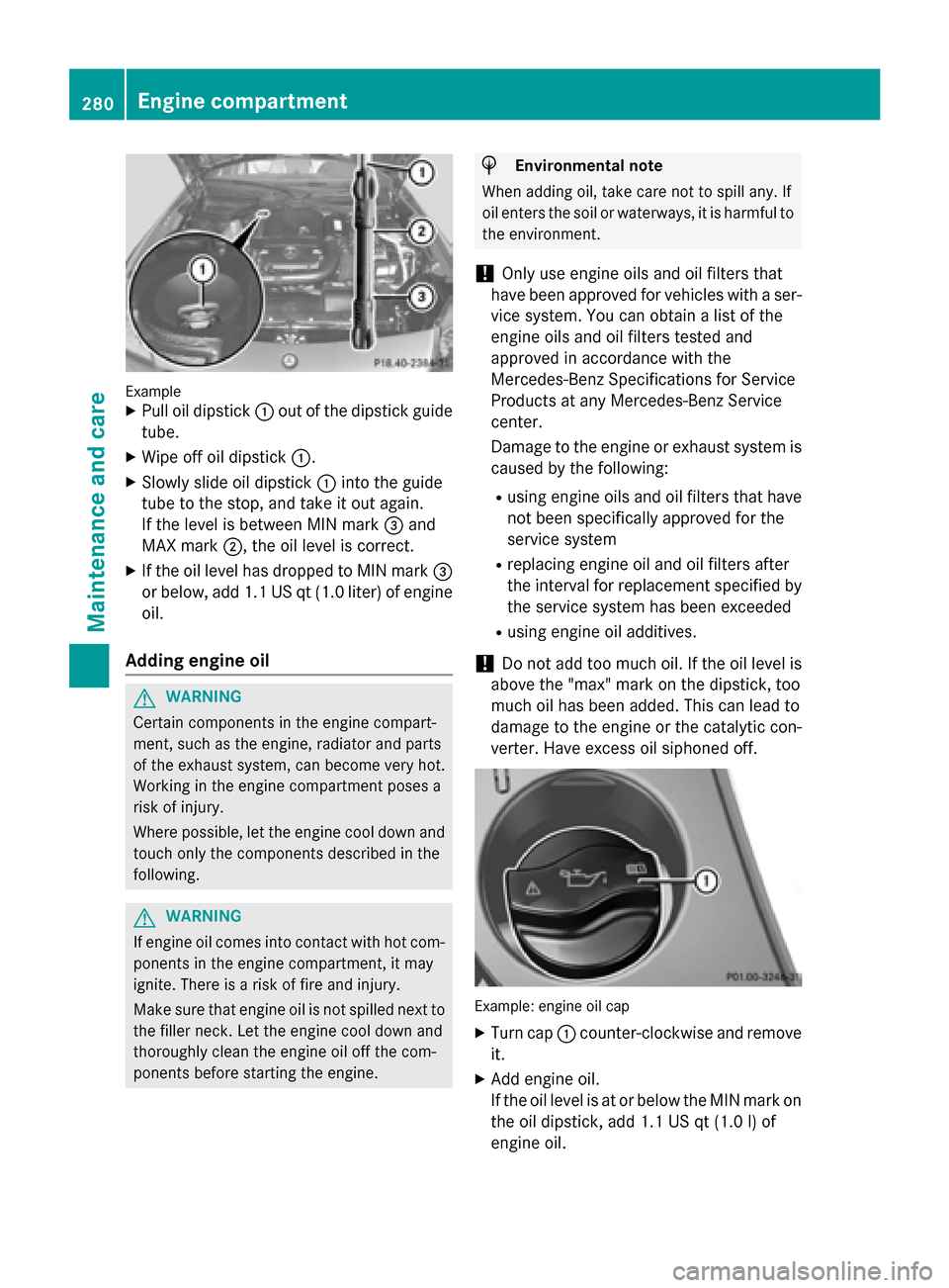
Example
X Pull oil dipstick 0043out of the dipstick guide
tube.
X Wipe off oil dipstick 0043.
X Slowly slide oil dipstick 0043into the guide
tube to the stop, and take it out again.
If the level is between MIN mark 0087and
MAX mark 0044, the oil level is correct.
X If the oil level has dropped to MIN mark 0087
or below, add 1.1 US qt (1.0 liter) of engine oil.
Adding engine oil G
WARNING
Certain components in the engine compart-
ment, such as the engine, radiator and parts
of the exhaust system, can become very hot.
Working in the engine compartment poses a
risk of injury.
Where possible, let the engine cool down and touch only the components described in the
following. G
WARNING
If engine oil comes into contact with hot com- ponents in the engine compartment, it may
ignite. There is a risk of fire and injury.
Make sure that engine oil is not spilled next to
the filler neck. Let the engine cool down and
thoroughly clean the engine oil off the com-
ponents before starting the engine. H
Environmental note
When adding oil, take care not to spill any. If
oil enters the soil or waterways, it is harmful to the environment.
! Only use engine oils and oil filters that
have been approved for vehicles with a ser-
vice system. You can obtain a list of the
engine oils and oil filters tested and
approved in accordance with the
Mercedes-Benz Specifications for Service
Products at any Mercedes-Benz Service
center.
Damage to the engine or exhaust system is caused by the following:
R using engine oils and oil filters that have
not been specifically approved for the
service system
R replacing engine oil and oil filters after
the interval for replacement specified by
the service system has been exceeded
R using engine oil additives.
! Do not add too much oil. If the oil level is
above the "max" mark on the dipstick, too
much oil has been added. This can lead to
damage to the engine or the catalytic con-
verter. Have excess oil siphoned off. Example: engine oil cap
X Turn cap 0043counter-clockwise and remove
it.
X Add engine oil.
If the oil level is at or below the MIN mark on
the oil dipstick, add 1.1 US qt (1.0 l)of
engine oil. 280
Engine compartmentMaintenance and care
Page 283 of 358
X
Replace cap 0043on the filler neck and turn
clockwise.
Ensure that the cap locks into place
securely.
X Check the oil level again with the oil dip-
stick (Y page 279).
Further information on engine oil
(Y page 349). Checking and adding other service
products
Checking coolant level G
WARNING
Certain components in the engine compart-
ment, such as the engine, radiator and parts
of the exhaust system, can become very hot.
Working in the engine compartment poses a
risk of injury.
Where possible, let the engine cool down and touch only the components described in the
following. G
WARNING
The engine cooling system is pressurized, par- ticularly when the engine is warm. When
opening the cap, you could be scalded by hotcoolant spraying out. There is a risk of injury.
Let the engine cool down before opening the
cap. Wear eye and hand protection when
opening the cap. Open the cap slowly half a
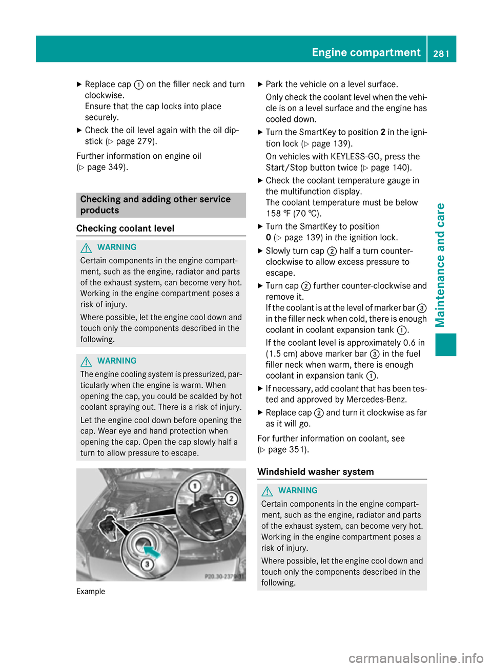
turn to allow pressure to escape. Example X
Park the vehicle on a level surface.
Only check the coolant level when the vehi- cle is on a level surface and the engine has
cooled down.
X Turn the SmartKey to position 2in the igni-
tion lock (Y page 139).
On vehicles with KEYLESS-GO, press the
Start/Stop button twice (Y page 140).
X Check the coolant temperature gauge in
the multifunction display.
The coolant temperature must be below
158 ‡ (70 †).
X Turn the SmartKey to position
0(Y page 139) in the ignition lock.
X Slowly turn cap 0044half a turn counter-
clockwise to allow excess pressure to
escape.
X Turn cap 0044further counter-clockwise and
remove it.
If the coolant is at the level of marker bar 0087
in the filler neck when cold, there is enough coolant in coolant expansion tank 0043.
If the coolant level is approximately 0.6 in
(1.5 cm) above marker bar 0087in the fuel
filler neck when warm, there is enough
coolant in expansion tank 0043.
X If necessary, add coolant that has been tes-
ted and approved by Mercedes-Benz.
X Replace cap 0044and turn it clockwise as far
as it will go.
For further information on coolant, see
(Y page 351).
Windshield washer system G
WARNING
Certain components in the engine compart-
ment, such as the engine, radiator and parts
of the exhaust system, can become very hot.
Working in the engine compartment poses a
risk of injury.
Where possible, let the engine cool down and touch only the components described in the
following. Engine compartment
281Maintenance and care Z
Page 301 of 358

Risk of explosion.
Fire, open flames and smoking are
prohibited when handling the bat-
tery. Avoid creating sparks. Battery acid is caustic. Avoid con-
tact with skin, eyes or clothing.
Wear suitable protective clothing,
especially gloves, apron and face-
guard.
Rinse any acid spills immediately
with clear water. Contact a physi-
cian if necessary. Wear eye protection.
Keep children away.
Observe this Operator's Manual.
The vehicle battery, like other batteries, can
discharge over time if you do not use the
vehicle. In this case, have the battery discon-
nected at a qualified specialist workshop. You can also charge the battery with a charger
recommended by Mercedes-Benz. Contact a
qualified specialist workshop for further infor-
mation.
Have the battery condition of charge checked
more frequently if you use the vehicle mainly for short trips or if you leave it standing idle
for a lengthy period. Consult a qualified spe-
cialist workshop if you wish to leave your
vehicle parked for a long period of time.
i Remove the SmartKey if you park the
vehicle and do not require any electrical
consumers. The vehicle will then use very
little energy, thus conserving battery
power. i
If the power supply has been interrupted,
e.g. if you reconnect the battery, you will
have to:
R set the clock; see the separate operating
instructions.
On vehicles with COMAND and a naviga-
tion system, the clock is set automati-
cally.
R reset the function for folding the exterior
mirrors in/out automatically, by folding
the mirrors out once (Y page 104). Charging the battery
G
WARNING
During charging and jump-starting, explosive
gases can escape from the battery. There is a risk of an explosion.
Particularly avoid fire, open flames, creating
sparks and smoking. Ensure there is sufficient
ventilation while charging and jump-starting.
Do not lean over a battery. G
WARNING
Battery acid is caustic. There is a risk of injury. Avoid contact with the skin, eyes or clothing.
Do not inhale any battery gases. Do not lean
over the battery. Keep children away from
batteries. Wash battery acid immediately with water and seek medical attention. G
WARNING
A discharged battery can freeze at tempera-
tures below freezing point. When jump-start-
ing the vehicle or charging the battery, gases can escape from the battery. There is a risk of
an explosion.
Allow the frozen battery to thaw out before
charging it or jump-starting.
! Only use battery chargers with a maxi-
mum charging voltage of 14.8 V.
! Only charge the battery using the jump-
starting connection point. Battery (vehicle)
299Breakdown assistance Z
Page 306 of 358
ignition lock and shift the automatic trans-
mission to N. Then, turn the SmartKey back
to 0and leave it in the ignition lock.
! Make sure that the electric parking brake
is released. If the electric parking brake is
faulty, visit a qualified specialist workshop.
! The vehicle can be towed a maximum of
30 miles (50km). The to wing speed of
30 mph (50 km/h) must not be exceeded.
If the vehicle has to be towed more than
30 miles (50km), the entire vehicle must be
raised and transported.
! If you tow or tow-start another vehicle, its
weight must not exceed the maximum per- missible gross vehicle weight of your vehi-
cle.
i Information on your vehicle's gross vehi-
cle weight rating can be found on the vehi-
cle identification plate (Y page 346).
It is better to have the vehicle transported
than to have it towed.
Vehicles with automatic transmission:
when towing a vehicle, the automatic trans-
mission must be in position N.
The battery must be connected and charged. Otherwise, you:
R cannot turn the SmartKey to position 2in
the ignition lock
R cannot shift the transmission to position N
on vehicles with automatic transmission
Vehicles with automatic transmission:
release the selector lever lock manually to
move it out of position P(Y page 158).
i Disarm the automatic locking feature
before the vehicle is towed (Y page 207).
You could otherwise be locked out when
pushing or towing the vehicle. Installing/removing the towing eye
Installing the towing eye G
WARNING
The exhaust tail pipe may be very hot. There is
a risk of burns when removing the rear cover.
Do not touch the exhaust pipe. Take particular
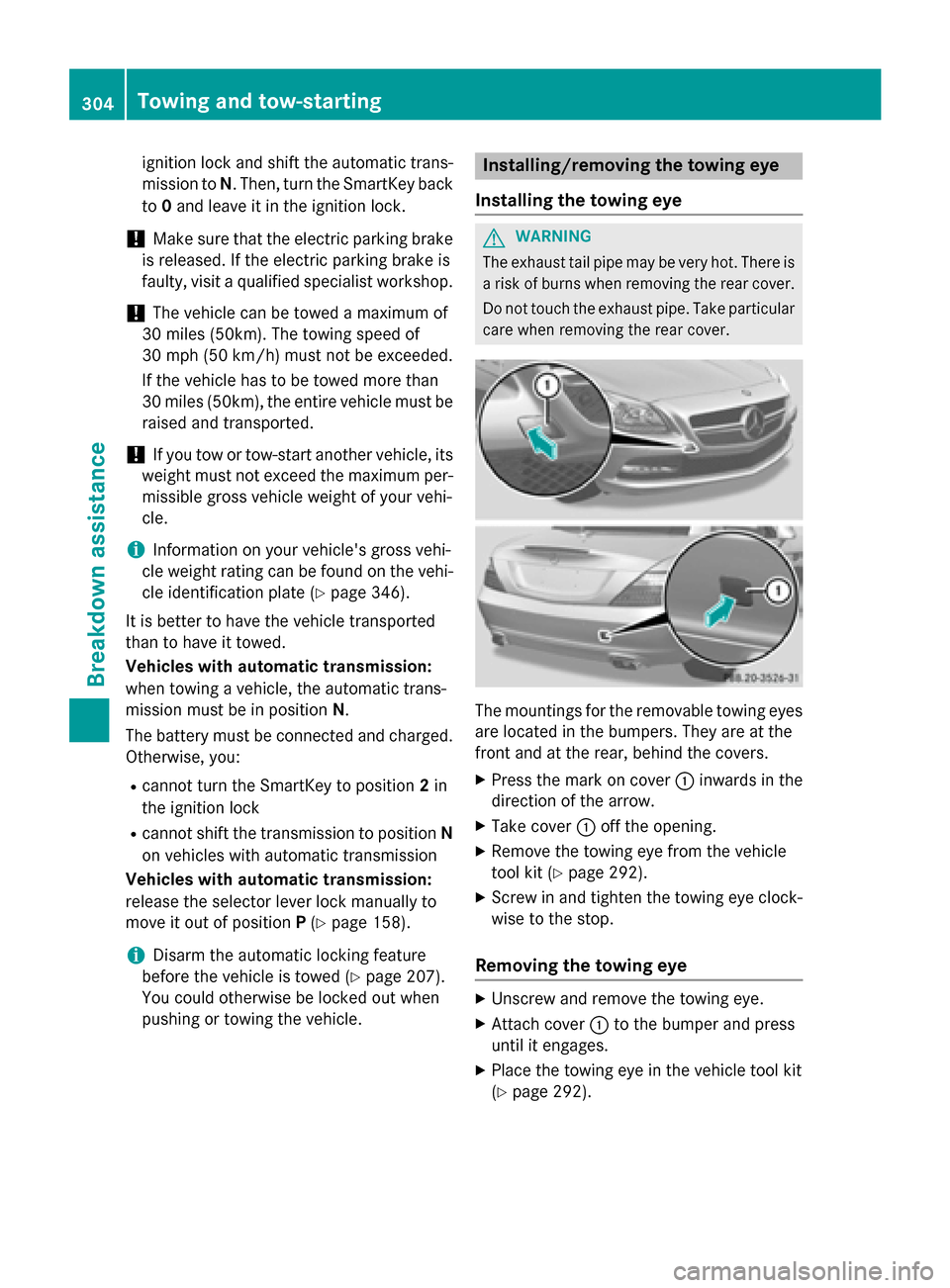
care when removing the rear cover. The mountings for the removable towing eyes
are located in the bumpers. They are at the
front and at the rear, behind the covers.
X Press the mark on cover 0043inwards in the
direction of the arrow.
X Take cover 0043off the opening.
X Remove the towing eye from the vehicle
tool kit (Y page 292).
X Screw in and tighten the towing eye clock-
wise to the stop.
Removing the towing eye X
Unscrew and remove the towing eye.
X Attach cover 0043to the bumper and press
until it engages.
X Place the towing eye in the vehicle tool kit
(Y page 292). 304
Towing and tow-startingBreakdown assistance