2015 MERCEDES-BENZ S-CLASS COUPE tow bar
[x] Cancel search: tow barPage 215 of 417

X
If indicator lamp ;
;is not lit: press but-
ton :.
Indicator lamp ;lights up. You have selec-
ted "Comfort mode".
All vehicles except AMG vehicles: the
AIRMATIC COMFORT AIRMATIC COMFORT message appears in
the multifunction display.
AMG vehicles: theAMG Ride Control AMG Ride Control
COMFORT
COMFORT message appears in the multi-
function display.
All vehicles except AMG vehicles: if the
driving speed is higher than 160 km/h, the
vehicle is automatically lowered by 10 mm.
Load compensation The vehicle can compensate differences in
the vehicle level by raising or lowering the
axles. 4MATIC (permanent all-wheel drive)
4MATIC ensures that all four wheels are per-
manently driven. Together with ESP ®
, it
improves the traction of your vehicle when-
ever a drive wheel spins due to insufficient
grip.
If you fail to adapt your driving style, 4MATIC
can neither reduce the risk of accident nor
override the laws of physics. 4MATIC cannot
take account of road, weather and traffic con- ditions. 4MATIC is only an aid. You are
responsible for the distance to the vehicle in
front, for vehicle speed, for braking in good
time, and for staying in the lane.
If a drive wheel spins due to insufficient grip:
R when pulling away, only depress the accel-
erator pedal as far as is necessary.
R accelerate less when driving
! Never tow the vehicle with one axle
raised. This may damage the transfer case.
Damage of this sort is not covered by the
Mercedes-Benz implied warranty. All
wheels must remain either on the ground or be fully raised. Observe the instructions for towing the vehicle with all wheels in full
contact with the ground.
i In wintry driving conditions, the maximum
effect of 4MATIC can only be achieved if
you use winter tyres (M+S tyres),with snow
chains if necessary. PARKTRONIC
Important safety notes PARKTRONIC is an electronic parking aid with
ultrasonic sensors. It monitors the area
around your vehicle using six sensors in the
front bumper and six sensors in the rear
bumper. PARKTRONIC indicates visually and
audibly the distance between your vehicle
and an object.
PARKTRONIC is only an aid. It is not a substi-
tute for your attention to the immediate sur-
roundings. The responsibility for safe
manoeuvring and parking remains with you.
Make sure that there are no persons, animals
or objects in range while manoeuvring and
parking.
! When parking, pay particular attention to
objects above or below the sensors, such
as flower pots or trailer drawbars.
PARKTRONIC does not detect such objects
when they are in the immediate vicinity of
the vehicle. You could damage the vehicle
or the objects.
The sensors may not detect snow and
objects which absorb ultrasonic sources.
Ultrasonic sources, such as an automatic
car wash, a lorry's compressed-air brakes
or a pneumatic drill, could cause
PARKTRONIC to malfunction.
PARKTRONIC may not function correctly on uneven terrain.
PARKTRONIC is activated automatically when you:
R switch on the ignition
R shift the transmission to position D,Ror N 212
Driving systemsDriving and parking
Page 224 of 417
Activating/deactivating the reversing
camera X
To activate: make sure that the key is in
position 2in the ignition lock.
X Make sure that the Activation by R
Activation by R
gear
gear function is selected in COMAND
Online (see separate operating instruc-
tions).
X Engage reverse gear.
The reversing camera flap opens. The area
behind the vehicle is shown with guide lines in the COMAND display.
The image from the reversing camera is
available throughout the manoeuvring
process.
To deactivate: the reversing camera deacti-
vates if you shift the transmission to Por after
driving forwards a short distance.
Displays in the COMAND display The reversing camera may show a distorted
view of obstacles or show them incorrectly or not at all. Obstacles are not shown by the
reversing camera in the following locations:
R very close to the rear bumper
R under the rear bumper
R in the area immediately above the emblem
in the boot lid.
! Objects not at ground level may appear to
be further away than they actually are, e.g.:
R the bumper of a parked vehicle
R the drawbar of a trailer
R the ball coupling of a trailer tow hitch
R the rear section of an HGV
R a slanted post
Use the guidelines only for orientation.
Approach objects no further than the bot-
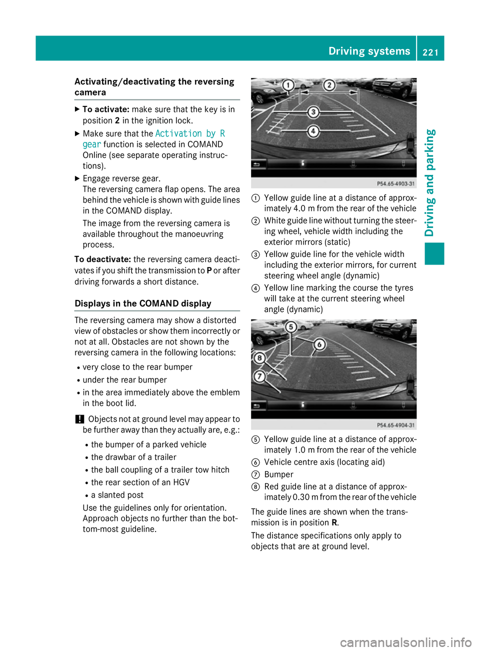
tom-most guideline. :
Yellow guide line at a distance of approx-
imately 4.0 mfrom the rear of the vehicle
; White guide line without turning the steer-
ing wheel, vehicle width including the
exterior mirrors (static)
= Yellow guide line for the vehicle width
including the exterior mirrors, for current
steering wheel angle (dynamic)
? Yellow line marking the course the tyres
will take at the current steering wheel
angle (dynamic) A
Yellow guide line at a distance of approx-
imately 1.0 mfrom the rear of the vehicle
B Vehicle centre axis (locating aid)
C Bumper
D Red guide line at a distance of approx-
imately 0.30 mfrom the rear of the vehicle
The guide lines are shown when the trans-
mission is in position R.
The distance specifications only apply to
objects that are at ground level. Driving systems
221Driving and parking Z
Page 229 of 417
R
full-screen view with image from the
front camera
R full-screen view with image from the
reversing camera.
X To switch off: press button:again.
Activating the 360° camera using
COMAND Online X
Press the Øbutton in the centre con-
sole.
The vehicle menu appears.
X To select the 360° camera: turn and press
the controller.
The following appears depending on
whether transmission position Dor Ris
selected:
R a split-screen with top view and the
image from the front camera or
R a split-screen with top view and the
image from the reversing camera.
Further information on the COMAND control-
ler can be found in the separate operating
instructions.
Activating the 360° camera using
reverse gear You can show images from the 360° camera
automatically by engaging reverse gear.
X Make sure that the key is in position 2in the
ignition lock.
X Make sure that the Activation by R Activation by R
gear
gear function is selected in COMAND
Online (see separate operating instruc-
tions).
X To show the 360° camera image: engage
reverse gear.
The area behind the vehicle is shown in the
COMAND display in split-screen mode. You see the top view of the vehicle and the
image from the reversing camera. Selecting the split-screen and full
screen displays Switching between split screen views:
X To switch to the line with the vehicle icons:
slide ZVthe controller.
X To select a vehicle icon: turn the controller.
Switching to full screen mode:
X Select 180° view
180° view by turning and pressing
the controller.
i The 180° option is only available in the
following views:
R Top view with image from the reversing
camera
R Top view with image from the front cam-
era
Displays in the COMAND display Important safety notes
The camera system may show a distorted
view of obstacles or show them incorrectly or
not at all. Obstacles are not shown by the
system in the following locations:
R under the front and rear bumpers
R very close to the front and rear bumpers
R in the area immediately above the handle
on the boot lid
R very close to the exterior mirrors
R in the transitional areas between the vari-
ous cameras in the virtual top view
! Objects not at ground level may appear to
be further away than they actually are, e.g.:
R the bumper of a parked vehicle
R the drawbar of a trailer
R the ball coupling of a trailer tow hitch
R the rear section of an HGV
R a slanted post
Use the guidelines only for orientation.
Approach objects no further than the bot-
tom-most guideline. 226
Driving systemsDriving an
d parking
Page 338 of 417
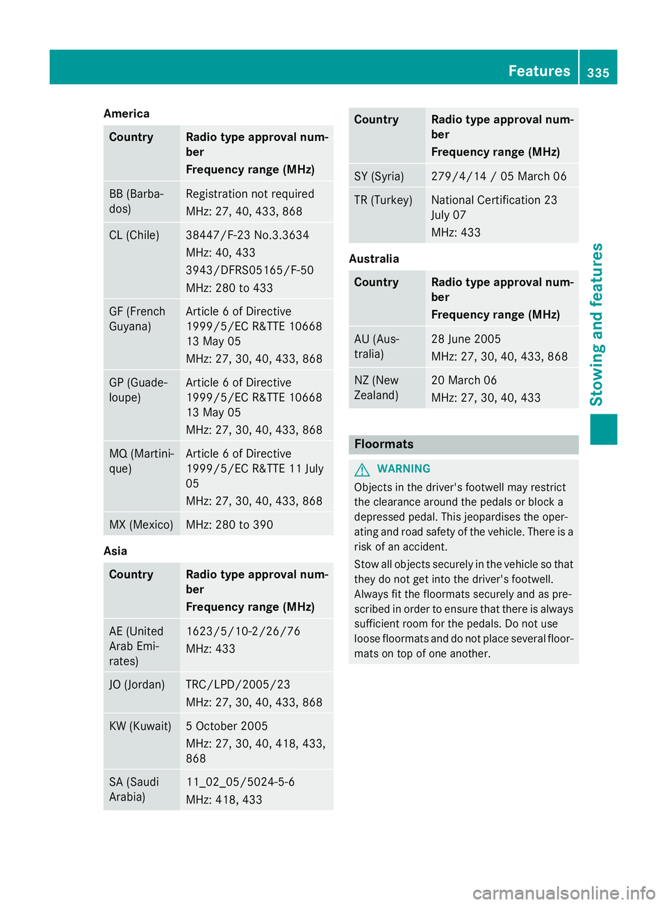
America
Country Radio type approval num-
ber
Frequency range (MHz)
BB (Barba-
dos) Registration not required
MHz: 27, 40, 433, 868
CL (Chile) 38447/F-23 No.3.3634
MHz: 40, 433
3943/DFRS05165/F-50
MHz: 280 to 433
GF (French
Guyana) Article 6 of Directive
1999/5/EC R&TTE 10668
13 May 05
MHz: 27, 30, 40, 433, 868
GP (Guade-
loupe) Article 6 of Directive
1999/5/EC R&TTE 10668
13 May 05
MHz: 27, 30, 40, 433, 868
MQ (Martini-
que) Article 6 of Directive
1999/5/EC R&TTE 11 July
05
MHz: 27, 30, 40, 433, 868
MX (Mexico) MHz: 280 to 390
Asia
Country Radio type approval num-
ber
Frequency range (MHz)
AE (United
Arab Emi-
rates) 1623/5/10-2/26/76
MHz: 433
JO (Jordan) TRC/LPD/2005/23
MHz: 27, 30, 40, 433, 868
KW (Kuwait) 5 October 2005
MHz: 27, 30, 40, 418, 433,
868
SA (Saudi
Arabia) 11_02_05/5024-5-6
MHz: 418, 433 Country Radio type approval num-
ber
Frequency range (MHz)
SY (Syria) 279/4/14 / 05 March 06
TR (Turkey) National Certification 23
July 07
MHz: 433
Australia
Country Radio type approval num-
ber
Frequency range (MHz)
AU (Aus-
tralia) 28 June 2005
MHz: 27, 30, 40, 433, 868
NZ (New
Zealand) 20 March 06
MHz: 27, 30, 40, 433
Floormats
G
WARNING
Objects in the driver's footwell may restrict
the clearance around the pedals or block a
depressed pedal. This jeopardises the oper-
ating and road safety of the vehicle. There is a risk of an accident.
Stow all objects securely in the vehicle so that
they do not get into the driver's footwell.
Always fit the floormats securely and as pre-
scribed in order to ensure that there is always sufficient room for the pedals. Do not use
loose floormats and do not place several floor-mats on top of one another. Features
335Stowing and featu res Z
Page 364 of 417
X
Press on and off switch =on the tyre infla-
tion compressor to I.
The tyre inflation compressor is switched
on. The tyre is inflated.
i First, tyre sealant is pumped into the tyre.
The pressure may briefly rise to approx-
imately 500 kPa (5 bar/73 psi).
Do not switch off the tyre inflation com-
pressor during this phase.
X Let the tyre inflation compressor run for
five minutes. The tyre should then have
attained a pressure of at least 180 kPa
(1.8 bar/26 psi).
If a pressure of 180 kPa (1.8 bar/26 psi) has been attained after five minutes, see "Tyre
pressure reached" (Y page 361).
If a tyre pressure of 180 kPa (1.8 bar/26 psi)
has not been attained after five minutes, see "Tyre pressure not reached" (Y page 361).
i If the tyre sealant leaks out, allow it to dry.
It can then be removed like a layer of film.
If you get tyre sealant on your clothing,
have it cleaned as soon as possible with
perchloroethylene.
Tyre pressure not reached If a pressure of 180 kPa (1.8 bar/26 psi) has
not been attained after five minutes:
X Switch off the tyre inflation compressor.
X Unscrew the filler hose from the valve of
the faulty tyre.
X Very slowly drive forwards or reverse
approximately 10 m.
X Pump up the tyre again.
After a maximum of five minutes the tyre
pressure must be at least 180 kPa (1.8 bar/ 26 psi). G
WARNING
If the required tyre pressure is not reached
after the specified time, the tyre is too badly
damaged. The tyre sealant cannot repair the
tyre in this instance. Damaged tyres and a tyre pressure that is too low can significantly impair the vehicle's braking and driving char-
acteristics. There is a risk of accident.
Do not continue driving. Contact a qualified
specialist workshop.
Tyre pressure reached G
WARNING
A tyre temporarily sealed with tyre sealant
impairs the driving characteristics and is not
suitable for higher speeds. There is a risk of
accident.
You should therefore adapt your driving style
accordingly and drive carefully. Do not exceed the specified maximum speed with a tyre that
has been repaired using tyre sealant.
The maximum speed for a tyre sealed with
tyre sealant is 80 km/h. The upper part of the
TIREFIT sticker must be affixed to the instru-
ment cluster where it will be easily seen by
the driver.
! After use, excess tyre sealant may run out
of the filler hose. This could cause stains.
Therefore, place the filler hose in the plastic
bag which contained the TIREFIT kit. H
Environmental note
Have the used tyre sealant bottle disposed of professionally, e.g. at a qualified specialist
workshop.
If a tyre pressure of 180 kPa (1.8 bar/26 psi)
has been attained after five minutes:
X Switch off the tyre inflation compressor.
X Unscrew the filler hose from the valve of
the faulty tyre.
X Stow the tyre sealant bottle, the tyre infla-
tion compressor and the warning triangle.
X Pull away immediately.
X Stop after driving for approximately ten
minutes and check the tyre pressure with
the tyre inflation compressor.
The tyre pressure must now be at least
130 kPa (1.3 bar/19 psi). Flat tyre
361Breakdown assistance Z
Page 372 of 417
X
First, remove the jump leads from earth point Band negative terminal A, then from pos-
itive clamp =and positive terminal ?. Begin each time at the contacts on your own vehicle
first.
X Close cover Cof positive clamp =after removing the jump leads.
X Replace the earth point cover. Make sure all mountings for the fasteners are positioned
precisely beneath the corresponding recesses in the cover.
X Press fasteners :into the mountings until they engage.
X Have the battery checked at a qualified specialist workshop.
Jump-starting is not considered to be a normal operating condition.
i Jump-starting cables and further information regarding jump starting can be obtained at
any qualified specialist workshop. Towing away and tow-starting
Important safety notes
G
WARNING
Safety-relevant functions are restricted or not
available if:
R the engine is not running.
R the brake system or the power steering is
malfunctioning
R the voltage supply or the vehicle's electrical
system is malfunctioning.
If your vehicle is towed, significantly greater
force may be required to steer the vehicle or
to brake. There is a risk of an accident.
In such circumstances, use a towing bar.
Make sure that the steering is moving freely
before towing. G
WARNING
If the steering wheel lock is engaged, the vehi- cle can no longer be steered. There is a risk of
an accident.
Always switch on the ignition when towing
with a tow rope or a towing bar. G
WARNING
When towing or tow-starting another vehicle
and its weight is greater than the permissible gross weight of your vehicle, the:
R towing eye may be torn off
R car/trailer combination may swerve or
even overturn
There is a risk of an accident.
When towing or tow-starting another vehicle,
its weight should not be greater than the per- missible gross weight of your vehicle.
Information on your vehicle's gross vehicle
weight rating can be found on the vehicle
identification plate (Y page 404).
! When COLLISION PREVENTION ASSIST
PLUS, DISTRONIC PLUS or the HOLD func- tion is activated, the vehicle brakes auto-
matically in certain situations. To avoid
damage to the vehicle, deactivate these
systems in the following or similar situa-
tions:
R when towing away
R in a car wash
! Make sure that the electric parking brake
is released. If the electric parking brake is
faulty, visit a qualified specialist workshop.
! Secure the tow rope or tow bar to the
towing eye only. The vehicle may otherwise
be damaged. Towing away and tow-starting
369Breakdown assistance Z