2015 MERCEDES-BENZ GLK-CLASS SUV seats
[x] Cancel search: seatsPage 282 of 386
Attaching the cargo net
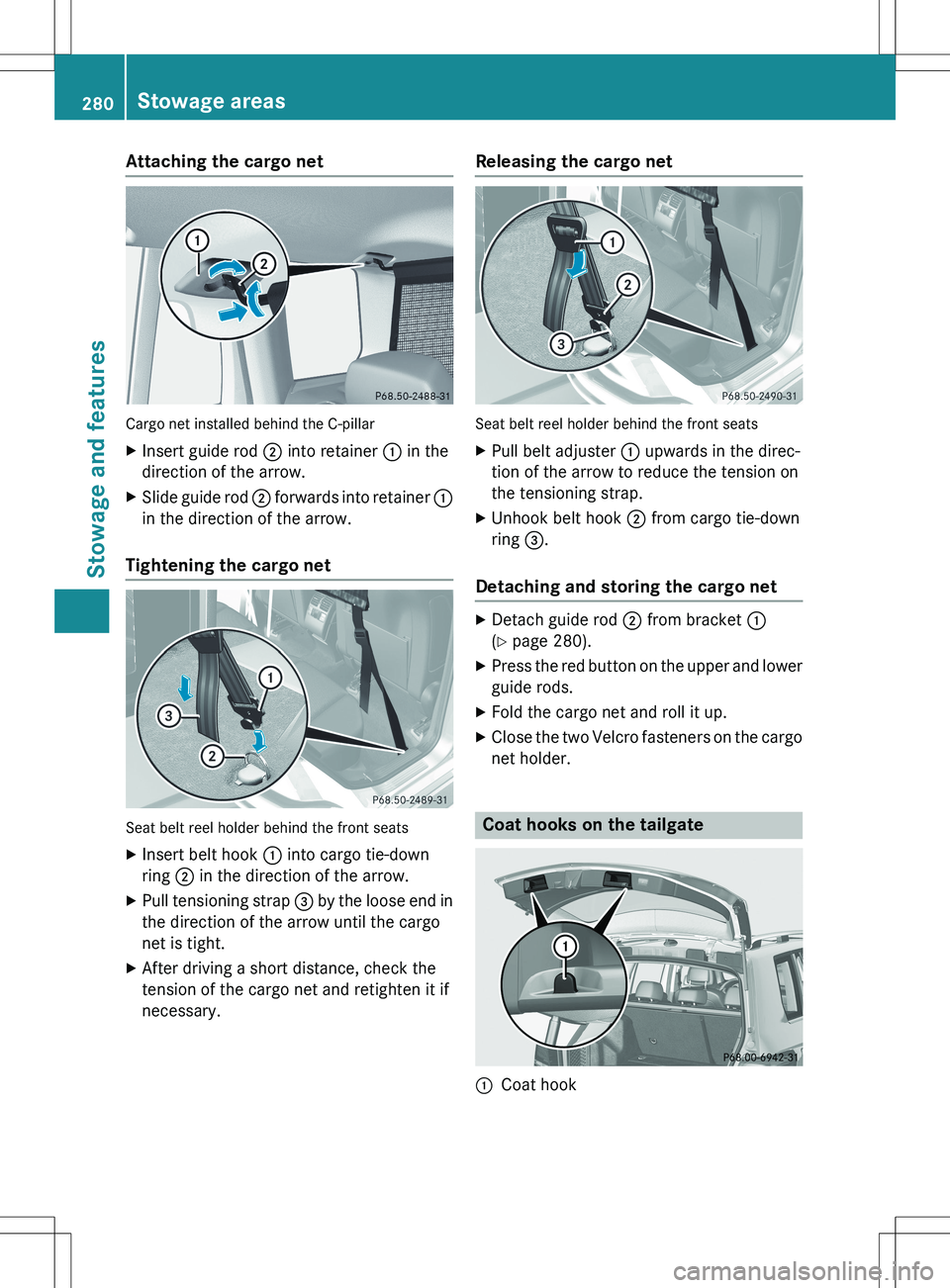
Cargo net installed behind the C-pillar
XInsert guide rod ; into retainer : in the
direction of the arrow.
X Slide guide rod ; forwards into retainer :
in the direction of the arrow.
Tightening the cargo net
Seat belt reel holder behind the front seats
X Insert belt hook : into cargo tie-down
ring ; in the direction of the arrow.
X Pull tensioning strap = by the loose end in
the direction of the arrow until the cargo
net is tight.
X After driving a short distance, check the
tension of the cargo net and retighten it if
necessary.
Releasing the cargo net
Seat belt reel holder behind the front seats
X Pull belt adjuster : upwards in the direc-
tion of the arrow to reduce the tension on
the tensioning strap.
X Unhook belt hook ; from cargo tie-down
ring =.
Detaching and storing the cargo net
X
Detach guide rod ; from bracket :
( Y page 280).
X Press the red button on the upper and lower
guide rods.
X Fold the cargo net and roll it up.
X Close the two Velcro fasteners on the cargo
net holder.
Coat hooks on the tailgate
:Coat hook
280Stowage areas
Stowage and features
Page 322 of 386
Always make sure that neither you nor the
battery is electrostatically charged. A build-
up of electrostatic charge can be caused, for
example:
R by wearing clothing made from synthetic
fibers
R due to friction between clothing and seats
R if you push or pull the battery across the
carpet or other synthetic materials
R if you wipe the battery with a cloth
GWARNING
Battery acid is caustic. There is a risk of injury.
Avoid contact with skin, eyes or clothing. Do
not inhale any battery gases. Do not lean over
the battery. Keep children away from batter-
ies. Wash away battery acid immediately with
plenty of clean water and seek medical atten-
tion.
GWARNING
During the charging process, a battery produ- ces hydrogen gas. If a short circuit occurs or
sparks are created, the hydrogen gas can
ignite. There is a risk of an explosion.
R Make sure that the positive terminal of a
connected battery does not come into con-
tact with vehicle parts.
R Never place metal objects or tools on a bat-
tery.
R It is important that you observe the descri-
bed order of the battery terminals when
connecting and disconnecting a battery.
R When jump-starting, make sure that the
battery poles with identical polarity are
connected.
R It is particularly important to observe the
described order when connecting and dis-
connecting the jumper cables.
R Never connect or disconnect the battery
terminals while the engine is running.
GWARNING
During charging and jump-starting, explosive
gases can escape from the battery. There is a
risk of an explosion.
Particularly avoid fire, open flames, creating
sparks and smoking. Ensure there is sufficient
ventilation while charging and jump-starting.
Do not lean over a battery.
HEnvironmental note
Batteries contain dangerous
substances. It is against the
law to dispose of them with
the household rubbish. They
must be collected separately and recycled to protect the
environment.
Dispose of batteries in an
environmentally friendly
manner. Take discharged
batteries to a qualified spe-
cialist workshop or a special
collection point for used bat-teries.
! Have the battery checked regularly at a
qualified specialist workshop.
Observe the service intervals in the Main-
tenance Booklet or contact a qualified spe-
cialist workshop for more information.
! You should have all work involving the
battery carried out at a qualified specialist
workshop. In the exceptional case that it is
necessary for you to disconnect the battery yourself, make sure that:
R you switch off the engine and remove the
SmartKey. On vehicles with KEYLESS-
GO, ensure that the ignition is switched
off. Check that all the indicator lamps in
the instrument cluster are off. Otherwise, electronic components, such as the
alternator, may be damaged.
R you first remove the negative terminal
clamp and then the positive terminal
clamp. Never swap the terminal clamps.
320Battery (vehicle)
Roadside Assistance
Page 339 of 386
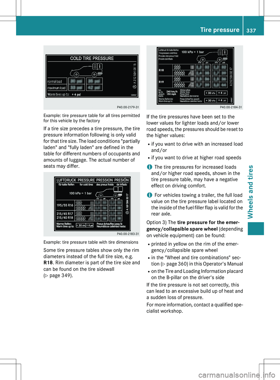
Example: tire pressure table for all tires permitted
for this vehicle by the factory
If a tire size precedes a tire pressure, the tirepressure information following is only valid
for that tire size. The load conditions "partially
laden" and "fully laden" are defined in the
table for different numbers of occupants and amounts of luggage. The actual number of
seats may differ.
Example: tire pressure table with tire dimensions
Some tire pressure tables show only the rim
diameters instead of the full tire size, e.g.
R18 . Rim diameter is part of the tire size and
can be found on the tire sidewall
( Y page 349).
If the tire pressures have been set to the
lower values for lighter loads and/or lower
road speeds, the pressures should be reset to
the higher values:
R if you want to drive with an increased load
and/or
R if you want to drive at higher road speeds
iThe tire pressures for increased loads
and/or higher road speeds, shown in the
tire pressure table, may have a negative
effect on driving comfort.
iFor vehicles towing a trailer, the full load
value on the tire pressure label located on
the inside of the fuel filler flap is valid for the rear axle.
Option 3) The tire pressure for the emer-
gency/collapsible spare wheel (depending
on vehicle equipment) can be found:
R printed in yellow on the rim of the emer-
gency/collapsible spare wheel
R in the "Wheel and tire combinations" sec-
tion ( Y page 360) in this Operator's Manual
R on the Tire and Loading Information placard
on the B-pillar on the driver's side
If the tire pressure is not set correctly, this
can lead to an excessive build up of heat and
a sudden loss of pressure.
For more information, contact a qualified spe- cialist workshop.
Tire pressure337
Wheels and tires
Z
Page 346 of 386
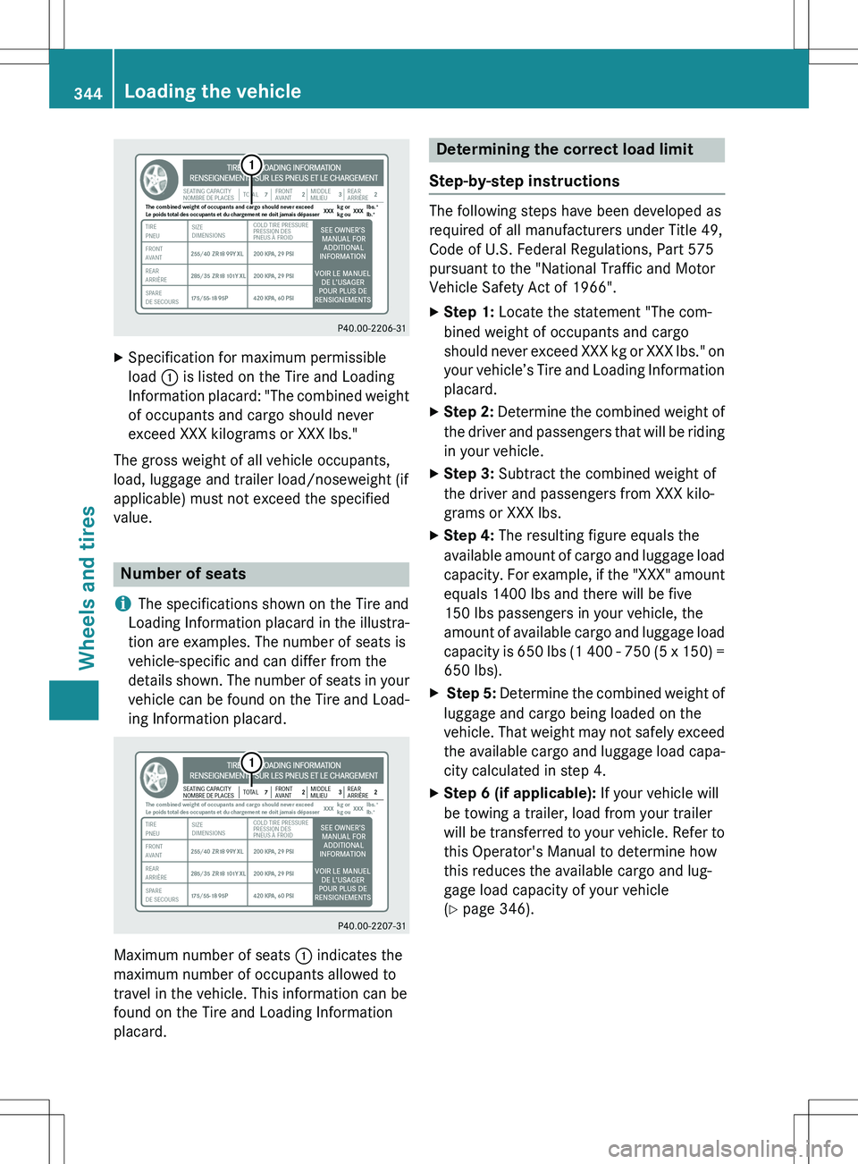
XSpecification for maximum permissible
load : is listed on the Tire and Loading
Information placard: "The combined weight of occupants and cargo should never
exceed XXX kilograms or XXX lbs."
The gross weight of all vehicle occupants,
load, luggage and trailer load/noseweight (if
applicable) must not exceed the specified
value.
Number of seats
iThe specifications shown on the Tire and
Loading Information placard in the illustra-
tion are examples. The number of seats is
vehicle-specific and can differ from the
details shown. The number of seats in your vehicle can be found on the Tire and Load-
ing Information placard.
Maximum number of seats : indicates the
maximum number of occupants allowed to
travel in the vehicle. This information can be
found on the Tire and Loading Information
placard.
Determining the correct load limit
Step-by-step instructions
The following steps have been developed as
required of all manufacturers under Title 49,
Code of U.S. Federal Regulations, Part 575
pursuant to the "National Traffic and Motor
Vehicle Safety Act of 1966". X Step 1: Locate the statement "The com-
bined weight of occupants and cargo
should never exceed XXX kg or XXX lbs." on your vehicle’s Tire and Loading Information
placard.
X Step 2: Determine the combined weight of
the driver and passengers that will be riding
in your vehicle.
X Step 3: Subtract the combined weight of
the driver and passengers from XXX kilo-
grams or XXX lbs.
X Step 4: The resulting figure equals the
available amount of cargo and luggage load
capacity. For example, if the "XXX" amount
equals 1400 lbs and there will be five
150 lbs passengers in your vehicle, the
amount of available cargo and luggage load
capacity is 650 lbs (1 400 - 750 (5 x 150) = 650 lbs).
X Step 5: Determine the combined weight of
luggage and cargo being loaded on the
vehicle. That weight may not safely exceed the available cargo and luggage load capa-
city calculated in step 4.
X Step 6 (if applicable): If your vehicle will
be towing a trailer, load from your trailer
will be transferred to your vehicle. Refer to
this Operator's Manual to determine how
this reduces the available cargo and lug-
gage load capacity of your vehicle
( Y page 346).
344Loading the vehicle
Wheels and tires
Page 357 of 386
Treadwear indicators
Narrow bars (tread wear bars) that are dis-
tributed over the tire tread. If the tire tread islevel with the bars, the wear limit of á in
(1.6 mm) has been reached.
Occupant distribution
The distribution of occupants in a vehicle at
their designated seating positions.
Total load limit
Nominal load and luggage load plus 68 kg
(150 lbs) multiplied by the number of seats in the vehicle.
Changing a wheel
Flat tire
You can find information on what to do in theevent of a flat tire in the "Flat tire" section
( Y page 314).
Information on driving with MOExtended tires
in the event of a flat tire can be found under
"MOExtended tires (tires with run-flat char-
acteristics" ( Y page 315).
Rotating the wheels
GWARNING
Interchanging the front and rear wheels may
severely impair the driving characteristics if
the wheels or tires have different dimensions.
The wheel brakes or suspension components
may also be damaged. There is a risk of acci-
dent.
Rotate front and rear wheels only if the wheels and tires are of the same dimensions.
! On vehicles equipped with a tire pressure
monitor, electronic components are loca-
ted in the wheel. Tire-mounting tools should not be used
near the valve. This could damage the elec-
tronic components.
Only have tires changed at a qualified spe-cialist workshop.
Always observe the instructions and safety
notes in the "Mounting a wheel" section
( Y page 356).
The wear patterns on the front and rear tires
differ, depending on the operating conditions.
Rotate the wheels before a clear wear pattern has formed on the tires. Front tires typically
wear more on the shoulders and the rear tires in the center.
If your vehicle's tire configuration allows, you can rotate the wheels according to the inter-
vals in the tire manufacturer's warranty book
in your vehicle documents. If no warranty
book is available, the tires should be rotated
every 3,000 to 6,000 miles (5,000 to
10,000 km), or earlier if tire wear requires. Do
not change the direction of wheel rotation.
Clean the contact surfaces of the wheel and
the brake disc thoroughly every time a wheel
is rotated. Check the tire pressure and reac-
tivate the tire pressure monitor if necessary.
Information on changing tires and mounting
the spare wheel ( Y page 355).
Direction of rotation
Tires with a specified direction of rotation
have additional benefits, e.g. if there is a risk
of hydroplaning. These advantages can only
be gained if the tires are installed correspond- ing to the direction of rotation.
An arrow on the sidewall of the tire indicates
its correct direction of rotation.
Storing wheels
Store wheels that are not being used in a cool,
dry and preferably dark place. Protect the
tires from oil, grease, gasoline and diesel.
Changing a wheel355
Wheels and tires
Z