2015 MERCEDES-BENZ GLE SUV check engine
[x] Cancel search: check enginePage 207 of 453
LIM indicator lamp
;on the cruise control lever
indicates which function you have selected:
R LIM indicator lamp ;
;off: cruise control is
selected
R LIM indicator lamp ;
; on: variable SPEED-
TRONIC is selected
When you activate cruise control, the stored
speed is shown in the multifunction display for
five seconds. In addition, the ésymbol
appears in the multifunction display.
Speedometer with segments: when cruise
control is activated, the segments from the
stored speed to the maximum permitted speed
light up.
Selecting cruise control X
Check whether LIM indicator lamp ;is off.
If it is off, cruise control is already selected.
If it is not, press the cruise control lever in the
direction of arrow A.
LIM indicator lamp ;in the cruise control
lever goes out. Cruise control is selected.
Activation conditions To activate cruise control, all of the following
activation conditions must be fulfilled:
R the electric parking brake must be released.
R you are driving faster than 30 km/h.
R ESP ®
must be switched on, but not interven-
ing.
R the transmission must be in position D.
R DSR must be deactivated.
R the Offroad Plus drive program must be deac-
tivated (vehicles with the Off-Road Engineer-
ing package).
R the cruise control function must be selected
(Y page 204).
Storing, maintaining and calling up a
speed Storing and maintaining the speed
X Accelerate the vehicle to the desired speed.
X Briefly press the cruise control lever up :or
down ?.
X Remove your foot from the accelerator pedal.
Cruise control is activated. The vehicle auto-
matically maintains the stored speed. i
Cruise control may be unable to maintain
the stored speed on uphill gradients. The
stored speed is resumed when the gradient
evens out. Cruise control maintains the
stored speed on downhill gradients by auto-
matically braking the vehicle.
Storing or calling up the speed G
WARNING
If you call up a stored speed and this is dif-
ferent from the current speed, the vehicle
accelerates or brakes. If you do not know
what the stored speed is, the vehicle may
accelerate or brake unexpectedly. There is a
risk of an accident.
Take the traffic conditions into account
before calling up the stored speed. If you do
not know what the stored speed is, store the
desired speed again.
X Briefly pull the cruise control lever towards
you =.
X Remove your foot from the accelerator pedal.
Cruise control is on and, when activated for
the first time, accepts the current speed or it
adjusts the vehicle's speed to the speed
stored.
Setting a speed Bear in mind that it may take a brief moment
until the vehicle has accelerated or braked to
the set speed.
X Press the cruise control lever up :for a
higher speed or down ?for a lower speed.
X Keep the cruise control lever pressed until the
desired speed is reached.
X Release the cruise control lever.
The new speed is stored.
X To adjust the set speed in 1 km/h incre-
ments:
briefly press the cruise control lever
up : or down ?to the pressure point.
The last stored speed increases or decreases
in 1 km/h increments.
X To adjust the set speed in 10 km/h incre-
ments: briefly press the cruise control lever
up : or down ?beyond the pressure point.
The last stored speed increases or decreases
in 10 km/h increments. 204
Driving systemsDriving and parking
Page 209 of 453
=
To activate at the current speed/last stored
speed
? To activate or reduce speed
A To switch between cruise control or
DISTRONIC PLUS and variable SPEED-
TRONIC
B To deactivate variable SPEEDTRONIC
With the cruise control lever, you can operate
cruise control or DISTRONIC PLUS and variable
SPEEDTRONIC.
LIM indicator lamp ;on the cruise control lever
indicates which function you have selected:
R LIM indicator lamp ;
; off: cruise control or
DISTRONIC PLUS is selected.
R LIM indicator lamp ; ;on: variable SPEED-
TRONIC is selected.
You can use the cruise control lever to limit the
speed to any speed above 30 km/h while the
engine is running.
Selecting SPEEDTRONIC
If there is a change of drivers, advise the new
driver of the limit speed stored. X Check whether LIM indicator lamp ;is on.
If it is on, variable SPEEDTRONIC is already
selected.
If it is not, press the cruise control lever in the direction of arrow A.
LIM indicator lamp ;in the cruise control
lever is on. Variable SPEEDTRONIC is selec-
ted.
Storing the current speed You can use the cruise control lever to limit the
speed to any speed above 30 km/h while the
engine is running.
X Briefly press the cruise control lever up :or
down ?tippen.
The current speed is stored and shown in the
multifunction display.
Speedometer with segments: the seg-
ments light up from the start of the scale up to
the stored speed limit.
The segments in the multifunction display
light up from the start of the scale up to the
stored speed. Storing the current speed or calling up the
last stored speed G
WARNING
If you call up the stored speed and it is lower
than the current speed, the vehicle deceler-
ates. If you do not know the stored speed, the vehicle could decelerate unexpectedly. There
is a risk of an accident.
Pay attention to the road and traffic condi-
tions before calling up the stored speed. If you do not know the stored speed, store the
desired speed again.
X Briefly pull the cruise control lever towards
you =.
Setting a speed
X To adjust the set speed in 10 km/h incre-
ments: briefly press the cruise control lever
up : beyond the pressure point for a higher
speed, or down ?for a lower speed.
or X Keep the cruise control lever pressed beyond
the pressure point until the desired speed is
set. Press the cruise control lever up :for a
higher speed or down ?for a lower speed.
X To adjust the set speed in 1 km/h incre-
ments:
briefly press the cruise control lever
up : to the pressure point for a higher speed
or down ?for a lower speed.
or X Keep the cruise control lever pressed to the
pressure point until the desired speed is set.
Press the cruise control lever up :for a
higher speed or down ?for a lower speed.
Switching SPEEDTRONIC to passive
If you depress the accelerator pedal beyond the pressure point (kickdown), SPEEDTRONIC is
switched to passive mode. The following mes-
sage appears in the multifunction display:
SPEEDTRONIC passive SPEEDTRONIC passive.
You can then exceed the stored speed. SPEED-
TRONIC is activated again if you:
R drive slower than the stored speed without
kickdown
R set a new speed or
R call up the last speed stored again 206
Driving systemsDriving and parking
Page 235 of 453
Cancelling Active Parking Assist
X
Stop the movement of the multifunction
steering wheel or steer yourself.
Active Parking Assist will be cancelled at
once. The Park Assist cancelled
Park Assist cancelled mes-
sage appears in the multifunction display.
or X Press the PARKTRONIC button (Y page 227).
PARKTRONIC is switched off and Active Park-
ing Assist is immediately cancelled. The
Park Assist cancelled Park Assist cancelled message appears
in the multifunction display.
Active Parking Assist is cancelled automatically if:
R the electric parking brake is applied
R transmission position Pis selected
R parking using Active Parking Assist is no lon-
ger possible
R you are driving faster than 10 km/h
R a wheel spins and ESP ®
intervenes or fails.
The ÷ warning lamp lights up in the instru-
ment cluster.
A warning tone sounds. The parking symbol dis-
appears and the multifunction display shows the
Park Assist cancelled
Park Assist cancelled message.
When Active Parking Assist is cancelled, you
must steer and brake again yourself.
If a system malfunction occurs, the vehicle is
braked to a standstill. To drive on, depress the
accelerator pedal again. Reversing camera
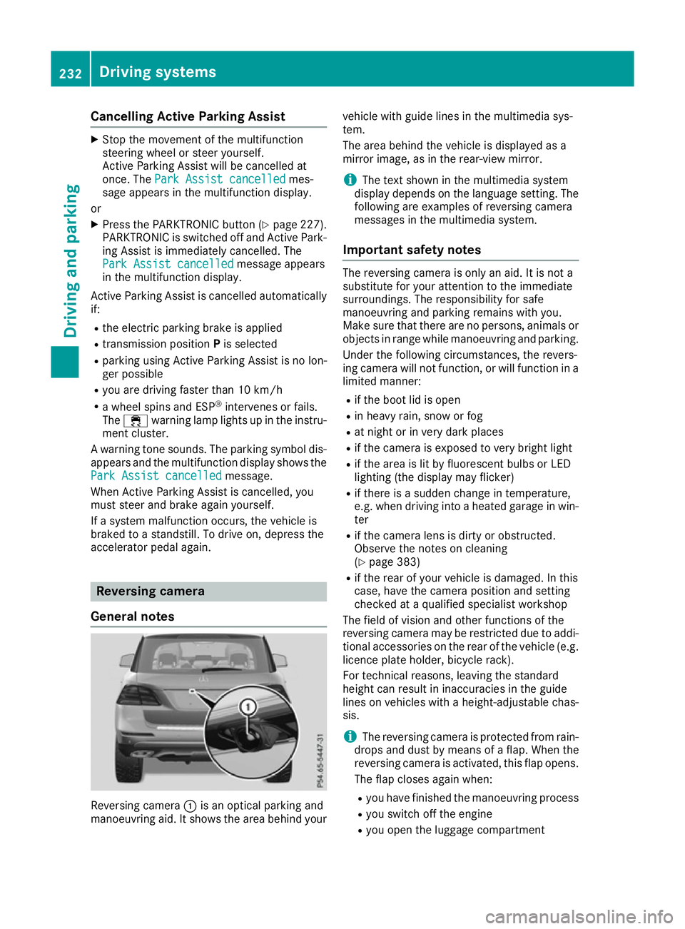
General notes Reversing camera
:is an optical parking and
manoeuvring aid. It shows the area behind your vehicle with guide lines in the multimedia sys-
tem.
The area behind the vehicle is displayed as a
mirror image, as in the rear-view mirror.
i The text shown in the multimedia system
display depends on the language setting. The
following are examples of reversing camera
messages in the multimedia system.
Important safety notes The reversing camera is only an aid. It is not a
substitute for your attention to the immediate
surroundings. The responsibility for safe
manoeuvring and parking remains with you.
Make sure that there are no persons, animals or
objects in range while manoeuvring and parking.
Under the following circumstances, the revers-
ing camera will not function, or will function in a limited manner:
R if the boot lid is open
R in heavy rain, snow or fog
R at night or in very dark places
R if the camera is exposed to very bright light
R if the area is lit by fluorescent bulbs or LED
lighting (the display may flicker)
R if there is a sudden change in temperature,
e.g. when driving into a heated garage in win-
ter
R if the camera lens is dirty or obstructed.
Observe the notes on cleaning
(Y page 383)
R if the rear of your vehicle is damaged. In this
case, have the camera position and setting
checked at a qualified specialist workshop
The field of vision and other functions of the
reversing camera may be restricted due to addi-
tional accessories on the rear of the vehicle (e.g. licence plate holder, bicycle rack).
For technical reasons, leaving the standard
height can result in inaccuracies in the guide
lines on vehicles with a height-adjustable chas-
sis.
i The reversing camera is protected from rain-
drops and dust by means of a flap. When the
reversing camera is activated, this flap opens.
The flap closes again when:
R you have finished the manoeuvring process
R you switch off the engine
R you open the luggage compartment 232
Driving systemsDriving and parking
Page 240 of 453
R
top view and image from the reversing cam-
era (130° viewing angle)
R top view and image from the front camera
(130° viewing angle without displaying the
maximum steering wheel angle)
R top view and enlarged rear view
R top view and enlarged front view
R top view and trailer view (vehicles with trailer
tow hitch)
R top view and rear-view images from the exte-
rior mirror cameras (rear wheel view)
R top view and forward-view images from the
exterior mirror cameras (front wheel view)
i The top view and trailer view are available
for vehicles equipped with a trailer tow hitch.
When the function is active and you shift the
transmission from Dor Rto N, the dynamic
guide lines are hidden.
When you change between transmission posi-
tions Dand R, you see the previously selected
front or rear view.
Distances measured by PARKTRONIC will also
be optically displayed:
R as red or yellow brackets around the vehicle
symbol in top view in split-screen mode or
R at the bottom right as red or yellow brackets
around the vehicle symbol in full-screen mode
The line thickness and colour of the brackets
show how far the vehicle is from an object.
R yellow brackets with thin lines: PARKTRONIC
is active
R yellow brackets with normal lines: an object is
present in close range of the vehicle
R red line: an object is present in the immediate
close range of the vehicle
i The camera in the rear area is protected
from raindrops and dust by means of a flap.
When the camera is activated, this flap opens.
The flap closes again when:
R you have finished the manoeuvring process
R you switch off the engine
R you open the luggage compartment
See the notes on cleaning (Y page 383).
For technical reasons, the flap may remain
open briefly after the camera has been deac-
tivated. Important safety notes The 360° camera is only an aid and may show a
distorted view of obstacles, show them incor-
rectly or not at all. The 360° camera is not a
substitute for attentive driving.
The responsibility for safe manoeuvring and
parking remains with you. Make sure that there
are no persons, animals or objects in range
while manoeuvring and parking.
You are always responsible for safety, and must always pay attention to your surroundings when
parking and manoeuvring. This applies to the
areas behind, in front of and beside the vehicle. You could otherwise endanger yourself and oth-
ers.
The 360° camera will not function or will func-
tion only in a limited manner:
R if the doors are open
R if the exterior mirrors are folded in
R if the tailgate is open
R in heavy rain, snow or fog
R at night or in very dark places
R if the cameras are exposed to very bright light
R if the area is lit by fluorescent bulbs or LED
lighting (the display may flicker)
R if there is a sudden change in temperature,
e.g. when driving into a heated garage in win-
ter
R if the camera lenses are dirty or covered
R if the vehicle components in which the cam-
eras are fitted are damaged. In this event,
have the camera position and setting checked
at a qualified specialist workshop.
Do not use the 360° camera under such cir-
cumstances. You could otherwise injure others
or damage objects when parking the vehicle.
Guide lines are always shown at road level. In
trailer mode, the guide lines are shown at the
level of the trailer coupling.
The field of vision and other functions of the
camera system may be restricted due to addi-
tional accessories on the rear of the vehicle (e.g.
licence plate holder, bicycle rack).
On vehicles with height-adjustable suspension,
due to the technical conditions, leaving the
standard height can result in:
R inaccuracies in the guide lines
R inaccuracies in the display of generated
images (top view) Driving systems
237Driving and parking Z
Page 249 of 453
ted by the flashing of red warning lamp
:.
There are no further warning tones.
Activating Blind Spot Assist X Make sure that Blind Spot Assist is activated
in the on-board computer (Y page 291).
X Turn the key to position 2in the ignition lock.
Warning lamps :in the exterior mirrors light
up red for approximately 1.5 second s and
then turn yellow.
Towing a trailer
If you couple up a trailer, make sure that you
have correctly established the electrical con-
nection. This can be accomplished by checking
the trailer lighting. Blind Spot Assist is then
deactivated. The indicator lamp lights up yellow
in the exterior mirrors and the Blind Spot Blind Spot
Assist not available when towing a
Assist not available when towing a
trailer See Owner's Manual
trailer See Owner's Manual message
appears in the multifunction display.
i You can deactivate the indicator lamps in
the exterior mirrors.
To do so, you will need to deactivate Blind
Spot Assist if:
R the key is in position 2in the ignition lock
R the engine is not running
Lane Keeping Assist General notes
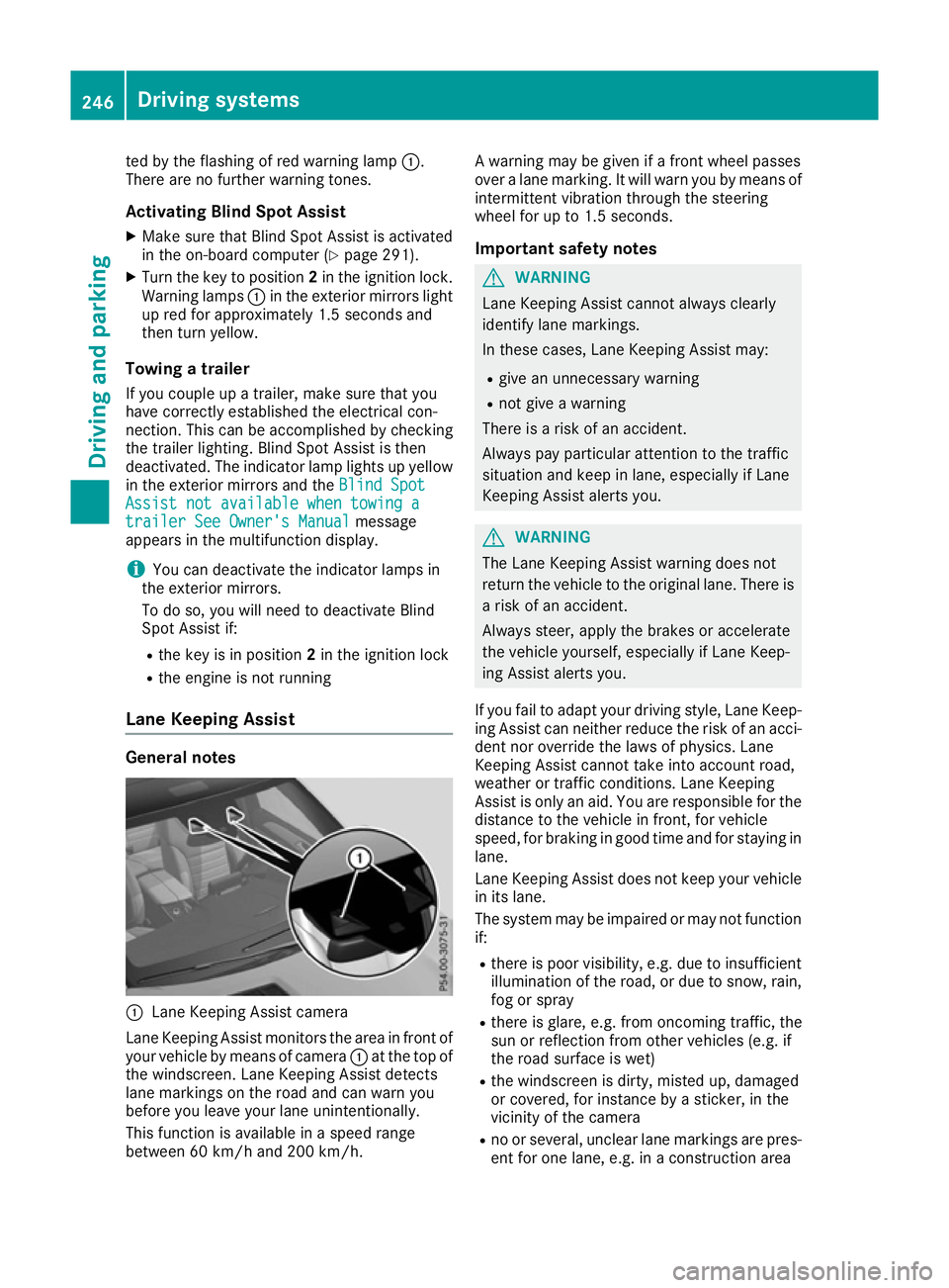
:
Lane Keeping Assist camera
Lane Keeping Assist monitors the area in front of
your vehicle by means of camera :at the top of
the windscreen. Lane Keeping Assist detects
lane markings on the road and can warn you
before you leave your lane unintentionally.
This function is available in a speed range
between 60 km/h and 200 km/h. A warning may be given if a front wheel passes
over a lane marking. It will warn you by means of
intermittent vibration through the steering
wheel for up to 1.5 second s.
Im portant safety notes G
WARNING
Lane Keeping Assist cannot always clearly
identify lane markings.
In these cases, Lane Keeping Assist may:
R give an unnecessary warning
R not give a warning
There is a risk of an accident.
Always pay particular attention to the traffic
situation and keep in lane, especially if Lane
Keeping Assist alerts you. G
WARNING
The Lane Keeping Assist warning does not
return the vehicle to the original lane. There is a risk of an accident.
Always steer, apply the brakes or accelerate
the vehicle yourself, especially if Lane Keep-
ing Assist alerts you.
If you fail to adapt your driving style, Lane Keep-
ing Assist can neither reduce the risk of an acci-
dent nor override the laws of physics. Lane
Keeping Assist cannot take into account road,
weather or traffic conditions. Lane Keeping
Assist is only an aid. You are responsible for the distance to the vehicle in front, for vehicle
speed, for braking in good time and for staying in
lane.
Lane Keeping Assist does not keep your vehicle
in its lane.
The system may be impaired or may not function if:
R there is poor visibility, e.g. due to insufficient
illumination of the road, or due to snow, rain,fog or spray
R there is glare, e.g. from oncoming traffic, the
sun or reflection from other vehicles (e.g. if
the road surface is wet)
R the windscreen is dirty, misted up, damaged
or covered, for instance by a sticker, in the
vicinity of the camera
R no or several, unclear lane markings are pres-
ent for one lane, e.g. in a construction area 246
Driving systemsDriving and parking
Page 252 of 453
vehicle with a difference in speed of less than
12 km/h, a delayed warning occurs.
The yellow indicator lamp goes out if reverse
gear is engaged. Active Blind Spot Assist is not
operational.
The brightness of the indicator/warning lamps
is adjusted automatically according to the
brightness of the surroundings.
Visual and acoustic collision warning
If you switch on the turn signals to change lanes
and a vehicle is detected in the side monitoring range, you receive a visual and acoustic collision
warning. You then hear a double warning tone
and red warning lamp :flashes. If the turn sig-
nal remains on, detected vehicles are indicated
by the flashing of red warning lamp :. There are
no further warning tones.
Course-correcting brake application If Active Blind Spot Assist detects a risk of a side
impact in the monitoring range, a course-cor-
recting brake application is carried out. This is
designed to help you avoid a collision. G
WARNING
A course-correcting brake application cannot always prevent a collision. There is a risk of an
accident.
Always steer, brake or accelerate yourself,
especially if Active Blind Spot Assist warns
you or makes a course-correcting brake appli-
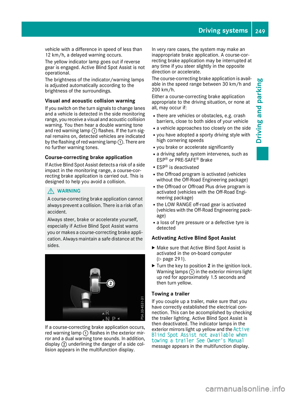
cation. Always maintain a safe distance at the sides. If a course-correcting brake application occurs,
red warning lamp :flashes in the exterior mir-
ror and a dual warning tone sounds. In addition, display ;underlining the danger of a side col-
lision appears in the multifunction display. In very rare cases, the system may make an
inappropriate brake application. A course-cor-
recting brake application may be interrupted at
any time if you steer slightly in the opposite
direction or accelerate.
The course-correcting brake application is avail-
able in the speed range between 30 km/h and
200 km/h.
Either a course-correcting brake application
appropriate to the driving situation, or none at
all, may occur if:
R there are vehicles or obstacles, e.g. crash
barriers, close to both sides of your vehicle
R a vehicle approaches too closely on the side
R you have adopted a sporty driving style with
high cornering speeds
R you brake or accelerate significantly
R a driving safety system intervenes, such as
ESP ®
or PRE-SAFE ®
Brake
R ESP ®
is deactivated
R the Offroad program is activated (vehicles
without the Off-Road Engineering package)
R the Offroad or Offroad Plus drive program is
activated (vehicles with the Off-Road Engi-
neering package)
R the LOW RANGE off-road gear is activated
(vehicles with the Off-Road Engineering pack-
age)
R a loss of tyre pressure or a defective tyre is
detected
Activating Active Blind Spot Assist
X Make sure that Active Blind Spot Assist is
activated in the on-board computer
(Y page 291).
X Turn the key to position 2in the ignition lock.
Warning lamps :in the exterior mirrors light
up red for approximately 1.5 seconds and
then turn yellow.
Towing a trailer
If you couple up a trailer, make sure that you
have correctly established the electrical con-
nection. This can be accomplished by checking
the trailer lighting. Active Blind Spot Assist is
then deactivated. The indicator lamps in the
exterior mirrors light up yellow and the Active Active
Blind Spot Assist not available when
Blind Spot Assist not available when
towing a trailer See Owner's Manual towing a trailer See Owner's Manual
message appears in the multifunction display. Driving systems
249Driving and parking Z
Page 278 of 453
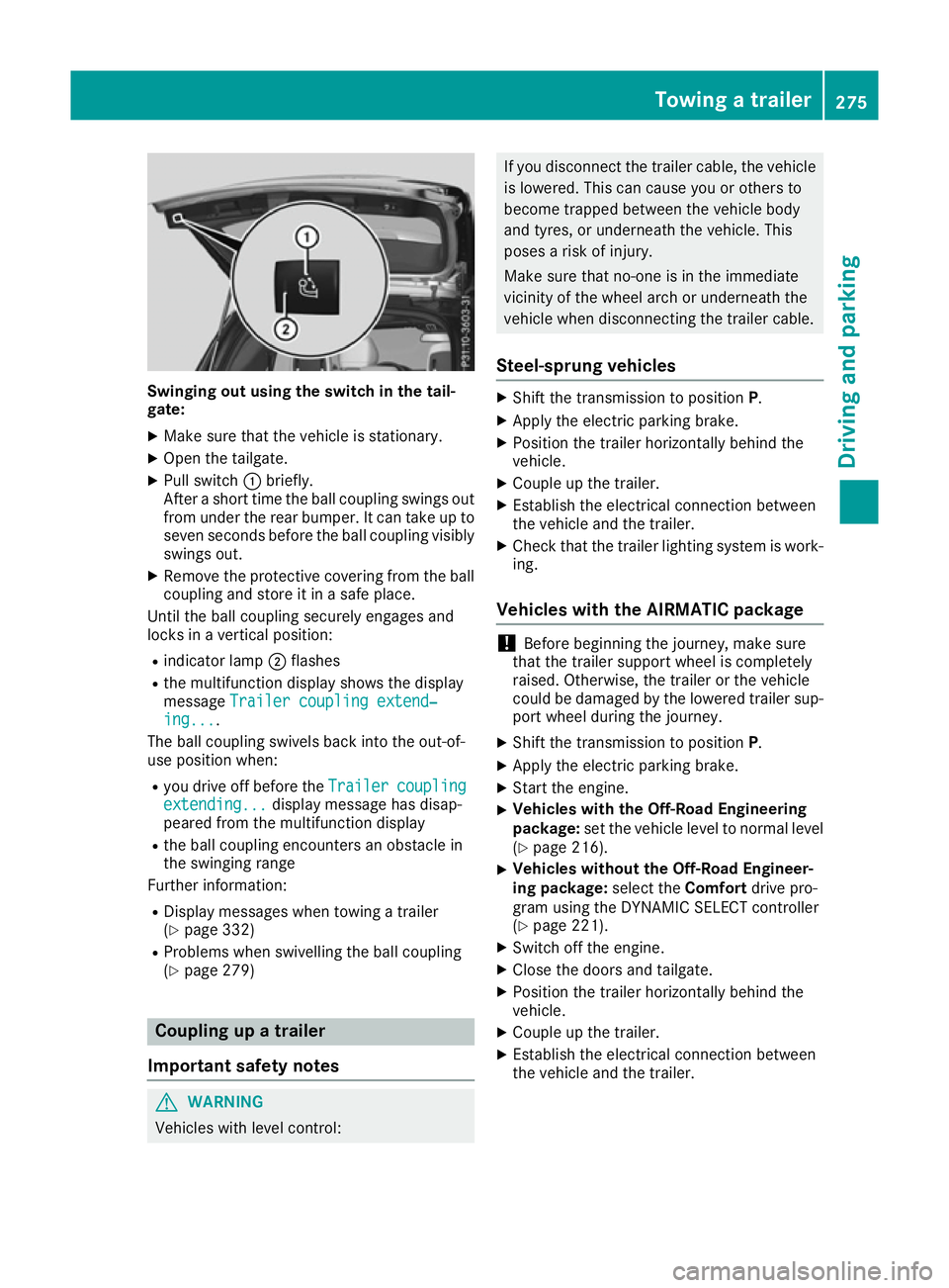
Swinging out using the switch in the tail-
gate:
X Make sure that the vehicle is stationary.
X Open the tailgate.
X Pull switch :briefly.
After a short time the ball coupling swings out from under the rear bumper. It can take up to
seven seconds before the ball coupling visibly
swings out.
X Remove the protective covering from the ball
coupling and store it in a safe place.
Until the ball coupling securely engages and
locks in a vertical position:
R indicator lamp ;flashes
R the multifunction display shows the display
message Trailer coupling extend‐ Trailer coupling extend‐
ing...
ing....
The ball coupling swivels back into the out-of-
use position when:
R you drive off before the Trailer Trailercoupling
coupling
extending...
extending... display message has disap-
peared from the multifunction display
R the ball coupling encounters an obstacle in
the swinging range
Further information:
R Display messages when towing a trailer
(Y page 332)
R Problems when swivelling the ball coupling
(Y page 279) Coupling up a trailer
Important safety notes G
WARNING
Vehicles with level control: If you disconnect the trailer cable, the vehicle
is lowered. This can cause you or others to
become trapped between the vehicle body
and tyres, or underneath the vehicle. This
poses a risk of injury.
Make sure that no-one is in the immediate
vicinity of the wheel arch or underneath the
vehicle when disconnecting the trailer cable.
Steel-sprung vehicles X
Shift the transmission to position P.
X Apply the electric parking brake.
X Position the trailer horizontally behind the
vehicle.
X Couple up the trailer.
X Establish the electrical connection between
the vehicle and the trailer.
X Check that the trailer lighting system is work-
ing.
Vehicles with the AIRMATIC package !
Before beginning the journey, make sure
that the trailer support wheel is completely
raised. Otherwise, the trailer or the vehicle
could be damaged by the lowered trailer sup- port wheel during the journey.
X Shift the transmission to position P.
X Apply the electric parking brake.
X Start the engine.
X Vehicles with the Off-Road Engineering
package:
set the vehicle level to normal level
(Y page 216).
X Vehicles without the Off-Road Engineer-
ing package:
select theComfortdrive pro-
gram using the DYNAMIC SELECT controller
(Y page 221).
X Switch off the engine.
X Close the doors and tailgate.
X Position the trailer horizontally behind the
vehicle.
X Couple up the trailer.
X Establish the electrical connection between
the vehicle and the trailer. Towing a trailer
275Driving and parking Z
Page 279 of 453
X
Check that the trailer lighting system is work-
ing.
X Push the combination switch upwards and
downwards and check whether the corre-
sponding turn signal on the trailer is flashing.
A connected trailer is only detected when the
electrical connection is established correctly
and when the lighting system is working prop-
erly. The function of other systems also depends on this, for example:
R ESP ®
R PARKTRONIC
R Active Parking Assist
R Active Blind Spot Assist
R Active Lane Keeping Assist
i Vehicles with the AIRMATIC package:
if
you couple up a trailer, the vehicle initially
remains at the selected level of the drive pro- gram set. Observe the following when cou-
pling up a trailer:
R If the normal level was not selected previ-
ously, the vehicle automatically adopts the
normal level starting from a speed of
30 km/h. Even at higher speeds, it does not drop below the normal level.
R Vehicle levels below the normal level are
not available.
R The raised level is available up to a speed of
30 km/h.
R This also applies when using accessories
that are plugged into the socket of the
trailer tow hitch (e.g. a bicycle rack).
R Before driving with a trailer, please observe
the information on the trailer support
wheel. Uncoupling a trailer
Important safety notes G
WARNING
If you uncouple a trailer with an engaged over- run brake, you could trap your hand between
the vehicle and the trailer drawbar. This poses a risk of injury.
Do not uncouple a trailer with an engaged
overrun brake. G
WARNING
Vehicles with level control:
If you disconnect the trailer cable, the vehicle is lowered. This can cause you or others to
become trapped between the vehicle body
and tyres, or underneath the vehicle. This
poses a risk of injury.
Make sure that no-one is in the immediate
vicinity of the wheel arch or underneath the
vehicle when disconnecting the trailer cable.
! Do not disconnect a trailer with an engaged
overrun brake. Otherwise, your vehicle could
be damaged by the rebounding of the overrun
brake.
! Remove the adapter cable before folding in
the ball coupling. You could otherwise dam-
age the rear bumper and the adapter cable.
Steel-sprung vehicles X
Shift the transmission to position P.
X Apply the electric parking brake.
X Secure the trailer against rolling away.
X Remove the trailer cable and decouple the
trailer.
Vehicles with the AIRMATIC package X
Shift the transmission to position P.
X Apply the electric parking brake.
X Start the engine.
X Close the doors and tailgate.
X Secure the trailer against rolling away.
X Remove the trailer cable and decouple the
trailer.
X Switch off the engine. Swinging the ball coupling in
! Do not attempt to speed the up the swing-
out procedure by applying additional pressure
with your foot. The system could otherwise be
mechanically damaged. 276
Towing a trailerDriving and parking