2015 MERCEDES-BENZ GLE SUV light
[x] Cancel search: lightPage 176 of 453
or
X Use the DYNAMIC SELECT controller to
change the drive program.
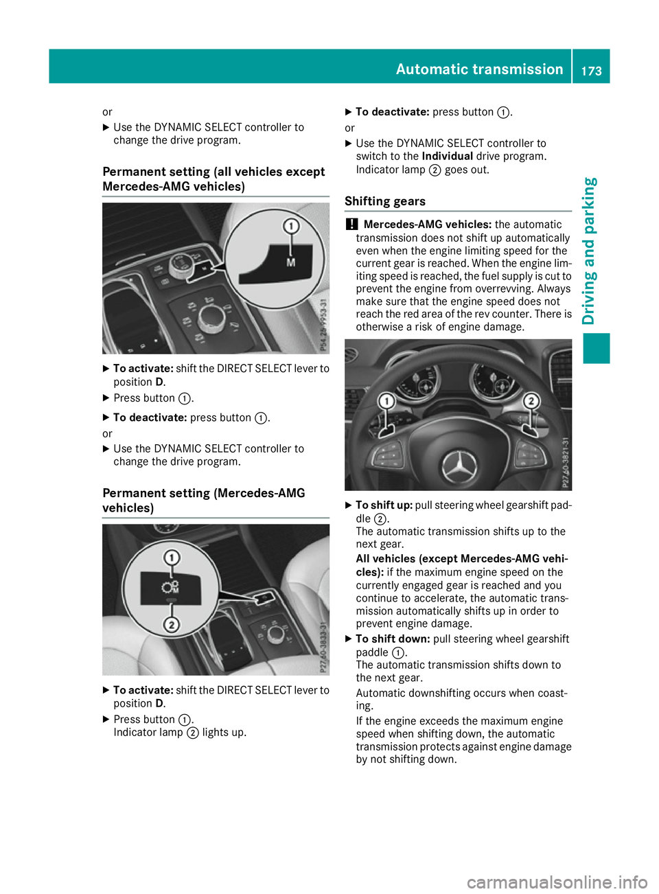
Permanent setting (all vehicles except
Mercedes-AMG vehicles) X
To activate: shift the DIRECT SELECT lever to
position D.
X Press button :.
X To deactivate: press button:.
or X Use the DYNAMIC SELECT controller to
change the drive program.
Permanent setting (Mercedes-AMG
vehicles) X
To activate: shift the DIRECT SELECT lever to
position D.
X Press button :.
Indicator lamp ;lights up. X
To deactivate: press button:.
or
X Use the DYNAMIC SELECT controller to
switch to the Individualdrive program.
Indicator lamp ;goes out.
Shifting gears !
Mercedes-AMG vehicles:
the automatic
transmission does not shift up automatically
even when the engine limiting speed for the
current gear is reached. When the engine lim- iting speed is reached, the fuel supply is cut to
prevent the engine from overrevving. Always
make sure that the engine speed does not
reach the red area of the rev counter. There is
otherwise a risk of engine damage. X
To shift up: pull steering wheel gearshift pad-
dle ;.
The automatic transmission shifts up to the
next gear.
All vehicles (except Mercedes-AMG vehi-
cles): if the maximum engine speed on the
currently engaged gear is reached and you
continue to accelerate, the automatic trans-
mission automatically shifts up in order to
prevent engine damage.
X To shift down: pull steering wheel gearshift
paddle :.
The automatic transmission shifts down to
the next gear.
Automatic downshifting occurs when coast-
ing.
If the engine exceeds the maximum engine
speed when shifting down, the automatic
transmission protects against engine damage
by not shifting down. Automatic transmission
173Driving and parking Z
Page 180 of 453
Opening the fuel filler flap (except
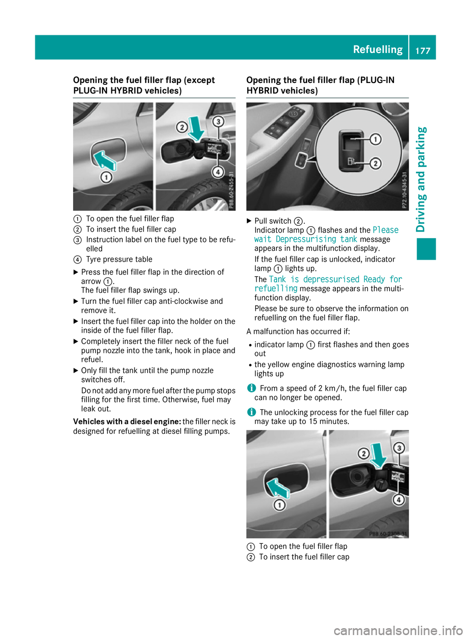
PLUG-IN HYBRID vehicles)
:
To open the fuel filler flap
; To insert the fuel filler cap
= Instruction label on the fuel type to be refu-
elled
? Tyre pressure table
X Press the fuel filler flap in the direction of
arrow :.
The fuel filler flap swings up.
X Turn the fuel filler cap anti-clockwise and
remove it.
X Insert the fuel filler cap into the holder on the
inside of the fuel filler flap.
X Completely insert the filler neck of the fuel
pump nozzle into the tank, hook in place and
refuel.
X Only fill the tank until the pump nozzle
switches off.
Do not add any more fuel after the pump stops filling for the first time. Otherwise, fuel may
leak out.
Vehicles with a diesel engine: the filler neck is
designed for refuelling at diesel filling pumps. Opening the fuel filler flap (PLUG-IN
HYBRID vehicles) X
Pull switch ;.
Indicator lamp :flashes and the Please Please
wait Depressurising tank
wait Depressurising tank message
appears in the multifunction display.
If the fuel filler cap is unlocked, indicator
lamp :lights up.
The Tank is depressurised Ready for Tank is depressurised Ready for
refuelling
refuelling message appears in the multi-
function display.
Please be sure to observe the information on refuelling on the fuel filler flap.
A malfunction has occurred if:
R indicator lamp :first flashes and then goes
out
R the yellow engine diagnostics warning lamp
lights up
i From a speed of 2 km/h, the fuel filler cap
can no longer be opened.
i The unlocking process for the fuel filler cap
may take up to 15 minutes. :
To open the fuel filler flap
; To insert the fuel filler cap Refuelling
177Driving and parking Z
Page 189 of 453
When displays
:and ;on the charging cable
light up, this means the following: Display
:
: Lights up
green The on-board voltage is con-
nected. The high-voltage bat-
tery can be charged.
Flashes red The power supply from the
building is faulty.
Display
; ; Lights up
green There are no faults. The high-
voltage battery can be
charged.
Lights up red The protective and indicator
system has detected a fault
due to an internal malfunc-
tion. The high-voltage battery
cannot be charged. If the control detects residual current or a mal-
function, the charging process is halted. Once
the malfunction has been rectified the charging process is resumed automatically.
Information on problems relating to the charg-
ing process (Y page 190).
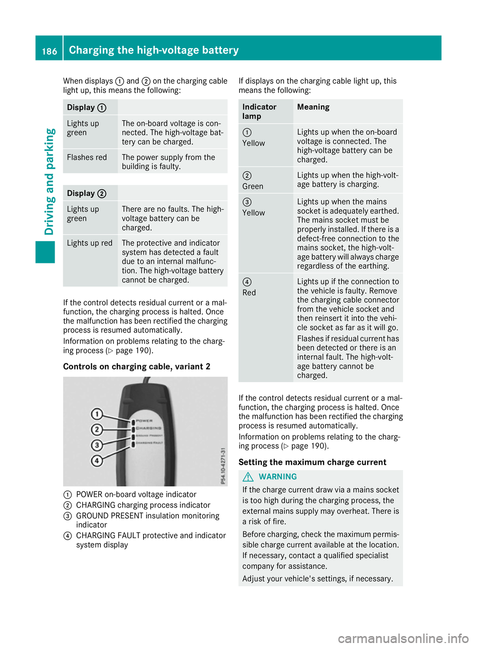
Controls on charging cable, variant 2 :
POWER on-board voltage indicator
; CHARGING charging process indicator
= GROUND PRESENT insulation monitoring
indicator
? CHARGING FAULT protective and indicator
system display If displays on the charging cable light up, this
means the following: Indicator
lamp Meaning
:
Yellow
Lights up when the on-board
voltage is connected. The
high-voltage battery can be
charged.
;
Green
Lights up when the high-volt-
age battery is charging.
=
Yellow
Lights up when the mains
socket is adequately earthed.
The mains socket must be
properly installed. If there is a defect-free connection to the
mains socket, the high-volt-
age battery will always charge
regardless of the earthing. ?
Red
Lights up if the connection to
the vehicle is faulty. Remove
the charging cable connector
from the vehicle socket and
then reinsert it into the vehi-
cle socket as far as it will go.
Flashes if residual current has been detected or there is an
internal fault. The high-volt-
age battery cannot be
charged. If the control detects residual current or a mal-
function, the charging process is halted. Once
the malfunction has been rectified the charging process is resumed automatically.
Information on problems relating to the charg-
ing process (Y page 190).
Setting the maximum charge current G
WARNING
If the charge current draw via a mains socket is too high during the charging process, the
external mains supply may overheat. There isa risk of fire.
Before charging, check the maximum permis-
sible charge current available at the location.
If necessary, contact a qualified specialist
company for assistance.
Adjust your vehicle's settings, if necessary. 186
Charging the high-voltage batteryDriving and parking
Page 190 of 453
!
If the charge current is too high, the fuse
could be tripped or the external mains supply could overheat. Check if the external mains
supply is equipped to handle the programmed charge current. If necessary, reduce the pro-
grammed charge current or use a different
mains socket.
Before starting the charging process at a power
socket, check the maximum permissible charge current for the relevant power socket or the
building.
You can set the maximum permissible charge
current
R on the charging cable controls (only charging
cable variant 1)
R in the Settings Settings menu of the on-board com-
puter (Y page 292).
The lower value of the two charge current set-
tings – on the charge cable controls and in the
on-board computer – determines the maximum
charge current. If you cannot set the precise
maximum permitted charge current, select the
next lowest available value.
Only set the maximum permitted charge current
in the on-board computer menu if:
R it is not possible to set the charge current on
the charging cable
R the precise maximum permitted charge cur-
rent can only be set via the on-board com-
puter.
Setting the maximum permitted charge current on the charging cable of variant 1 is described
below.
X To adjust the setting: press button?
repeatedly until the desired setting is selec-
ted in display =.
R Two LEDs are flashing: minimum setting
R All LEDs are flashing: maximum setting
If, after the charging process, the charging cable is:
R left connected to the power socket, the cur-
rently selected values will be used for the next
charging process.
R removed from the power socket, the values
will be reset to the minimum setting for the
next charging process. You may then need to
reset the values of the maximum charge cur-
rent.
i If the vehicle requires more time than usual
when charging, check the maximum charge current settings using the controls on the
charging cable or in the on-board computer's
menu.
Indicator lamps on the vehicle socket
When the indicator lamps on the vehicle socket
light up, this means the following: Left indica-
tor lamp
Ì Ì
Lights up
white The vehicle socket is
released. The charging cable
can be removed or connec-
ted.
Flashes white The charging cable connector
is not correctly inserted and
cannot be locked. Remove
the charging cable connector
from the vehicle socket and
then reinsert it into the vehi-
cle socket as far as it will go. Right indica-
tor lamp
Ý Ý
Flashes
orange The connection between the
vehicle and the current
source is being established
before charging begins.
Flashes
green The high-voltage battery is
charging.
Flashes red A malfunction has occurred
while charging.
The indicator lamp goes out
after approximately
90 seconds.
Lights up
orange Charging of the high-voltage
battery has been temporarily
interrupted.
The indicator lamp goes out
after approximately
90 seconds.
Lights up
green The high-voltage battery is
fully charged.
The indicator lamp goes out
after approximately
90 seconds.Charging the high-voltage battery
187Driving and parking Z
Page 191 of 453
i
If the indicator lamps are off, lock or unlock
the vehicle. The indicator lamps will then dis- play the current status of the charging proc-
ess again.
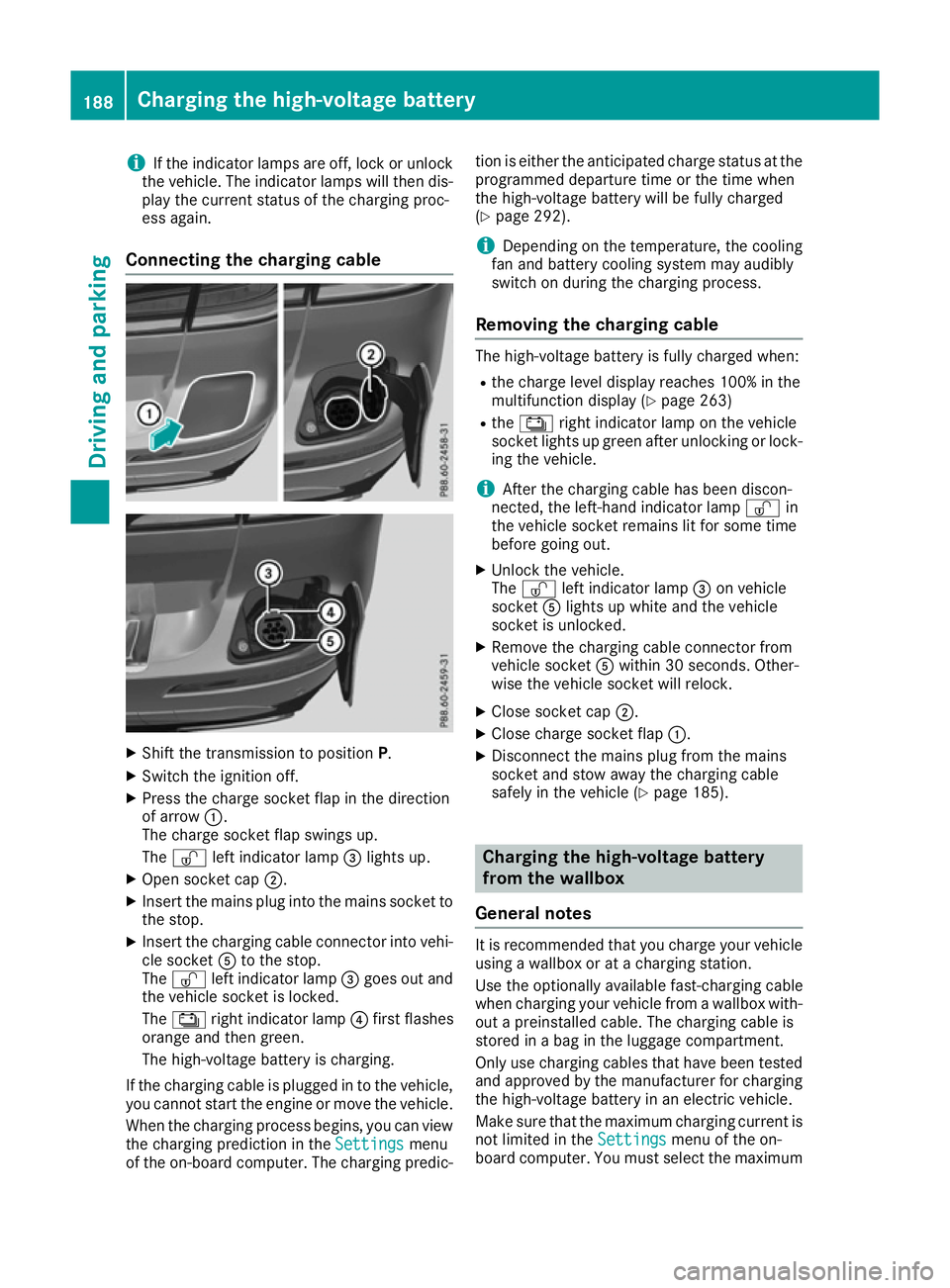
Connecting the charging cable X
Shift the transmission to position P.
X Switch the ignition off.
X Press the charge socket flap in the direction
of arrow :.
The charge socket flap swings up.
The Ì left indicator lamp =lights up.
X Open socket cap ;.
X Insert the mains plug into the mains socket to
the stop.
X Insert the charging cable connector into vehi-
cle socket Ato the stop.
The Ì left indicator lamp =goes out and
the vehicle socket is locked.
The Ý right indicator lamp ?first flashes
orange and then green.
The high-voltage battery is charging.
If the charging cable is plugged in to the vehicle,
you cannot start the engine or move the vehicle.
When the charging process begins, you can viewthe charging prediction in the Settings
Settings menu
of the on-board computer. The charging predic- tion is either the anticipated charge status at the
programmed departure time or the time when
the high-voltage battery will be fully charged
(Y page 292).
i Depending on the temperature, the cooling
fan and battery cooling system may audibly
switch on during the charging process.
Removing the charging cable The high-voltage battery is fully charged when:
R
the charge level display reaches 100% in the
multifunction display (Y page 263)
R the Ý right indicator lamp on the vehicle
socket lights up green after unlocking or lock-
ing the vehicle.
i After the charging cable has been discon-
nected, the left-hand indicator lamp Ìin
the vehicle socket remains lit for some time
before going out.
X Unlock the vehicle.
The Ì left indicator lamp =on vehicle
socket Alights up white and the vehicle
socket is unlocked.
X Remove the charging cable connector from
vehicle socket Awithin 30 seconds. Other-
wise the vehicle socket will relock.
X Close socket cap ;.
X Close charge socket flap :.
X Disconnect the mains plug from the mains
socket and stow away the charging cable
safely in the vehicle (Y page 185). Charging the high-voltage battery
from the wallbox
General notes It is recommended that you charge your vehicle
using a wallbox or at a charging station.
Use the optionally available fast-charging cable
when charging your vehicle from a wallbox with- out a preinstalled cable. The charging cable is
stored in a bag in the luggage compartment.
Only use charging cables that have been tested
and approved by the manufacturer for charging
the high-voltage battery in an electric vehicle.
Make sure that the maximum charging current is
not limited in the Settings Settingsmenu of the on-
board computer. You must select the maximum 188
Charging the high-voltage batteryDriving and parking
Page 192 of 453
value if charging at a wallbox or a charging sta-
tion (Y page 292).
Observe the "Important safety notes"
(Y page 182).
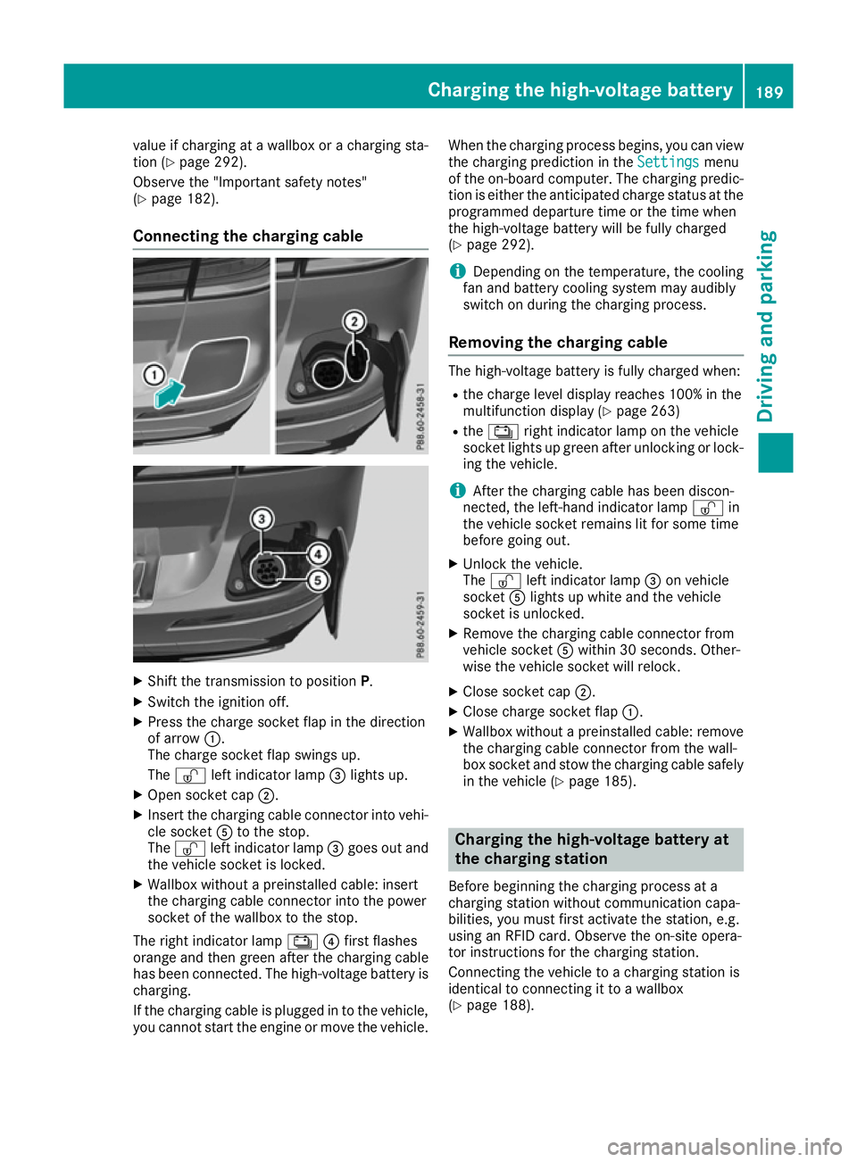
Connecting the charging cable X
Shift the transmission to position P.
X Switch the ignition off.
X Press the charge socket flap in the direction
of arrow :.
The charge socket flap swings up.
The Ì left indicator lamp =lights up.
X Open socket cap ;.
X Insert the charging cable connector into vehi-
cle socket Ato the stop.
The Ì left indicator lamp =goes out and
the vehicle socket is locked.
X Wallbox without a preinstalled cable: insert
the charging cable connector into the power
socket of the wallbox to the stop.
The right indicator lamp Ý?first flashes
orange and then green after the charging cable
has been connected. The high-voltage battery is charging.
If the charging cable is plugged in to the vehicle,
you cannot start the engine or move the vehicle. When the charging process begins, you can view
the charging prediction in the Settings
Settings menu
of the on-board computer. The charging predic-
tion is either the anticipated charge status at the
programmed departure time or the time when
the high-voltage battery will be fully charged
(Y page 292).
i Depending on the temperature, the cooling
fan and battery cooling system may audibly
switch on during the charging process.
Removing the charging cable The high-voltage battery is fully charged when:
R
the charge level display reaches 100% in the
multifunction display (Y page 263)
R the Ý right indicator lamp on the vehicle
socket lights up green after unlocking or lock-
ing the vehicle.
i After the charging cable has been discon-
nected, the left-hand indicator lamp Ìin
the vehicle socket remains lit for some time
before going out.
X Unlock the vehicle.
The Ì left indicator lamp =on vehicle
socket Alights up white and the vehicle
socket is unlocked.
X Remove the charging cable connector from
vehicle socket Awithin 30 seconds. Other-
wise the vehicle socket will relock.
X Close socket cap ;.
X Close charge socket flap :.
X Wallbox without a preinstalled cable: remove
the charging cable connector from the wall-
box socket and stow the charging cable safely in the vehicle (Y page 185). Charging the high-voltage battery at
the charging station
Before beginning the charging process at a
charging station without communication capa-
bilities, you must first activate the station, e.g.
using an RFID card. Observe the on-site opera-
tor instructions for the charging station.
Connecting the vehicle to a charging station is
identical to connecting it to a wallbox
(Y page 188). Charging the high-voltage battery
189Driving and parking Z
Page 194 of 453
Problem
Possible causes/consequences and
M
MSolutions The charging cable con-
nector cannot be
removed from the vehi-
cle socket. The charging cable connector has not been unlocked.
X Press the %button on the key.
The Ì indicator lamp on the vehicle socket lights up. The charg-
ing cable connector is unlocked.
X Remove the charging cable connector from the vehicle socket. The charging cable connector is blocked.
X Pull the charging cable close enough to the charging cable connec-
tor so that the charging cable connector is not under strain.
X Lock the vehicle and unlock it again.
X Remove the charging cable connector from the vehicle socket.
X If the charging cable connector continues to be blocked, consult a
qualified specialist workshop. Parking
Important safety notes
G
WARNING
Flammable material such as leaves, grass or
twigs may ignite if they come into contact with hot parts of the exhaust system or exhaust
gas flow. There is a risk of fire.
Park the vehicle so that no flammable mate-
rial can come into contact with hot vehicle
components. In particular, do not park on dry grassland or harvested grain fields. G
WARNING
If you leave children unattended in the vehi-
cle, they may be able to set the vehicle in
motion if, for example, they:
R release the parking brake
R shift the automatic transmission out of park
position P
R start the engine
In addition, they may operate vehicle equip-
ment and become trapped. There is a risk of
an accident and injury.
When leaving the vehicle, always take the key
with you and lock the vehicle. Never leave
children unattended in the vehicle. !
Always secure the vehicle correctly against
rolling away. Otherwise, the vehicle or its driv-
etrain could be damaged.
To ensure that the vehicle is safeguarded
against rolling away unintentionally:
R the electric parking brake must be applied.
R the transmission must be in position Pand the
key must be removed from the ignition lock
R the front wheels must be turned towards the
kerb on steep uphill or downhill gradients
R the empty vehicle must be secured at the
front axle with a wheel chock or similar
object, for example, on uphill or downhill gra-
dients
R a laden vehicle must also be secured at the
rear axle with a wheel chock or similar object,
for example, on uphill or downhill gradients Switching off the engine
Important safety notes G
WARNING
The automatic transmission switches to neu-
tral position Nwhen you switch off the engine.
The vehicle may roll away. There is a risk of an
accident.
After switching off the engine, always switch
to parking position P. Prevent the parked vehi-
cle from rolling away by applying the parking
brake. Parking
191Driving and parking Z
Page 196 of 453
engine is switched off. Noises that occur are
normal.
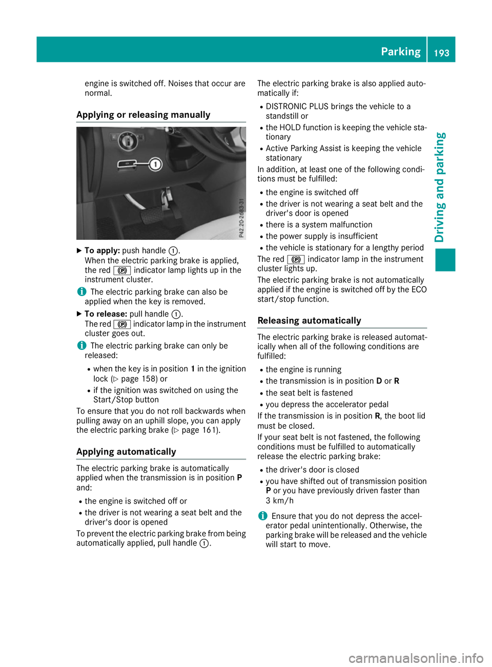
Applying or releasing manually X
To apply: push handle :.
When the electric parking brake is applied,
the red !indicator lamp lights up in the
instrument cluster.
i The electric parking brake can also be
applied when the key is removed.
X To release: pull handle:.
The red !indicator lamp in the instrument
cluster goes out.
i The electric parking brake can only be
released:
R when the key is in position 1in the ignition
lock (Y page 158) or
R if the ignition was switched on using the
Start/Stop button
To ensure that you do not roll backwards when
pulling away on an uphill slope, you can apply
the electric parking brake (Y page 161).
Applying automatically The electric parking brake is automatically
applied when the transmission is in position
P
and:
R the engine is switched off or
R the driver is not wearing a seat belt and the
driver's door is opened
To prevent the electric parking brake from being
automatically applied, pull handle :.The electric parking brake is also applied auto-
matically if:
R
DISTRONIC PLUS brings the vehicle to a
standstill or
R the HOLD function is keeping the vehicle sta-
tionary
R Active Parking Assist is keeping the vehicle
stationary
In addition, at least one of the following condi-
tions must be fulfilled:
R the engine is switched off
R the driver is not wearing a seat belt and the
driver's door is opened
R there is a system malfunction
R the power supply is insufficient
R the vehicle is stationary for a lengthy period
The red !indicator lamp in the instrument
cluster lights up.
The electric parking brake is not automatically
applied if the engine is switched off by the ECO
start/stop function.
Releasing automatically The electric parking brake is released automat-
ically when all of the following conditions are
fulfilled:
R
the engine is running
R the transmission is in position Dor R
R the seat belt is fastened
R you depress the accelerator pedal
If the transmission is in position R, the boot lid
must be closed.
If your seat belt is not fastened, the following
conditions must be fulfilled to automatically
release the electric parking brake:
R the driver's door is closed
R you have shifted out of transmission position
P or you have previously driven faster than
3 km/h
i Ensure that you do not depress the accel-
erator pedal unintentionally. Otherwise, the
parking brake will be released and the vehicle will start to move. Parking
193Driving and parking Z