2015 MERCEDES-BENZ GLE SUV engine
[x] Cancel search: enginePage 182 of 453
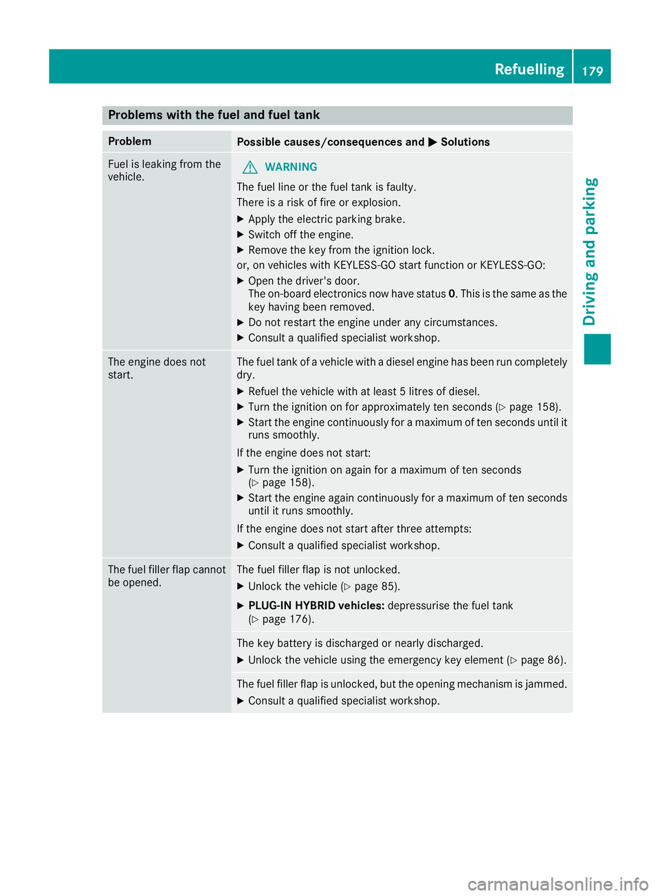
Problems with the fuel and fuel tank
Problem
Possible causes/consequences and
M
MSolutions Fuel is leaking from the
vehicle.
G
WARNING
The fuel line or the fuel tank is faulty.
There is a risk of fire or explosion. X Apply the electric parking brake.
X Switch off the engine.
X Remove the key from the ignition lock.
or, on vehicles with KEYLESS-GO start function or KEYLESS ‑GO:
X Open the driver's door.
The on-board electronics now have status 0. This is the same as the
key having been removed.
X Do not restart the engine under any circumstances.
X Consult a qualified specialist workshop. The engine does not
start. The fuel tank of a vehicle with a diesel engine has been run completely
dry.
X Refuel the vehicle with at least 5 litres of diesel.
X Turn the ignition on for approximately ten seconds (Y page 158).
X Start the engine continuously for a maximum of ten seconds until it
runs smoothly.
If the engine does not start: X Turn the ignition on again for a maximum of ten seconds
(Y page 158).
X Start the engine again continuously for a maximum of ten seconds
until it runs smoothly.
If the engine does not start after three attempts:
X Consult a qualified specialist workshop. The fuel filler flap cannot
be opened. The fuel filler flap is not unlocked.
X Unlock the vehicle (Y page 85).
X PLUG-IN HYBRID vehicles: depressurise the fuel tank
(Y page 176). The key battery is discharged or nearly discharged.
X Unlock the vehicle using the emergency key element (Y page 86).The fuel filler flap is unlocked, but the opening mechanism is jammed.
X Consult a qualified specialist workshop. Refuelling
179Driving and parking Z
Page 183 of 453
AdBlue
®
(BlueTEC vehicles only)
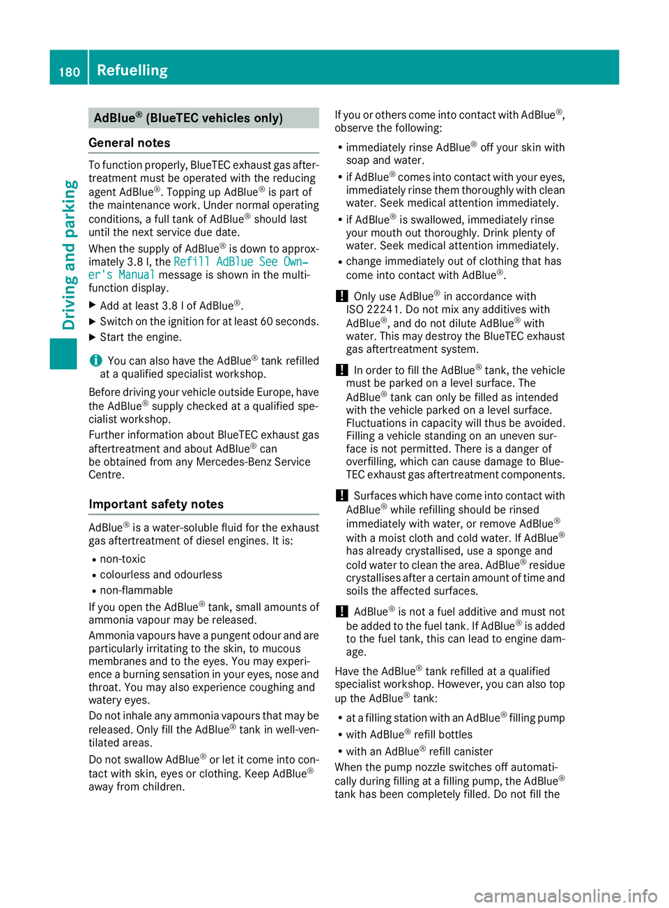
General notes To function properly, BlueTEC exhaust gas after-
treatment must be operated with the reducing
agent AdBlue ®
. Topping up AdBlue ®
is part of
the maintenance work. Under normal operating
conditions, a full tank of AdBlue ®
should last
until the next service due date.
When the supply of AdBlue ®
is down to approx-
imately 3.8 l, the Refill AdBlue See Own‐
Refill AdBlue See Own‐
er's Manual er's Manual message is shown in the multi-
function display.
X Add at least 3.8 l of AdBlue ®
.
X Switch on the ignition for at least 60 seconds.
X Start the engine.
i You can also have the AdBlue ®
tank refilled
at a qualified specialist workshop.
Before driving your vehicle outside Europe, have
the AdBlue ®
supply checked at a qualified spe-
cialist workshop.
Further information about BlueTEC exhaust gas
aftertreatment and about AdBlue ®
can
be obtained from any Mercedes-Benz Service
Centre.
Important safety notes AdBlue
®
is a water-soluble fluid for the exhaust
gas aftertreatment of diesel engines. It is:
R non-toxic
R colourless and odourless
R non-flammable
If you open the AdBlue ®
tank, small amounts of
ammonia vapour may be released.
Ammonia vapours have a pungent odour and are
particularly irritating to the skin, to mucous
membranes and to the eyes. You may experi-
ence a burning sensation in your eyes, nose and throat. You may also experience coughing and
watery eyes.
Do not inhale any ammonia vapours that may be
released. Only fill the AdBlue ®
tank in well-ven-
tilated areas.
Do not swallow AdBlue ®
or let it come into con-
tact with skin, eyes or clothing. Keep AdBlue ®
away from children. If you or others come into contact with AdBlue
®
,
observe the following:
R immediately rinse AdBlue ®
off your skin with
soap and water.
R if AdBlue ®
comes into contact with your eyes,
immediately rinse them thoroughly with clean water. Seek medical attention immediately.
R if AdBlue ®
is swallowed, immediately rinse
your mouth out thoroughly. Drink plenty of
water. Seek medical attention immediately.
R change immediately out of clothing that has
come into contact with AdBlue ®
.
! Only use AdBlue ®
in accordance with
ISO 22241. Do not mix any additives with
AdBlue ®
, and do not dilute AdBlue ®
with
water. This may destroy the BlueTEC exhaust
gas aftertreatment system.
! In order to fill the AdBlue ®
tank, the vehicle
must be parked on a level surface. The
AdBlue ®
tank can only be filled as intended
with the vehicle parked on a level surface.
Fluctuations in capacity will thus be avoided.
Filling a vehicle standing on an uneven sur-
face is not permitted. There is a danger of
overfilling, which can cause damage to Blue-
TEC exhaust gas aftertreatment components.
! Surfaces which have come into contact with
AdBlue ®
while refilling should be rinsed
immediately with water, or remove AdBlue ®
with a moist cloth and cold water. If AdBlue ®
has already crystallised, use a sponge and
cold water to clean the area. AdBlue ®
residue
crystallises after a certain amount of time and soils the affected surfaces.
! AdBlue ®
is not a fuel additive and must not
be added to the fuel tank. If AdBlue ®
is added
to the fuel tank, this can lead to engine dam-
age.
Have the AdBlue ®
tank refilled at a qualified
specialist workshop. However, you can also top
up the AdBlue ®
tank:
R at a filling station with an AdBlue ®
filling pump
R with AdBlue ®
refill bottles
R with an AdBlue ®
refill canister
When the pump nozzle switches off automati-
cally during filling at a filling pump, the AdBlue ®
tank has been completely filled. Do not fill the 180
RefuellingDriving and pa
rking
Page 187 of 453
the energy needed to operate the electric motor
and releases it again.
The electric motor uses energy that has been
stored in the high-voltage battery when pulling
away, accelerating and during the journey.
In overrun mode, kinetic energy is converted by
means of energy recuperation into electrical
energy and stored in the high-voltage battery.
Information on overrun mode (Y page 269).
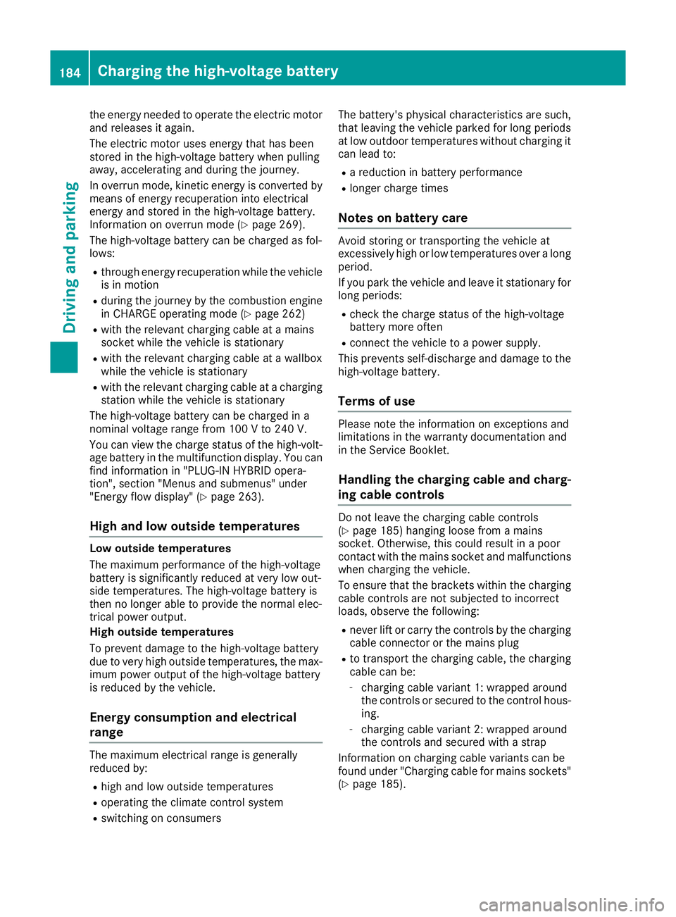
The high-voltage battery can be charged as fol-
lows:
R through energy recuperation while the vehicle
is in motion
R during the journey by the combustion engine
in CHARGE operating mode (Y page 262)
R with the relevant charging cable at a mains
socket while the vehicle is stationary
R with the relevant charging cable at a wallbox
while the vehicle is stationary
R with the relevant charging cable at a charging
station while the vehicle is stationary
The high-voltage battery can be charged in a
nominal voltage range from 100 Vto 240 V.
You can view the charge status of the high-volt-
age battery in the multifunction display. You can
find information in "PLUG-IN HYBRID opera-
tion", section "Menus and submenus" under
"Energy flow display" (Y page 263).
High and low outside temperatures Low outside temperatures
The maximum performance of the high-voltage
battery is significantly reduced at very low out-
side temperatures. The high-voltage battery is
then no longer able to provide the normal elec-
trical power output.
High outside temperatures
To prevent damage to the high-voltage battery
due to very high outside temperatures, the max- imum power output of the high-voltage battery
is reduced by the vehicle.
Energy consumption and electrical
range The maximum electrical range is generally
reduced by:
R high and low outside temperatures
R operating the climate control system
R switching on consumers The battery's physical characteristics are such,
that leaving the vehicle parked for long periods
at low outdoor temperatures without charging it
can lead to:
R a reduction in battery performance
R longer charge times
Notes on battery care Avoid storing or transporting the vehicle at
excessively high or low temperatures over a long
period.
If you park the vehicle and leave it stationary for
long periods:
R check the charge status of the high-voltage
battery more often
R connect the vehicle to a power supply.
This prevents self-discharge and damage to the
high-voltage battery.
Terms of use Please note the information on exceptions and
limitations in the warranty documentation and
in the Service Booklet.
Handling the charging cable and charg- ing cable controls Do not leave the charging cable controls
(Y
page 185) hanging loose from a mains
socket. Otherwise, this could result in a poor
contact with the mains socket and malfunctions
when charging the vehicle.
To ensure that the brackets within the charging
cable controls are not subjected to incorrect
loads, observe the following:
R never lift or carry the controls by the charging
cable connector or the mains plug
R to transport the charging cable, the charging
cable can be:
- charging cable variant 1: wrapped around
the controls or secured to the control hous-
ing.
- charging cable variant 2: wrapped around
the controls and secured with a strap
Information on charging cable variants can be
found under "Charging cable for mains sockets"
(Y page 185). 184
Charging the high-voltage batteryDriving and parking
Page 191 of 453
i
If the indicator lamps are off, lock or unlock
the vehicle. The indicator lamps will then dis- play the current status of the charging proc-
ess again.
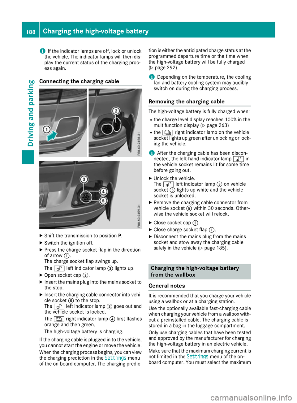
Connecting the charging cable X
Shift the transmission to position P.
X Switch the ignition off.
X Press the charge socket flap in the direction
of arrow :.
The charge socket flap swings up.
The Ì left indicator lamp =lights up.
X Open socket cap ;.
X Insert the mains plug into the mains socket to
the stop.
X Insert the charging cable connector into vehi-
cle socket Ato the stop.
The Ì left indicator lamp =goes out and
the vehicle socket is locked.
The Ý right indicator lamp ?first flashes
orange and then green.
The high-voltage battery is charging.
If the charging cable is plugged in to the vehicle,
you cannot start the engine or move the vehicle.
When the charging process begins, you can viewthe charging prediction in the Settings
Settings menu
of the on-board computer. The charging predic- tion is either the anticipated charge status at the
programmed departure time or the time when
the high-voltage battery will be fully charged
(Y page 292).
i Depending on the temperature, the cooling
fan and battery cooling system may audibly
switch on during the charging process.
Removing the charging cable The high-voltage battery is fully charged when:
R
the charge level display reaches 100% in the
multifunction display (Y page 263)
R the Ý right indicator lamp on the vehicle
socket lights up green after unlocking or lock-
ing the vehicle.
i After the charging cable has been discon-
nected, the left-hand indicator lamp Ìin
the vehicle socket remains lit for some time
before going out.
X Unlock the vehicle.
The Ì left indicator lamp =on vehicle
socket Alights up white and the vehicle
socket is unlocked.
X Remove the charging cable connector from
vehicle socket Awithin 30 seconds. Other-
wise the vehicle socket will relock.
X Close socket cap ;.
X Close charge socket flap :.
X Disconnect the mains plug from the mains
socket and stow away the charging cable
safely in the vehicle (Y page 185). Charging the high-voltage battery
from the wallbox
General notes It is recommended that you charge your vehicle
using a wallbox or at a charging station.
Use the optionally available fast-charging cable
when charging your vehicle from a wallbox with- out a preinstalled cable. The charging cable is
stored in a bag in the luggage compartment.
Only use charging cables that have been tested
and approved by the manufacturer for charging
the high-voltage battery in an electric vehicle.
Make sure that the maximum charging current is
not limited in the Settings Settingsmenu of the on-
board computer. You must select the maximum 188
Charging the high-voltage batteryDriving and parking
Page 192 of 453
value if charging at a wallbox or a charging sta-
tion (Y page 292).
Observe the "Important safety notes"
(Y page 182).
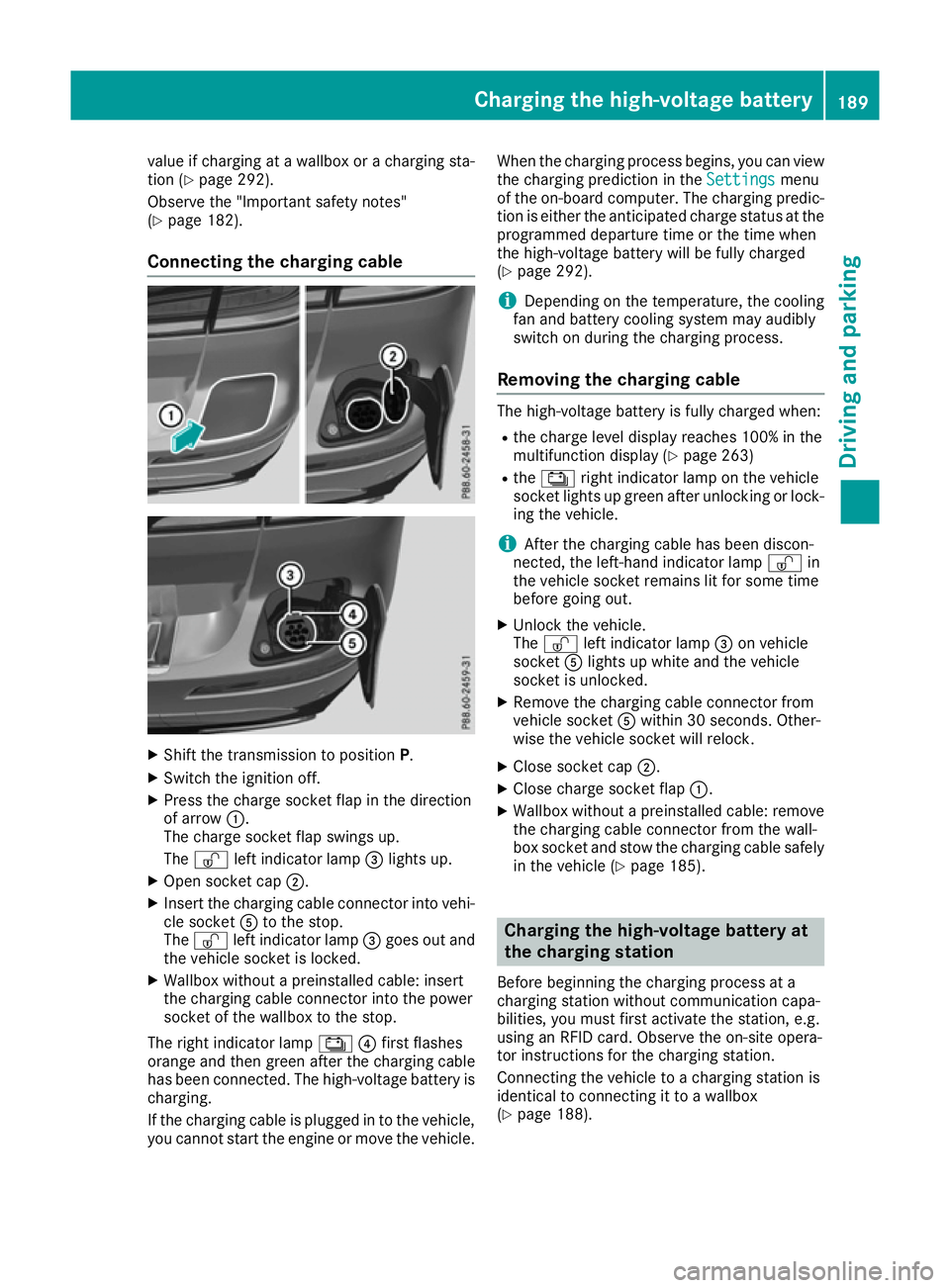
Connecting the charging cable X
Shift the transmission to position P.
X Switch the ignition off.
X Press the charge socket flap in the direction
of arrow :.
The charge socket flap swings up.
The Ì left indicator lamp =lights up.
X Open socket cap ;.
X Insert the charging cable connector into vehi-
cle socket Ato the stop.
The Ì left indicator lamp =goes out and
the vehicle socket is locked.
X Wallbox without a preinstalled cable: insert
the charging cable connector into the power
socket of the wallbox to the stop.
The right indicator lamp Ý?first flashes
orange and then green after the charging cable
has been connected. The high-voltage battery is charging.
If the charging cable is plugged in to the vehicle,
you cannot start the engine or move the vehicle. When the charging process begins, you can view
the charging prediction in the Settings
Settings menu
of the on-board computer. The charging predic-
tion is either the anticipated charge status at the
programmed departure time or the time when
the high-voltage battery will be fully charged
(Y page 292).
i Depending on the temperature, the cooling
fan and battery cooling system may audibly
switch on during the charging process.
Removing the charging cable The high-voltage battery is fully charged when:
R
the charge level display reaches 100% in the
multifunction display (Y page 263)
R the Ý right indicator lamp on the vehicle
socket lights up green after unlocking or lock-
ing the vehicle.
i After the charging cable has been discon-
nected, the left-hand indicator lamp Ìin
the vehicle socket remains lit for some time
before going out.
X Unlock the vehicle.
The Ì left indicator lamp =on vehicle
socket Alights up white and the vehicle
socket is unlocked.
X Remove the charging cable connector from
vehicle socket Awithin 30 seconds. Other-
wise the vehicle socket will relock.
X Close socket cap ;.
X Close charge socket flap :.
X Wallbox without a preinstalled cable: remove
the charging cable connector from the wall-
box socket and stow the charging cable safely in the vehicle (Y page 185). Charging the high-voltage battery at
the charging station
Before beginning the charging process at a
charging station without communication capa-
bilities, you must first activate the station, e.g.
using an RFID card. Observe the on-site opera-
tor instructions for the charging station.
Connecting the vehicle to a charging station is
identical to connecting it to a wallbox
(Y page 188). Charging the high-voltage battery
189Driving and parking Z
Page 194 of 453
Problem
Possible causes/consequences and
M
MSolutions The charging cable con-
nector cannot be
removed from the vehi-
cle socket. The charging cable connector has not been unlocked.
X Press the %button on the key.
The Ì indicator lamp on the vehicle socket lights up. The charg-
ing cable connector is unlocked.
X Remove the charging cable connector from the vehicle socket. The charging cable connector is blocked.
X Pull the charging cable close enough to the charging cable connec-
tor so that the charging cable connector is not under strain.
X Lock the vehicle and unlock it again.
X Remove the charging cable connector from the vehicle socket.
X If the charging cable connector continues to be blocked, consult a
qualified specialist workshop. Parking
Important safety notes
G
WARNING
Flammable material such as leaves, grass or
twigs may ignite if they come into contact with hot parts of the exhaust system or exhaust
gas flow. There is a risk of fire.
Park the vehicle so that no flammable mate-
rial can come into contact with hot vehicle
components. In particular, do not park on dry grassland or harvested grain fields. G
WARNING
If you leave children unattended in the vehi-
cle, they may be able to set the vehicle in
motion if, for example, they:
R release the parking brake
R shift the automatic transmission out of park
position P
R start the engine
In addition, they may operate vehicle equip-
ment and become trapped. There is a risk of
an accident and injury.
When leaving the vehicle, always take the key
with you and lock the vehicle. Never leave
children unattended in the vehicle. !
Always secure the vehicle correctly against
rolling away. Otherwise, the vehicle or its driv-
etrain could be damaged.
To ensure that the vehicle is safeguarded
against rolling away unintentionally:
R the electric parking brake must be applied.
R the transmission must be in position Pand the
key must be removed from the ignition lock
R the front wheels must be turned towards the
kerb on steep uphill or downhill gradients
R the empty vehicle must be secured at the
front axle with a wheel chock or similar
object, for example, on uphill or downhill gra-
dients
R a laden vehicle must also be secured at the
rear axle with a wheel chock or similar object,
for example, on uphill or downhill gradients Switching off the engine
Important safety notes G
WARNING
The automatic transmission switches to neu-
tral position Nwhen you switch off the engine.
The vehicle may roll away. There is a risk of an
accident.
After switching off the engine, always switch
to parking position P. Prevent the parked vehi-
cle from rolling away by applying the parking
brake. Parking
191Driving and parking Z
Page 195 of 453
Using the key
X
Apply the electric parking brake.
X Shift the transmission to position P.
X Turn the key to position 0in the ignition lock
and remove it.
The immobiliser is activated.
If you switch the engine off with the transmis-
sion in position Ror D, the automatic transmis-
sion shifts to Nautomatically.
If you then open the driver's door or the front-
passenger door or remove the key from the igni- tion, the automatic transmission shifts to P.
If you want the automatic transmission to
remain in neutral N, e.g. when having the vehicle
cleaned in an automatic car wash with a towing
system:
X Switch the ignition on.
X Depress the brake pedal and keep it
depressed.
X Shift to neutral N.
X Release the brake pedal.
X Release the electric parking brake.
X Switch off the ignition and leave the key in the
ignition lock.
Using KEYLESS-GO X
Apply the electric parking brake.
X Shift the transmission to position P.
X Press the Start/Stop button (Y page 158).
The engine stops and all the indicator lamps in the instrument cluster go out.
If you switch the engine off with the transmis-
sion in position Ror D, the automatic transmis-
sion shifts to Nautomatically.
If you then open the driver's or front-passenger door, the automatic transmission shifts to P.
If you want the automatic transmission to
remain in neutral N, e.g. when having the vehicle
cleaned in an automatic car wash with a towing
system:
X Remove the Start/Stop button from the igni-
tion lock.
X Insert the key into the ignition lock.
X Switch the ignition on.
X Depress the brake pedal and keep it
depressed.
X Shift to neutral N. X
Release the brake pedal.
X Release the electric parking brake.
X Switch off the ignition and leave the key in the
ignition lock.
i The engine can be switched off while the
vehicle is in motion by pressing and holding
the Start/Stop button for about three sec-
onds. This function operates independently of
the ECO start/stop automatic engine switch-
off function. Electric parking brake
General notes G
WARNING
If you leave children unattended in the vehi-
cle, they may be able to set the vehicle in
motion if, for example, they:
R release the parking brake
R shift the automatic transmission out of park
position P
R start the engine
In addition, they may operate vehicle equip-
ment and become trapped. There is a risk of
an accident and injury.
When leaving the vehicle, always take the key
with you and lock the vehicle. Never leave
children unattended in the vehicle.
The function of the electric parking brake is
dependent on the on-board voltage. If the on-
board voltage is low or if there is a malfunction
in the system, it may not be possible to apply the
released parking brake.
X If this is the case, only park the vehicle on
level ground and secure it to prevent it from
rolling away.
X Shift the automatic transmission to position
P.
It may not be possible to release an applied
parking brake if the on-board voltage is low or if there is a malfunction in the system. Contact a
qualified specialist workshop.
i The electric parking brake carries out a func-
tion check at regular intervals when the 192
ParkingDriving and parking
Page 196 of 453
engine is switched off. Noises that occur are
normal.
Applying or releasing manually X
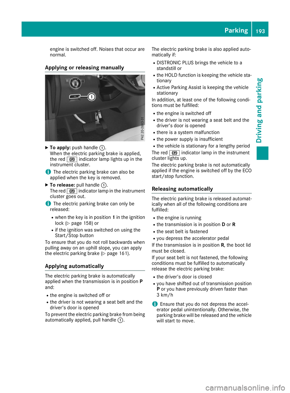
To apply: push handle :.
When the electric parking brake is applied,
the red !indicator lamp lights up in the
instrument cluster.
i The electric parking brake can also be
applied when the key is removed.
X To release: pull handle:.
The red !indicator lamp in the instrument
cluster goes out.
i The electric parking brake can only be
released:
R when the key is in position 1in the ignition
lock (Y page 158) or
R if the ignition was switched on using the
Start/Stop button
To ensure that you do not roll backwards when
pulling away on an uphill slope, you can apply
the electric parking brake (Y page 161).
Applying automatically The electric parking brake is automatically
applied when the transmission is in position
P
and:
R the engine is switched off or
R the driver is not wearing a seat belt and the
driver's door is opened
To prevent the electric parking brake from being
automatically applied, pull handle :.The electric parking brake is also applied auto-
matically if:
R
DISTRONIC PLUS brings the vehicle to a
standstill or
R the HOLD function is keeping the vehicle sta-
tionary
R Active Parking Assist is keeping the vehicle
stationary
In addition, at least one of the following condi-
tions must be fulfilled:
R the engine is switched off
R the driver is not wearing a seat belt and the
driver's door is opened
R there is a system malfunction
R the power supply is insufficient
R the vehicle is stationary for a lengthy period
The red !indicator lamp in the instrument
cluster lights up.
The electric parking brake is not automatically
applied if the engine is switched off by the ECO
start/stop function.
Releasing automatically The electric parking brake is released automat-
ically when all of the following conditions are
fulfilled:
R
the engine is running
R the transmission is in position Dor R
R the seat belt is fastened
R you depress the accelerator pedal
If the transmission is in position R, the boot lid
must be closed.
If your seat belt is not fastened, the following
conditions must be fulfilled to automatically
release the electric parking brake:
R the driver's door is closed
R you have shifted out of transmission position
P or you have previously driven faster than
3 km/h
i Ensure that you do not depress the accel-
erator pedal unintentionally. Otherwise, the
parking brake will be released and the vehicle will start to move. Parking
193Driving and parking Z