2015 MERCEDES-BENZ GLE COUPE load capacity
[x] Cancel search: load capacityPage 305 of 393
R
luggage nets on the right-hand side of the
luggage compartment
R folding coat hooks next to the grab handles in
the rear.
Observe the loading guidelines (Y page 299)
and the safety notes regarding stowage spaces
(Y page 299). Through-loading facility in the rear
compartment
If objects or loads are not secured when being
transported in the through-loading facility, they
could slip or be thrown around and thereby hit
vehicle occupants.
Observe the loading guidelines (Y page 299)
and the safety notes regarding stowage spaces
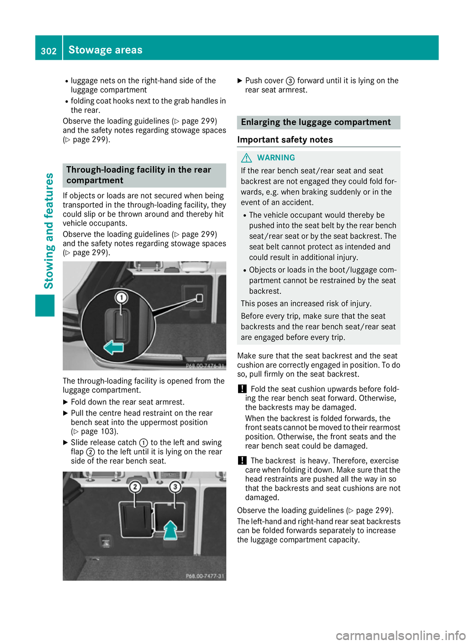
(Y page 299). The through-loading facility is opened from the
luggage compartment.
X Fold down the rear seat armrest.
X Pull the centre head restraint on the rear
bench seat into the uppermost position
(Y page 103).
X Slide release catch :to the left and swing
flap ;to the left until it is lying on the rear
side of the rear bench seat. X
Push cover =forward until it is lying on the
rear seat armrest. Enlarging the luggage compartment
Important safety notes G
WARNING
If the rear bench seat/rear seat and seat
backrest are not engaged they could fold for- wards, e.g. when braking suddenly or in the
event of an accident.
R The vehicle occupant would thereby be
pushed into the seat belt by the rear bench
seat/rear seat or by the seat backrest. The
seat belt cannot protect as intended and
could result in additional injury.
R Objects or loads in the boot/luggage com-
partment cannot be restrained by the seat
backrest.
This poses an increased risk of injury.
Before every trip, make sure that the seat
backrests and the rear bench seat/rear seat
are engaged before every trip.
Make sure that the seat backrest and the seat
cushion are correctly engaged in position. To do
so, pull firmly on the seat backrest.
! Fold the seat cushion upwards before fold-
ing the rear bench seat forward. Otherwise,
the backrests may be damaged.
When the backrest is folded forwards, the
front seats cannot be moved to their rearmost
position. Otherwise, the front seats and the
rear bench seat could be damaged.
! The backrest is heavy. Therefore, exercise
care when folding it down. Make sure that the
head restraints are pushed all the way in so
that the backrests and seat cushions are not
damaged.
Observe the loading guidelines (Y page 299).
The left-hand and right-hand rear seat backrests can be folded forwards separately to increase
the luggage compartment capacity. 302
Stowage areasStowing and features
Page 309 of 393
roof load, the handling as well as steering and
braking characteristics are severely affected.
There is a risk of an accident.
Always observe the maximum roof load and
adapt your driving style.
! Mercedes-Benz recommends that you only
use roof carriers that have been tested and
approved for Mercedes-Benz vehicles. This
helps to prevent damage to the vehicle.
Position the load on the roof carrier in such a way that the vehicle will not sustain damage
even when it is in motion.
Depending on the vehicle equipment, ensure
that when the roof carrier is fitted you can:
R raise the sliding sunroof fully
R open the panorama sliding sunroof fully
R open the tailgate fully
You will find information on the maximum roof
load in the "Technical data" section
(Y page 381).
An incorrectly secured roof carrier or roof load
may become detached from the vehicle. You
must therefore ensure that you observe the roof
carrier manufacturer's installation instructions.
Attaching the roof carrier X
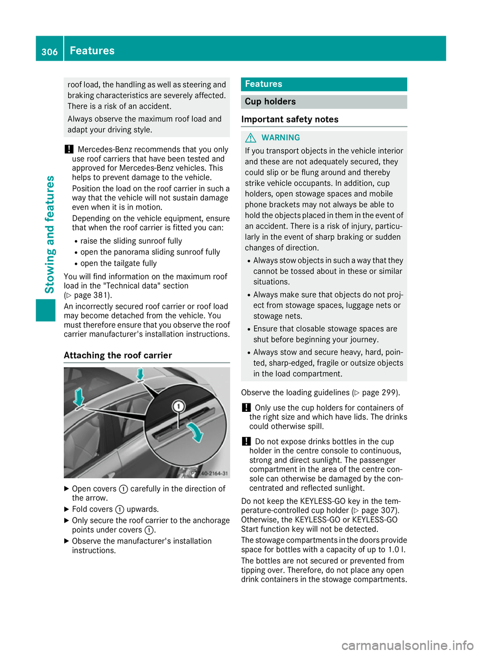
Open covers :carefully in the direction of
the arrow.
X Fold covers :upwards.
X Only secure the roof carrier to the anchorage
points under covers :.
X Observe the manufacturer's installation
instructions. Features
Cup holders
Important safety notes G
WARNING
If you transport objects in the vehicle interior and these are not adequately secured, they
could slip or be flung around and thereby
strike vehicle occupants. In addition, cup
holders, open stowage spaces and mobile
phone brackets may not always be able to
hold the objects placed in them in the event of an accident. There is a risk of injury, particu-
larly in the event of sharp braking or sudden
changes of direction.
R Always stow objects in such a way that they
cannot be tossed about in these or similar
situations.
R Always make sure that objects do not proj-
ect from stowage spaces, luggage nets or
stowage nets.
R Ensure that closable stowage spaces are
shut before beginning your journey.
R Always stow and secure heavy, hard, poin-
ted, sharp-edged, fragile or outsize objects
in the load compartment.
Observe the loading guidelines (Y page 299).
! Only use the cup holders for containers of
the right size and which have lids. The drinks
could otherwise spill.
! Do not expose drinks bottles in the cup
holder in the centre console to continuous,
strong and direct sunlight. The passenger
compartment in the area of the centre con-
sole can otherwise be damaged by the con-
centrated and reflected sunlight.
Do not keep the KEYLESS-GO key in the tem-
perature-controlled cup holder (Y page 307).
Otherwise, the KEYLESS-GO or KEYLESS-GO
Start function key will not be detected.
The stowage compartments in the doors provide
space for bottles with a capacity of up to 1.0 l.
The bottles are not secured or prevented from
tipping over. Therefore, do not place any open
drink containers in the stowage compartments. 306
FeaturesStowing and features
Page 335 of 393
Fire extinguisher
X
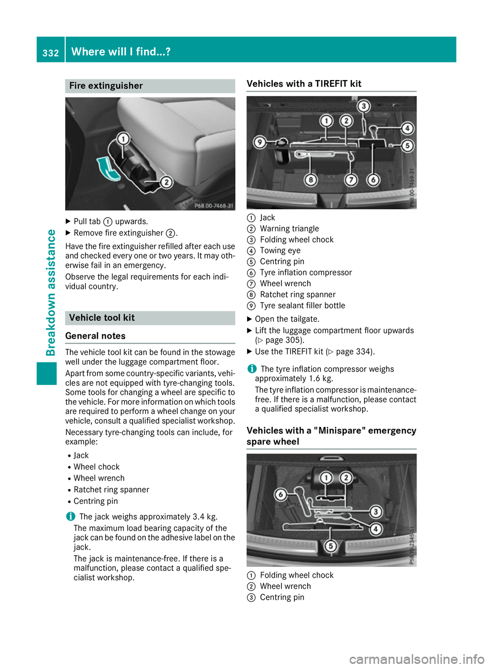
Pull tab :upwards.
X Remove fire extinguisher ;.
Have the fire extinguisher refilled after each use and checked every one or two years. It may oth-
erwise fail in an emergency.
Observe the legal requirements for each indi-
vidual country. Vehicle tool kit
General notes The vehicle tool kit can be found in the stowage
well under the luggage compartment floor.
Apart from some country-specific variants, vehi-
cles are not equipped with tyre-changing tools.
Some tools for changing a wheel are specific to the vehicle. For more information on which tools
are required to perform a wheel change on your
vehicle, consult a qualified specialist workshop.
Necessary tyre-changing tools can include, for
example:
R Jack
R Wheel chock
R Wheel wrench
R Ratchet ring spanner
R Centring pin
i The jack weighs approximately 3.4 kg.
The maximum load bearing capacity of the
jack can be found on the adhesive label on the jack.
The jack is maintenance-free. If there is a
malfunction, please contact a qualified spe-
cialist workshop. Vehicles with a TIREFIT kit
:
Jack
; Warning triangle
= Folding wheel chock
? Towing eye
A Centring pin
B Tyre inflation compressor
C Wheel wrench
D Ratchet ring spanner
E Tyre sealant filler bottle
X Open the tailgate.
X Lift the luggage compartment floor upwards
(Y page 305).
X Use the TIREFIT kit (Y page 334).
i The tyre inflation compressor weighs
approximately 1.6 kg.
The tyre inflation compressor is maintenance-
free. If there is a malfunction, please contact a qualified specialist workshop.
Vehicles with a "Minispare" emergency
spare wheel :
Folding wheel chock
; Wheel wrench
= Centring pin 332
Where will I find...?Breakdown assistance
Page 336 of 393
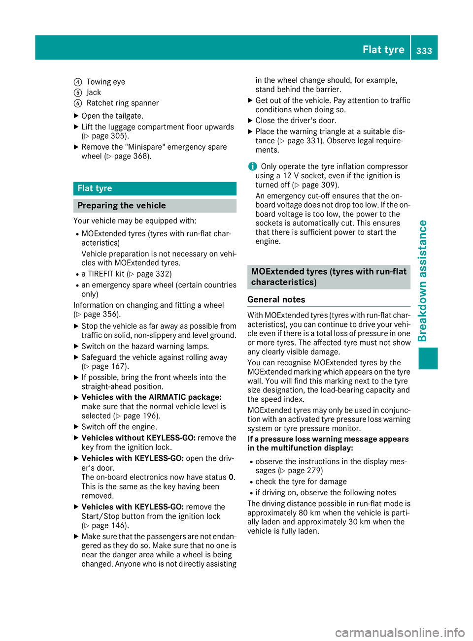
?
Towing eye
A Jack
B Ratchet ring spanner
X Open the tailgate.
X Lift the luggage compartment floor upwards
(Y page 305).
X Remove the "Minispare" emergency spare
wheel (Y page 368). Flat tyre
Preparing the vehicle
Your vehicle may be equipped with: R MOExtended tyres (tyres with run-flat char-
acteristics)
Vehicle preparation is not necessary on vehi- cles with MOExtended tyres.
R a TIREFIT kit (Y page 332)
R an emergency spare wheel (certain countries
only)
Information on changing and fitting a wheel
(Y page 356).
X Stop the vehicle as far away as possible from
traffic on solid, non-slippery and level ground.
X Switch on the hazard warning lamps.
X Safeguard the vehicle against rolling away
(Y page 167).
X If possible, bring the front wheels into the
straight-ahead position.
X Vehicles with the AIRMATIC package:
make sure that the normal vehicle level is
selected (Y page 196).
X Switch off the engine.
X Vehicles without KEYLESS-GO: remove the
key from the ignition lock.
X Vehicles with KEYLESS-GO: open the driv-
er's door.
The on-board electronics now have status 0.
This is the same as the key having been
removed.
X Vehicles with KEYLESS-GO: remove the
Start/Stop button from the ignition lock
(Y page 146).
X Make sure that the passengers are not endan-
gered as they do so. Make sure that no one is
near the danger area while a wheel is being
changed. Anyone who is not directly assisting in the wheel change should, for example,
stand behind the barrier.
X Get out of the vehicle. Pay attention to traffic
conditions when doing so.
X Close the driver's door.
X Place the warning triangle at a suitable dis-
tance (Y page 331). Observe legal require-
ments.
i Only operate the tyre inflation compressor
using a 12 V socket, even if the ignition is
turned off (Y page 309).
An emergency cut-off ensures that the on-
board voltage does not drop too low. If the on-
board voltage is too low, the power to the
sockets is automatically cut. This ensures
that there is sufficient power to start the
engine. MOExtended tyres (tyres with run-flat
characteristics)
General notes With MOExtended tyres (tyres with run-flat char-
acteristics), you can continue to drive your vehi-
cle even if there is a total loss of pressure in one or more tyres. The affected tyre must not show
any clearly visible damage.
You can recognise MOExtended tyres by the
MOExtended marking which appears on the tyre
wall. You will find this marking next to the tyre
size designation, the load-bearing capacity and
the speed index.
MOExtended tyres may only be used in conjunc- tion with an activated tyre pressure loss warning
system or tyre pressure monitor.
If a pressure loss warning message appears in the multifunction display:
R observe the instructions in the display mes-
sages (Y page 279)
R check the tyre for damage
R if driving on, observe the following notes
The driving distance possible in run-flat mode is approximately 80 km when the vehicle is parti-
ally laden and approximately 30 km when the
vehicle is fully laden. Flat tyre
333Breakdown assistance
Page 361 of 393
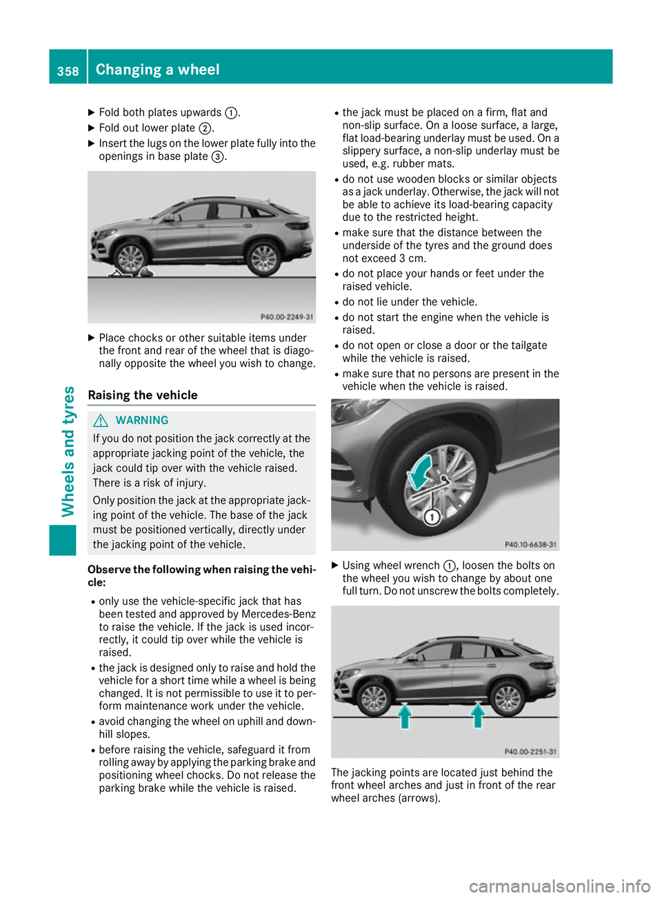
X
Fold both plates upwards :.
X Fold out lower plate ;.
X Insert the lugs on the lower plate fully into the
openings in base plate =.X
Place chocks or other suitable items under
the front and rear of the wheel that is diago-
nally opposite the wheel you wish to change.
Raising the vehicle G
WARNING
If you do not position the jack correctly at the appropriate jacking point of the vehicle, the
jack could tip over with the vehicle raised.
There is a risk of injury.
Only position the jack at the appropriate jack-
ing point of the vehicle. The base of the jack
must be positioned vertically, directly under
the jacking point of the vehicle.
Observe the following when raising the vehi- cle:
R only use the vehicle-specific jack that has
been tested and approved by Mercedes-Benz
to raise the vehicle. If the jack is used incor-
rectly, it could tip over while the vehicle is
raised.
R the jack is designed only to raise and hold the
vehicle for a short time while a wheel is being
changed. It is not permissible to use it to per- form maintenance work under the vehicle.
R avoid changing the wheel on uphill and down-
hill slopes.
R before raising the vehicle, safeguard it from
rolling away by applying the parking brake and positioning wheel chocks. Do not release theparking brake while the vehicle is raised. R
the jack must be placed on a firm, flat and
non-slip surface. On a loose surface, a large,
flat load-bearing underlay must be used. On a
slippery surface, a non-slip underlay must be
used, e.g. rubber mats.
R do not use wooden blocks or similar objects
as a jack underlay. Otherwise, the jack will not
be able to achieve its load-bearing capacity
due to the restricted height.
R make sure that the distance between the
underside of the tyres and the ground does
not exceed 3 cm.
R do not place your hands or feet under the
raised vehicle.
R do not lie under the vehicle.
R do not start the engine when the vehicle is
raised.
R do not open or close a door or the tailgate
while the vehicle is raised.
R make sure that no persons are present in the
vehicle when the vehicle is raised. X
Using wheel wrench :, loosen the bolts on
the wheel you wish to change by about one
full turn. Do not unscrew the bolts completely. The jacking points are located just behind the
front wheel arches and just in front of the rear
wheel arches (arrows).358
Changing a wheelWheels and tyres