2015 MERCEDES-BENZ GLC SUV mirror
[x] Cancel search: mirrorPage 268 of 497
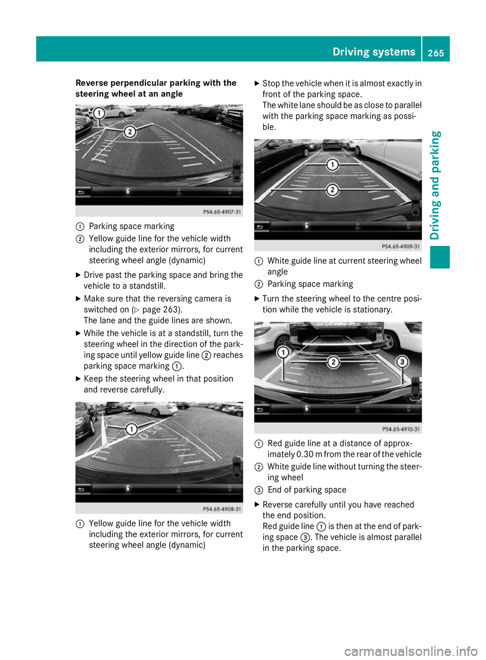
Reverse perpendicular parking with the
steering wheel at an angle :
Parking space marking
; Yellow guide line for the vehicle width
including the exterior mirrors, for current
steering wheel angle (dynamic)
X Drive past the parking space and bring the
vehicle to a standstill.
X Make sure that the reversing camera is
switched on (Y page 263).
The lane and the guide lines are shown.
X While the vehicle is at a standstill, turn the
steering wheel in the direction of the park-ing space until yellow guide line ;reaches
parking space marking :.
X Keep the steering wheel in that position
and reverse carefully. :
Yellow guide line for the vehicle width
including the exterior mirrors, for current
steering wheel angle (dynamic) X
Stop the vehicle when it is almost exactly in
front of the parking space.
The white lane should be as close to parallel
with the parking space marking as possi-
ble. :
White guide line at current steering wheel
angle
; Parking space marking
X Turn the steering wheel to the centre posi-
tion while the vehicle is stationary. :
Red guide line at a distance of approx-
imately 0.30 mfrom the rear of the vehicle
; White guide line without turning the steer-
ing wheel
= End of parking space
X Reverse carefully until you have reached
the end position.
Red guide line :is then at the end of park-
ing space =. The vehicle is almost parallel
in the parking space. Driving systems
265Driving and parking Z
Page 270 of 497
Object detection
The reversing camera helps detect moving
and stationary objects. If an object (person,
vehicle or other obstacle) is detected, this
object is marked with a bar. Objects located
some distance away from the vehicle are
marked with a yellow bar. If the distance to
the object is very small, the bar is displayed in
red.
Object detection only works in wide-angle
mode.
In order to use the function, it must be
switched on in Audio 20 or COMAND Online
(see the Digital Owner's Manual). 360° camera
General notes The 360° camera is a camera system that
consists of four cameras.
The system evaluates images from the fol-
lowing cameras:
R reversing camera
R front camera
R two side cameras in the exterior mirrors
The cameras cover the immediate surround-
ings of the vehicle. The system assists you,
e.g. when parking or at exits with reduced
visibility.
You can show pictures from the 360° camera in full-screen mode or in seven different split-
screen views on the Audio 20 or COMAND
display. A split-screen view also includes a
top view of the vehicle. This view is calculated
from the data supplied by the installed cam-
eras (virtual camera).
The seven split-screen views are:
R top view and image from the reversing cam-
era (130° viewing angle)
R top view and image from the front camera
(130° viewing angle without displaying the
maximum steering wheel angle)
R top view and enlarged rear view R
top view and enlarged front view
R top view and trailer view (vehicles with
trailer tow hitch)
R top view and images from the rear-facing
side cameras (rear wheel view)
R top view and images from the forward-
facing side cameras (front wheel view)
When the function is active and you shift the
transmission from Dor Rto N, the guide lines
in the Audio 20 or COMAND display are hid-
den.
When you change between transmission
positions Dand R, you see the previously
selected front or rear view.
Distances measured by PARKTRONIC will
also be optically displayed:
R as red or yellow brackets around the vehi-
cle symbol in top view in split-screen mode
or
R at the bottom right as red or yellow brack-
ets around the vehicle symbol in full-screen
mode
The line thickness and colour of the brackets show how far the vehicle is from an object.
R yellow brackets with thin lines:
PARKTRONIC is active
R yellow brackets with normal lines: an
object is present in close range of the vehi-
cle
R red line: an object is present in the imme-
diate close range of the vehicle
Important safety notes The 360° camera is only an aid and may show
a distorted view of obstacles, show them
incorrectly or not at all. The 360° camera is
not a substitute for attentive driving.
The responsibility for safe manoeuvring and
parking remains with you. Make sure that
there are no persons, animals or objects in
range while manoeuvring and parking.
You are always responsible for safety, and
must always pay attention to your surround-
ings when parking and manoeuvring. This Driving systems
267Driving and parking Z
Page 271 of 497
applies to the areas behind, in front of and
beside the vehicle. You could otherwise
endanger yourself and others.
The 360° camera will not function or will
function only in a limited manner:
R if the doors are open
R if the exterior mirrors are folded in
R if the boot lid or tailgate is open
R in heavy rain, snow or fog
R at night or in very dark places
R if the cameras are exposed to very bright
light
R if the area is lit by fluorescent bulbs or LED
lighting (the display may flicker)
R if the camera lenses mist up, e.g. when
driving into a heated garage in winter, caus- ing a rapid change in temperature
R if the camera lenses are dirty or covered
R if the vehicle components in which the
cameras are fitted are damaged. In this
event, have the camera position and setting
checked at a qualified specialist workshop.
Do not use the 360° camera under such cir-
cumstances. You could otherwise injure oth-
ers or damage objects when parking the vehi- cle.
The guide lines in the COMAND display show
the distances to your vehicle. The distances
only apply to road level.
In trailer mode, the guide lines are shown at
the level of the trailer tow hitch.
The camera in the rear area is protected by
means of a flap. This flap opens when the
360° camera is activated. Observe the notes on cleaning (Y page 425). For technical rea-
sons, the flap may remain open briefly after
the 360° camera has been deactivated.
On vehicles with height-adjustable suspen-
sion, due to the technical conditions, leaving
the standard height can result in:
R inaccuracies in the guide lines
R inaccuracies in the display of generated
images (top view) Activation conditions The 360° camera image can be displayed if:
R Audio 20 or COMAND Online is switched on
(see the Digital Owner's Manual)
R the 360° camera 360° camera function is switched on
i If you are driving faster than at a moderate
speed and switch on the 360° camera, a
warning message appears.
The warning message disappears if:
R you are again driving at a moderate
speed. The 360° camera is then activa-
ted.
R the message is confirmed with the %
button.
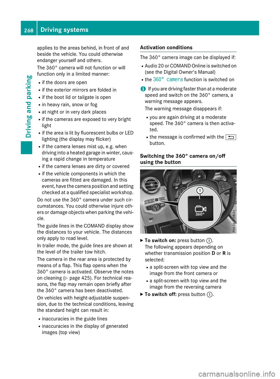
Switching the 360° camera on/off
using the button X
To switch on: press button:.
The following appears depending on
whether transmission position Dor Ris
selected:
R a split-screen with top view and the
image from the front camera or
R a split-screen with top view and the
image from the reversing camera
X To switch off: press button:.268
Driving systemsDriving and parking
Page 272 of 497
Switching on the 360° camera using
Audio 20 or COMAND Online X
To select 360° camera
360° camera in the vehicle car-
ousel: turn and press the controller.
The following appears depending on
whether transmission position Dor Ris
selected:
R a split-screen with top view and the
image from the front camera or
R a split-screen with top view and the
image from the reversing camera
Activating the 360° camera using
reverse gear You can show images from the 360° camera
automatically by engaging reverse gear.
X Make sure that the key is in position 2in the
ignition lock.
X Make sure that the Activation by R Activation by R
gear
gear function is selected in Audio 20 or
COMAND Online (see the Digital Owner's
Manual).
X To show the 360° camera image: engage
reverse gear.
The area behind the vehicle is shown in the
Audio 20 or COMAND display in split-
screen mode. You see the top view of the
vehicle and the image from the reversing
camera.
Selecting the split-screen view or full
screen mode Switching between split screen views:
X To switch to the line with the vehicle icons:
slide 5the controller.
X To select a vehicle icon: turn the controller.
Switching to full screen mode:
X 180° view
180° view Turn and press the controller. i
The full screen option is only available in
the following views:
R Top view with image from the reversing
camera
R Top view with image from the front cam-
era
Displays in the Audio 20 or COMAND
display Important safety notes
The camera system may show a distorted
view of obstacles or show them incorrectly or
not at all. Obstacles are not shown by the
system in the following locations:
R under the front and rear bumpers
R very close to the front and rear bumpers
R in the area immediately above the boot lid
handle or tailgate handle
R very close to the exterior mirrors
R in the transitional areas between the vari-
ous cameras in the virtual top view
! Objects not at ground level may appear to
be further away than they actually are, e.g.:
R the bumper of a parked vehicle
R the drawbar of a trailer
R the ball coupling of a trailer tow hitch
R the rear section of an HGV
R a slanted post
Use the guidelines only for orientation.
Approach objects no further than the bot-
tom-most guideline. Driving systems
269Driving and parking Z
Page 273 of 497
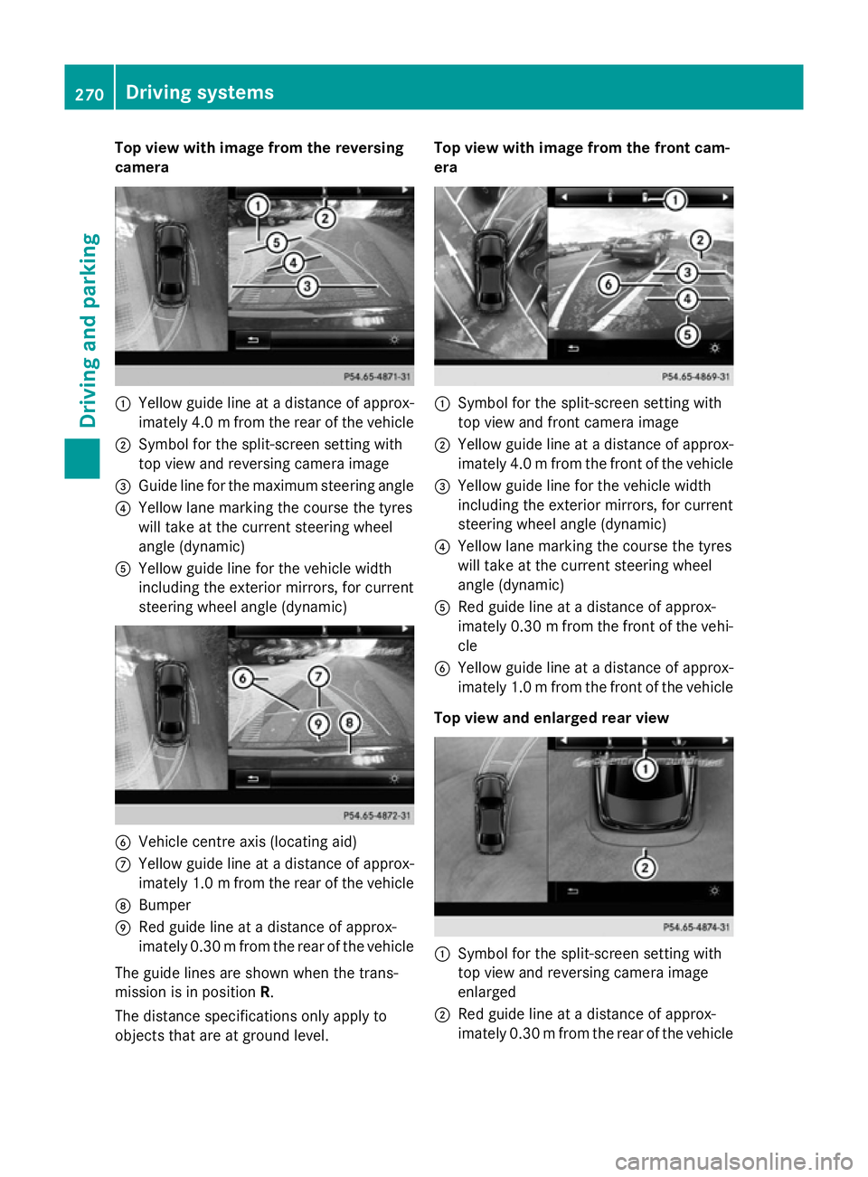
Top view with image from the reversing
camera :
Yellow guide line at a distance of approx-
imately 4.0 mfrom the rear of the vehicle
; Symbol for the split-screen setting with
top view and reversing camera image
= Guide line for the maximum steering angle
? Yellow lane marking the course the tyres
will take at the current steering wheel
angle (dynamic)
A Yellow guide line for the vehicle width
including the exterior mirrors, for current
steering wheel angle (dynamic) B
Vehicle centre axis (locating aid)
C Yellow guide line at a distance of approx-
imately 1.0 mfrom the rear of the vehicle
D Bumper
E Red guide line at a distance of approx-
imately 0.30 mfrom the rear of the vehicle
The guide lines are shown when the trans-
mission is in position R.
The distance specifications only apply to
objects that are at ground level. Top view with image from the front cam-
era
:
Symbol for the split-screen setting with
top view and front camera image
; Yellow guide line at a distance of approx-
imately 4.0 mfrom the front of the vehicle
= Yellow guide line for the vehicle width
including the exterior mirrors, for current
steering wheel angle (dynamic)
? Yellow lane marking the course the tyres
will take at the current steering wheel
angle (dynamic)
A Red guide line at a distance of approx-
imately 0.30 mfrom the front of the vehi-
cle
B Yellow guide line at a distance of approx-
imately 1.0 mfrom the front of the vehicle
Top view and enlarged rear view :
Symbol for the split-screen setting with
top view and reversing camera image
enlarged
; Red guide line at a distance of approx-
imately 0.30 mfrom the rear of the vehicle 270
Driving systemsDriving and parking
Page 274 of 497
This view assists you in estimating the dis-
tance to the vehicle behind you.
i This setting can also be selected as an
enlarged front view.
Top view with image from the side cam-
eras :
Symbol for the top view and forward-
facing side camera setting
; Yellow guide line for the vehicle width
including the exterior mirror (right side of vehicle)
= Yellow guide line for the vehicle width
including the exterior mirror (left side of
vehicle)
i You can also select the side camera set-
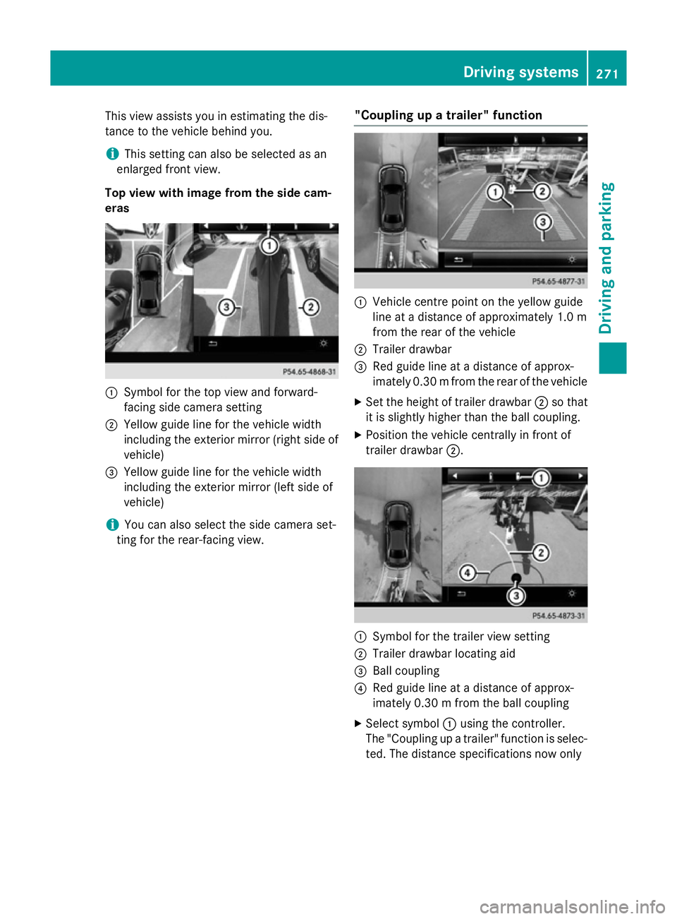
ting for the rear-facing view. "Coupling up a trailer" function :
Vehicle centre point on the yellow guide
line at a distance of approximately 1.0 m
from the rear of the vehicle
; Trailer drawbar
= Red guide line at a distance of approx-
imately 0.30 mfrom the rear of the vehicle
X Set the height of trailer drawbar ;so that
it is slightly higher than the ball coupling.
X Position the vehicle centrally in front of
trailer drawbar ;. :
Symbol for the trailer view setting
; Trailer drawbar locating aid
= Ball coupling
? Red guide line at a distance of approx-
imately 0.30 m from the ball coupling
X Select symbol :using the controller.
The "Coupling up a trailer" function is selec- ted. The distance specifications now only Driving systems
271Driving and parking Z
Page 279 of 497
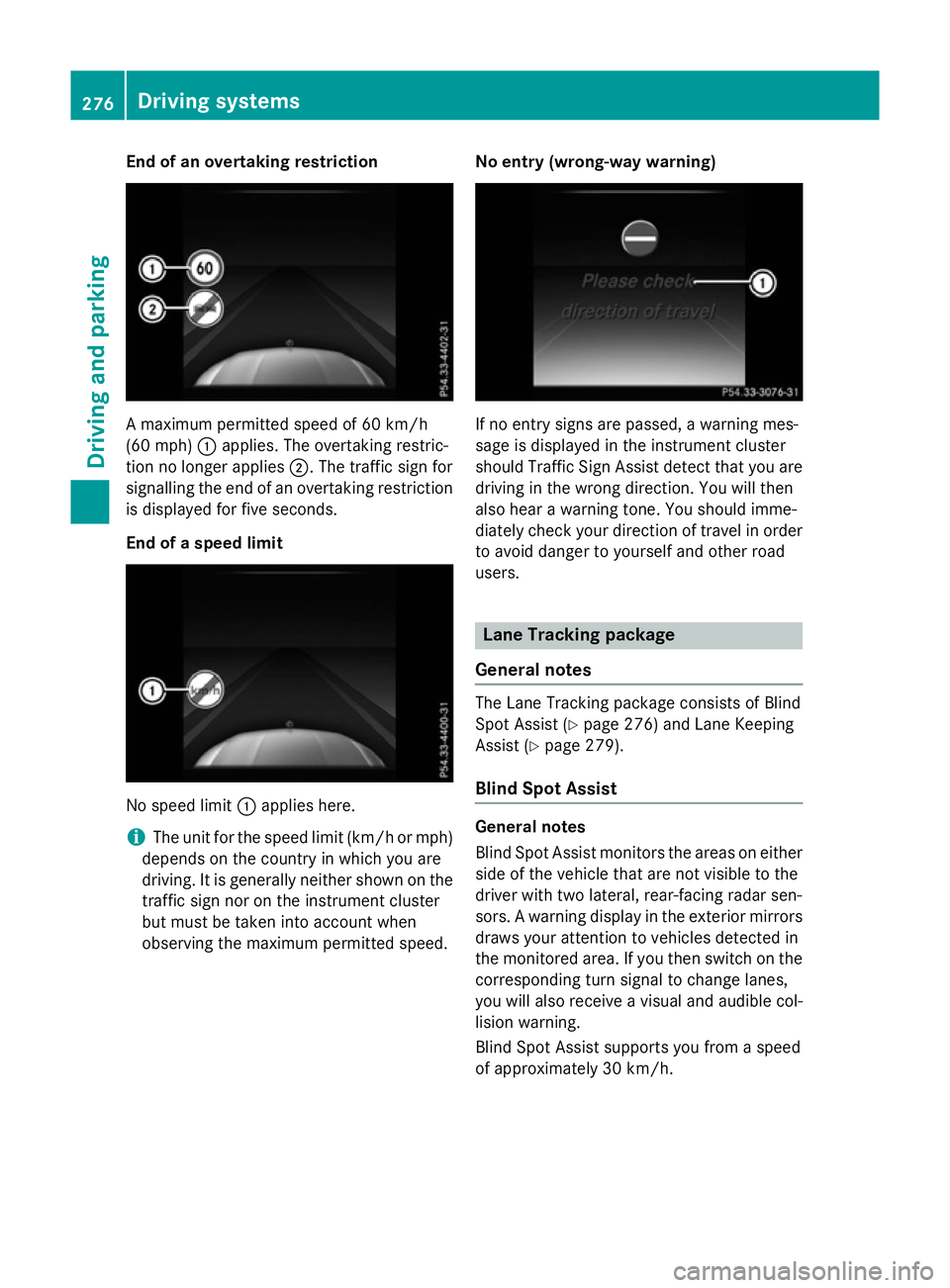
End of an overtaking restriction
A maximum permitted speed of 60 km/h
(60 mph) :applies. The overtaking restric-
tion no longer applies ;. The traffic sign for
signalling the end of an overtaking restriction
is displayed for five seconds.
End of a speed limit No speed limit
:applies here.
i The unit for the speed limit (km/h or mph)
depends on the country in which you are
driving. It is generally neither shown on the
traffic sign nor on the instrument cluster
but must be taken into account when
observing the maximum permitted speed. No entry (wrong-way warning) If no entry signs are passed, a warning mes-
sage is displayed in the instrument cluster
should Traffic Sign Assist detect that you are
driving in the wrong direction. You will then
also hear a warning tone. You should imme-
diately check your direction of travel in order to avoid danger to yourself and other road
users. Lane Tracking package
General notes The Lane Tracking package consists of Blind
Spot Assist (Y
page 276) and Lane Keeping
Assist (Y page 279).
Blind Spot Assist General notes
Blind Spot Assist monitors the areas on either
side of the vehicle that are not visible to the
driver with two lateral, rear-facing radar sen-
sors. A warning display in the exterior mirrors draws your attention to vehicles detected in
the monitored area. If you then switch on the corresponding turn signal to change lanes,
you will also receive a visual and audible col-
lision warning.
Blind Spot Assist supports you from a speed
of approximately 30 km/h. 276
Driving systemsDriving and parking
Page 281 of 497
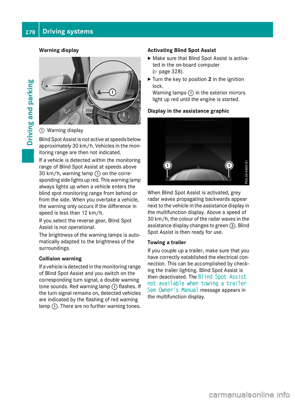
Warning display
:
Warning display
Blind Spot Assist is not active at speeds below approximately 30 km/h. Vehicles in the mon-itoring range are then not indicated.
If a vehicle is detected within the monitoring
range of Blind Spot Assist at speeds above
30 km/h, warning lamp :on the corre-
sponding side lights up red. This warning lamp
always lights up when a vehicle enters the
blind spot monitoring range from behind or
from the side. When you overtake a vehicle,
the warning only occurs if the difference in
speed is less than 12 km/h.
If you select the reverse gear, Blind Spot
Assist is not operational.
The brightness of the warning lamps is auto-
matically adapted to the brightness of the
surroundings.
Collision warning
If a vehicle is detected in the monitoring range
of Blind Spot Assist and you switch on the
corresponding turn signal, a double warning
tone sounds. Red warning lamp :flashes. If
the turn signal remains on, detected vehicles
are indicated by the flashing of red warning
lamp :. There are no further warning tones. Activating Blind Spot Assist
X Make sure that Blind Spot Assist is activa-
ted in the on-board computer
(Y page 328).
X Turn the key to position 2in the ignition
lock.
Warning lamps :in the exterior mirrors
light up red until the engine is started.
Display in the assistance graphic When Blind Spot Assist is activated, grey
radar waves propagating backwards appear
next to the vehicle in the assistance display in the multifunction display. Above a speed of
30 km/h, the colour of the radar waves in the
assistance display changes to green ;. Blind
Spot Assist is then ready for use.
Towing a trailer
If you couple up a trailer, make sure that you
have correctly established the electrical con- nection. This can be accomplished by check-ing the trailer lighting. Blind Spot Assist is
then deactivated. The Blind Spot Assist Blind Spot Assist
not
not available
available when
whentowing
towing a
atrailer
trailer
See Owner's Manual
See Owner's Manual message appears in
the multifunction display. 278
Driving systemsDriving and parking